
A1000 6-Phase/12-Pulse Input
Flange Mount and Non-Flange Mount
Installation Manual
Type: CIMR-AU4T
Models:
To properly use the product, read this manual thoroughly and retain
for easy reference, inspection, and maintenance. Ensure the end user
receives this manual.
400 V Class: 30 to 355 kW (40 to 550 HP ND)
A and CIMR-AU4T U
MANUAL NO. TOEP YAIA1U 02A

Copyright © 2015 YASKAWA AMERICA, INC. All rights reserved.
No part of this publication may be reproduced, stored in a retrieval system, or transmitted, in any form or by any means,
mechanical, electronic, photocopying, recording, or otherwise, without the prior written permission of Yaskawa. No patent
liability is assumed with respect to the use of the information contained herein. Moreover, because Yaskawa is constantly
striving to improve its high-quality products, the information contained in this manual is subject to change without notice.
Every precaution has been taken in the preparation of this manual. Yaskawa assumes no responsibility for errors or omissions.
Neither is any liability assumed for damages resulting from the use of the information contained in this publication.

Preface
1 PREFACE…………………………………………………………………………………………………..4
YASKAWA TOEP YAIA1U 02A YASKAWA AC Drive – A1000 6-Phase/12-Pulse Input Installation Manual
3
1 Preface
1 Preface
Yaskawa manufactures products used as components in a wide variety of industrial systems and equipment. The selection and
application of Yaskawa products remain the responsibility of the equipment manufacturer or end user. Yaskawa accepts no
responsibility for the way its products are incorporated into the final system design. Under no circumstances should any
Yaskawa product be incorporated into any product or design as the exclusive or sole safety control. Without exception, all
controls should be designed to detect faults dynamically and fail safely under all circumstances. All systems or equipment
designed to incorporate a product manufactured by Yaskawa must be supplied to the end user with appropriate warnings and
instructions as to the safe use and operation of that part. Any warnings provided by Yaskawa must be promptly provided to
the end user. Yaskawa offers an express warranty only as to the quality of its products in conforming to standards and
specifications published in the Yaskawa manual. NO OTHER WARRANTY, EXPRESS OR IMPLIED, IS OFFERED.
Yaskawa assumes no liability for any personal injury, property damage, losses, or claims arising from misapplication of its
products.
This manual is designed to ensure correct and suitable application of A1000-Series Drives with 6-Phase/12-Pulse rectification.
Read this manual before attempting to install or operate a drive and keep it in a safe, convenient location for future reference.
Be sure you understand all precautions and safety information before attempting application.
Use this manual as the primary reference to install and wire A1000 drives with 6-Phase/12-Pulse rectification together with
the A1000 Quick Start Guide and Technical Manual.
u
Product Overview
The A1000 6-Phase/12-Pulse drive design matches an isolation transformer with a tuned input reactor to provide a phase shift
that reduces harmonic distortion for cleaner power.
u
Applicable Documentation
The following manuals are available for A1000 series drives:
A1000 Series AC Drive 6-Phase/12-Pulse Input Installation Manual (TOEPYAIA1U02)
This guide is packaged together with the product and contains information required to install and wire the
drive with 6-Phase/12-Pulse rectification. This manual is available for download on our documentation
website, www.yaskawa.com.
A1000 Series AC Drive Quick Start Guide (TOEPC71061641)
This guide contains basic information required to install and wire the 3-Phase/6-Pulse drive and gives an
overview of fault diagnostics, maintenance, and parameter settings for 3-Phase/6-Pulse and 6-Phase/12Pulse drives. The purpose of this guide is to prepare the drive for a trial run with an application and for
basic operation. This manual is available for download on our documentation website,
www.yaskawa.com.
A1000 Series AC Drive Technical Manual (SIEPC71061641)
This manual provides detailed information on 3-Phase/6-Pulse and 6-Phase/12-Pulse parameter settings,
drive functions, and MEMOBUS/Modbus specifications. Use this manual to expand drive functionality
and to take advantage of higher performance features. This manual is available for download on our
documentation website, www.yaskawa.com.
u
Supplemental Safety Information
General Precautions
• The diagrams in this manual may be indicated without covers or safety shields to show details. Replace the covers or shields before
operating the drive and run the drive according to the instructions described in this manual.
• Any illustrations, photographs, or examples used in this manual are provided as examples only and may not apply to all products to
which this manual is applicable.
• The products and specifications described in this manual or the content and presentation of the manual may be changed without notice
to improve the product and/or the manual.
• When ordering a new copy of the manual due to damage or loss, contact your Yaskawa representative or the nearest Yaskawa sales
office and provide the manual number shown on the front cover.
• If nameplate becomes worn or damaged, order a replacement from your Yaskawa representative or the nearest Yaskawa sales office.
WARNING
Read and understand this manual before installing, operating or servicing this drive. The drive must be installed according
to this manual and local codes.
4
YASKAWA TOEP YAIA1U 02A YASKAWA AC Drive – A1000 6-Phase/12-Pulse Input Installation Manual
1 Preface
WARNING
The following conventions are used to indicate safety messages in this manual. Failure to heed these messages could result
in serious or fatal injury or damage to the products or to related equipment and systems.
DANGER
Indicates a hazardous situation, which, if not avoided, will result in death or serious injury.
WARNING
Indicates a hazardous situation, which, if not avoided, could result in death or serious injury.
WARNING! may also be indicated by a bold key word embedded in the text followed by an italicized safety message.
CAUTION
Indicates a hazardous situation, which, if not avoided, could result in minor or moderate injury.
CAUTION! may also be indicated by a bold key word embedded in the text followed by an italicized safety message.
NOTICE
Indicates a property damage message.
NOTICE: may also be indicated by a bold key word embedded in the text followed by an italicized safety message.
u
Safety Messages
DANGER
Heed the safety messages in this manual.
Failure to comply will result in death or serious injury.
The operating company is responsible for any injuries or equipment damage resulting from failure to heed the warnings in
this manual.
Electrical Shock Hazard
Before servicing, disconnect all power to the equipment.
The capacitor for the control power supply remains charged even after the power supply is turned off. The charge indicator
LED will extinguish when the control power supply voltage is below 50 Vdc. To prevent electric shock, wait for at least the
time specified on the warning label, once all indicators are OFF, measure for unsafe voltages to confirm the drive is safe
prior to servicing.
Failure to comply will result in death or serious injury.
WARNING
Sudden Movement Hazard
System may start unexpectedly upon application of power, resulting in death or serious injury.
Clear all personnel from the drive, motor and machine area before applying power. Secure covers, couplings, shaft keys and
machine loads before applying power to the drive.
YASKAWA TOEP YAIA1U 02A YASKAWA AC Drive – A1000 6-Phase/12-Pulse Input Installation Manual
5
1 Preface
WARNING
Electrical Shock Hazard
Do not attempt to modify or alter the drive in any way not explained in this manual.
Failure to comply could result in death or serious injury.
Yaskawa is not responsible for any modification of the product made by the user. This product must not be modified.
Do not allow unqualified personnel to use equipment.
Failure to comply could result in death or serious injury.
Installation, maintenance, inspection, and service must be performed only by authorized personnel familiar with installation,
adjustment and maintenance of AC drives.
Do not remove covers or touch circuit boards while the power is on.
Failure to comply could result in death or serious injury.
Make sure the protective earthing conductor complies with technical standards and local safety regulations.
Because the leakage current exceeds 3.5 mA in models 4o0302 and larger, IEC/EN 61800-5-1 states that either the power
supply must be automatically disconnected in case of discontinuity of the protective earthing conductor or a protective
earthing conductor with a cross-section of at least 10 mm2 (Cu) or 16 mm2 (Al) must be used. Failure to comply may result
in death or serious injury.
Always use appropriate equipment for Ground Fault Circuit Interrupters (GFCIs).
The drive can cause a residual current with a DC component in the protective earthing conductor. Where a residual current
operated protective or monitoring device is used for protection in case of direct or indirect contact, always use a type B GFCI
according to IEC/EN 60755.
Fire Hazard
Do not use an improper voltage source.
Failure to comply could result in death or serious injury by fire.
Verify that the rated voltage of the drive matches the voltage of the incoming power supply before applying power.
Install adequate branch circuit protection according to applicable local codes and this Installation Manual. Failure
to comply could result in fire and damage to the drive or injury to personnel.
The device is suitable for use on a circuit capable of delivering not more than 100,000 RMS symmetrical amperes, 480 Vac
maximum (400 V class), when protected by branch circuit protection devices specified in this manual.
Crush Hazard
Do not use this drive in lifting applications without installing external safety circuitry to prevent accidental dropping
of the load.
The drive does not possess built-in load drop protection for lifting applications.
Failure to comply could result in death or serious injury from falling loads.
Install electrical and/or mechanical safety circuit mechanisms independent of drive circuitry.
CAUTION
Crush Hazard
Do not carry the drive by the front cover.
Failure to comply may result in minor or moderate injury from the main body of the drive falling.
6
YASKAWA TOEP YAIA1U 02A YASKAWA AC Drive – A1000 6-Phase/12-Pulse Input Installation Manual

1 Preface
NOTICE
Observe proper electrostatic discharge procedures (ESD) when handling the drive and circuit boards. Failure to
comply may result in ESD damage to the drive circuitry.
Do not perform a withstand voltage test on any part of the drive.
Failure to comply could result in damage to the sensitive devices within the drive.
Do not operate damaged equipment.
Failure to comply could result in further damage to the equipment. Do not connect or operate any equipment with visible
damage or missing parts.
If a fuse is blown or a Ground Fault Circuit Interrupter (GFCI) is tripped, check the wiring and the selection of the
peripheral devices.
Contact your supplier if the cause cannot be identified after checking the above.
Do not restart the drive immediately operate the peripheral devices if a fuse is blown or a GFCI is tripped.
Check the wiring and the selection of peripheral devices to identify the cause. Contact your supplier before restarting the
drive or the peripheral devices if the cause cannot be identified.
Do not expose the drive to halogen group disinfectants.
Failure to comply may cause damage to the electrical components in the drive.
Do not pack the drive in wooden materials that have been fumigated or sterilized. Do not sterilize the entire package after
the product is packed.
General Application Precautions
n
Selection
Installing a Transformer
Install a 6-Phase/12-Pulse isolation transformer with each of the output windings phase shifted by 30 electrical degrees or
install a Hybrid 6-Phase topology on the power supply.
Installing a Reactor
Use an AC reactor or DC link choke in the following situations:
• to suppress harmonic current.
• to smooth peak current that results from capacitor switching.
• when the power supply is above 600 kVA.
• when the drive is running from a power supply system with thyristor converters.
4000
Power supply harmonics
reactor required
Power Supply
Capacity (kVA)
600
0
Drive Capacity (kVA)
Figure Installing a Reactor
Reactor
unnecessary
60 400
Inspection and Maintenance
WARNING! Electrical Shock Hazard. Capacitors for the control power supply do not immediately discharge after shutting off the power.
Wait for at least the amount of time specified on the drive before touching any components after shutting off the power. Failure to comply
may cause injury to personnel from electrical shock.
YASKAWA TOEP YAIA1U 02A YASKAWA AC Drive – A1000 6-Phase/12-Pulse Input Installation Manual
7
1 Preface
WARNING! Electrical Shock Hazard. When a drive is running a PM motor, voltage continues to be generated at the motor terminals after
the drive is shut off while the motor coasts to stop. Take the precautions described below to prevent shock and injury:
∙ In applications where the machine can still rotate after the drive has fully stopped a load, install a switch to the drive output side to disconnect
the motor and the drive.
∙ Do not allow an external force to rotate the motor beyond the maximum allowable speed or to rotate the motor when the drive has been
shut off.
∙ Wait for at least the time specified on the warning label after opening the load switch on the output side before inspecting the drive or
performing any maintenance.
∙ Do not open and close the load switch while the motor is running.
∙ If the motor is coasting, make sure the power to the drive is turned on and the drive output has completely stopped before closing the load
switch.
WARNING! Burn Hazard. Because the heatsink can get very hot during operation, take proper precautions to prevent burns. When replacing
the cooling fan, shut off the power and wait at least 15 minutes to be sure that the heatsink has cooled down. Failure to comply may cause
burn injury to personnel.
Wiring
All wire ends should use ring terminals for UL/cUL compliance. Use only the tools recommended by the terminal manufacturer
for crimping.
Transporting the Drive
NOTICE: Never steam clean the drive. During transport, keep the drive from coming into contact with salts, fluorine, bromine, phthalate
ester, and other such harmful chemicals.
u
Drive Label Warning Example
Always heed the warning information listed in Figure .
WARNING
Risk of electric shock.
●
Read manual before installing.
●
Wait 5 minutes for capacitor
discharge after disconnecting
power supply.
●
To conform to requirements,
make sure to ground the supply
neutral for 400V class.
●
After opening the manual switch
between the drive and motor,
please wait 5 minutes before
inspecting, performing
maintenance or wiring the drive.
Hot surfaces
●
Top and Side surfaces may
become hot. Do not touch.
Figure Warning Information Example
u
Warranty Information
Restrictions
n
The drive is not designed or manufactured for use in devices or systems that may directly affect or threaten human lives or
health.
Customers who intend to use the product described in this manual for devices or systems relating to transportation, health
care, space aviation, atomic power, electric power, or in underwater applications must first contact their Yaskawa
representatives or the nearest Yaskawa sales office.
WARNING! Injury to Personnel. This product has been manufactured under strict quality-control guidelines. However, if this product is to
be installed in any location where failure of this product could involve or result in a life-and-death situation or loss of human life or in a facility
where failure may cause a serious accident or physical injury, safety devices must be installed to minimize the likelihood of any accident.
8
YASKAWA TOEP YAIA1U 02A YASKAWA AC Drive – A1000 6-Phase/12-Pulse Input Installation Manual

Installation Manual
1 RECEIVING………………………………………………………………………………………………10
2 MECHANICAL INSTALLATION…………………………………………………………………..13
3 ELECTRICAL INSTALLATION……………………………………………………………………15
4 START-UP PROGRAMMING & OPERATION……………………………………………….26
5 TROUBLESHOOTING………………………………………………………………………………..27
6 DRIVE OPTIONS AND PERIPHERAL DEVICES…………………………………………..29
7 PERIODIC INSPECTION & MAINTENANCE…………………………………………………35
8 SPECIFICATIONS……………………………………………………………………………………..38
9 PARAMETER TABLE………………………………………………………………………………..77
10 STANDARDS COMPLIANCE……………………………………………………………………..81
YASKAWA TOEP YAIA1U 02A YASKAWA AC Drive – A1000 6-Phase/12-Pulse Input Installation Manual
9
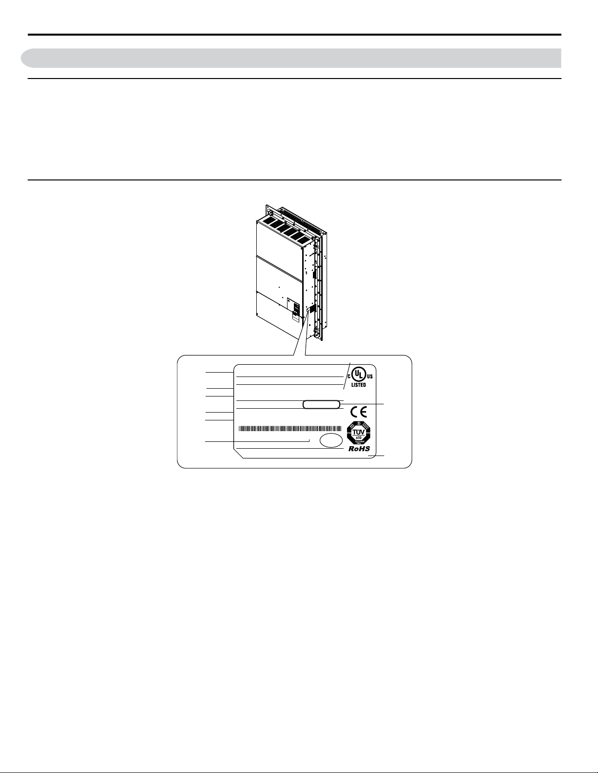
PRG : 1010
IND.CONT.EQ.
7J48
CIMR-AU4T0675UAA REV:A
:
:
AC6PH(12P) 380-480V 50/60Hz 603A/511A
: AC3PH 0-480V 0-400Hz 675A/605A
: 220kg
:
:
: E131457 IP00
PASS
MODEL
INPUT
OUTPUT
MASS
O / N
S / N
FILE NO
I
H
G
F
E
D
B
C
A
C/C CIMR-AU4T0675UAA
YASKAWA ELECTRIC CORPORATION
2-1 Kurosaki-shiroishi, Yahatanishi-ku, Kitakyushu 806-0004 Japan
MADE IN JAPAN
1 Receiving
1 Receiving
u
Model Number and Nameplate Check
Please perform the following tasks after receiving the drive:
• Inspect the drive for damage.
If the drive appears damaged upon receipt, contact the shipper immediately.
• Verify receipt of the correct model by checking the information on the nameplate.
• If you have received the wrong model or the drive does not function properly, contact your supplier.
u
Nameplate
A – Normal Duty / Heavy Duty Amps
B – Software version
C –
Address
<1>
D – Enclosure type
F – Lot number
G – Output specifications
H – Input specifications
I – AC drive model
E – Serial number
Figure 1 Nameplate Information Example
<1> The address of the head office of Yaskawa Electric Corporation (responsible for product liability) is shown on the nameplate.
10
YASKAWA TOEP YAIA1U 02A YASKAWA AC Drive – A1000 6-Phase/12-Pulse Input Installation Manual

CIMR
—
A U 4 T
0675 U
A A
Drive
A1000
Series
Letter
Enclosure
Type
Design
Revision
Order
Letter
Region
Code
USA
No. Voltage Class
Letter
Environmental
Specification
A Standard
380-480 Vac 4
Customized
Specification
6-Phase/
12-Pulse Input
<2>
A
Refer to the tables below
Flange Type
U
<1>
U
Open Type
(Non-Flange)
1 Receiving
<1> Provides method of mounting drive with backside (heatsink) external to enclosure with NEMA 12 integrity.
<2> Drives with these specifications do not guarantee complete protection for the environmental conditions indicated.
6-Phase/12-Pulse 400 V Class Rated Output
n
Table 1 Model Number and Specifications (400 V Class)
Drive Model
4T0058o
4T0072o
4T0088o
4T0103o
4T0139o
4T0165o
4T0208o
4T0250o
4T0296o
4T0362o
4T0414o
4T0515o
4T0675o
Normal Duty (ND)
C6-01 = 1
Max. Motor Capacity
kW (HP)
30 (40) 58
37 (50) 72
45 (60) 88
55 (75) 103
75 (100) 139
90 (125) 165
110 (150) 208
132 (200) 250
160 (250) 296
185 (300) 362
220 (350) 414
250 (400-450) 515
355 (500-550) 675
Rated Output
Current A
Drive Model
4T0058o
4T0072o
4T0088o
4T0103o
4T0139o
4T0165o
4T0208o
4T0250o
4T0296o
4T0362o
4T0414o
4T0515o
4T0675o
Heavy Duty (HD)
C6-01 = 0
Max. Motor Capacity
kW (HP)
22 (25-30) 45
30 (40) 60
37 (50-60) 75
45 (50-60) 91
55 (75) 112
75 (100) 150
90 (125-150) 180
110 (150) 216
132 (200) 260
160 (250) 304
185 (300) 370
220 (350) 450
315
(400-450-500)
Rated Output
Current A
605
YASKAWA TOEP YAIA1U 02A YASKAWA AC Drive – A1000 6-Phase/12-Pulse Input Installation Manual
11
1 Receiving
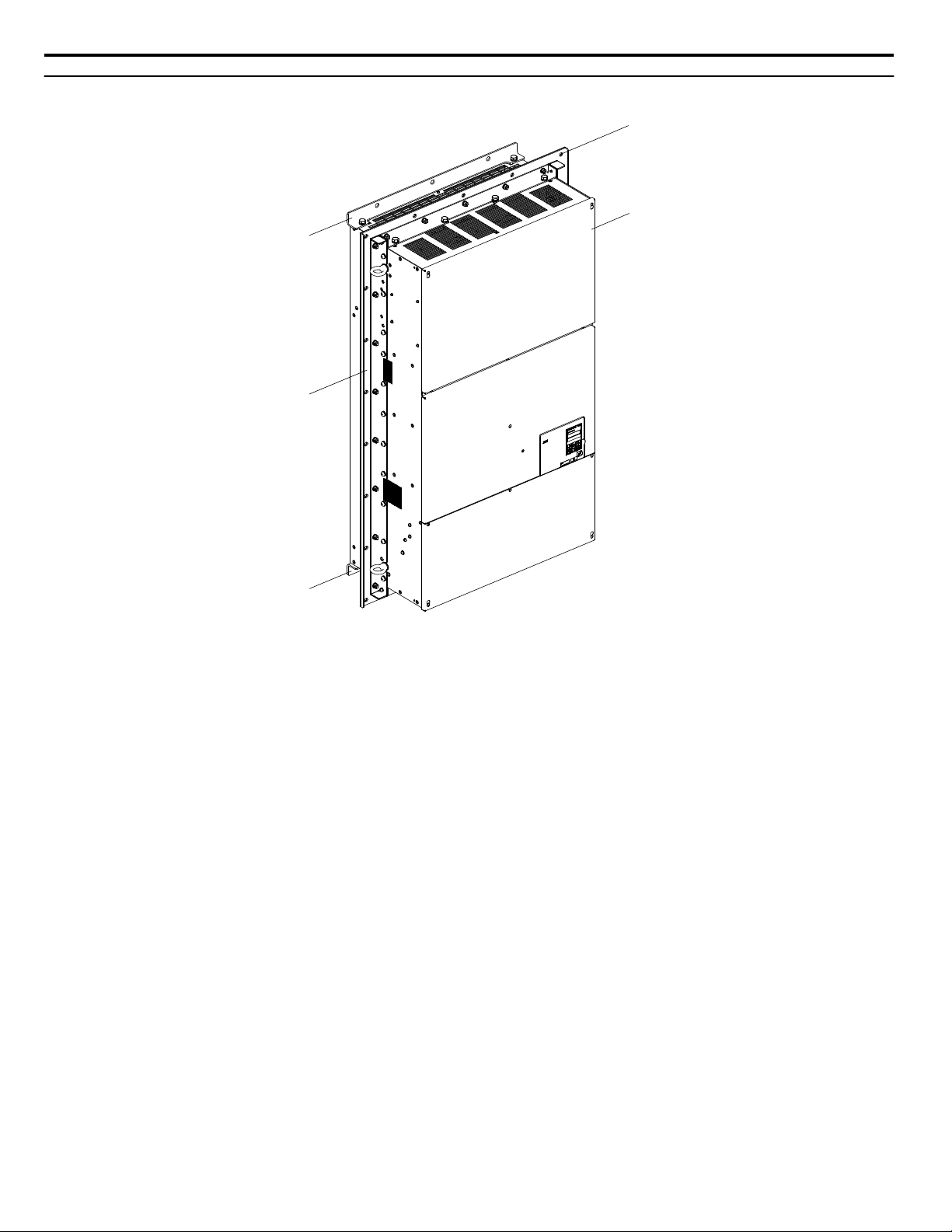
u
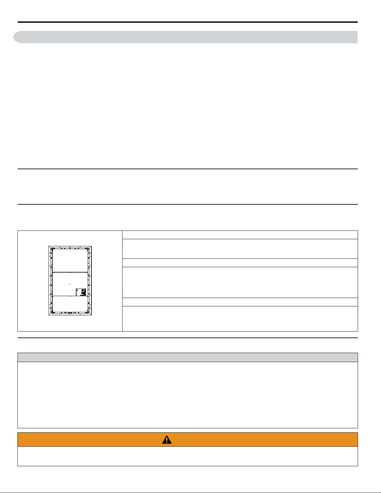
6-Phase/12-Pulse Component Names
A – Installation hole
B – 6-Phase/12-Pulse Drive
Figure 2 Flange Type Enclosure Example (Models 4TooooU)
<1> Provides method of mounting drive with backside (heatsink) external to enclosure with NEMA 12 integrity. 4TooooU models
only.
NOTICE: Remove the shipping package attachments before installing. The shipping package attachments will interfere with the cutting of
the panel when installing the drive.
C –
Mounting flange
D – Shipping package attachment (to
be removed before installation)
<1>
12
YASKAWA TOEP YAIA1U 02A YASKAWA AC Drive – A1000 6-Phase/12-Pulse Input Installation Manual

2 Mechanical Installation
2 Mechanical Installation
This section outlines specifications, procedures, and the environment for proper mechanical installation of the drive.
u
Installation Environment
Install the drive in an environment matching the specifications in Table 2 to help prolong the optimum performance life of
the drive.
Table 2 Installation Environment
Environment Conditions
Installation Area Indoors
Flange Type Enclosure: -10 °C to +40 °C (14 °F to 104 °F)
Non-Flange Type Enclosure: -10 °C to +50 °C (14 °F to 122 °F)
Ambient Temperature
Humidity 95% RH or less and free of condensation
Storage Temperature -20 °C to +60 °C
Surrounding Area
Altitude Up to 1000 m without derating, up to 3000 m with output current and voltage derating.
Vibration
Orientation Install the drive vertically to maintain maximum cooling effects.
Drive reliability improves in environments without wide temperature fluctuations.
When using the drive in an enclosure panel, install a cooling fan or air conditioner in the area to ensure that the air
temperature inside the enclosure does not exceed the specified levels.
Do not allow ice to develop on the drive.
Install the drive in an area free from:
• oil mist and dust
• metal shavings, oil, water, or other foreign materials
• radioactive materials
• combustible materials (e.g., wood)
• harmful gases and liquids
• excessive vibration
• chlorides
• direct sunlight.
10 Hz to 20 Hz at 9.8 m/s
20 Hz to 55 Hz at 5.9 m/s2 (Models 4T0058o to 4T0165o) or 2.0 m/s2 (Models 4T0208o to 4T0675o)
2
NOTICE: Avoid placing drive peripheral devices, transformers, or other electronics near the drive as the noise created can lead to erroneous
operation. If such devices must be used in close proximity to the drive, take proper steps to shield the drive from noise.
NOTICE: Damage to Equipment. Drive heatsink air outlet temperature may be over 80 °C. Do not install components above the air outlet
that may be damaged by 80 °C air temperature.
NOTICE: Damage to Equipment. Prevent foreign matter such as metal shavings and wire clippings from falling into the drive during
installation. Failure to comply could result in damage to the drive. Place a temporary cover over the top of the drive during installation.
Remove the temporary cover before drive start-up, as the cover will reduce ventilation and cause the drive to overheat.
YASKAWA TOEP YAIA1U 02A YASKAWA AC Drive – A1000 6-Phase/12-Pulse Input Installation Manual
13
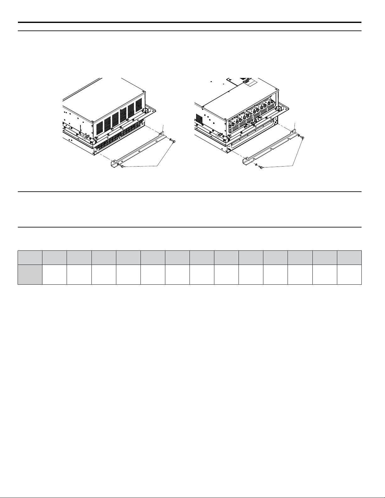
Screws
Shipping Package
Attachment
Shipping Package
Attachment
Top Side
Screws
Bottom Side
2 Mechanical Installation
u
Removing the Shipping Package Attachments
Remove the shipping package attachments before installation.
Note: The number of screws varies in accordance with the drive model.
Figure 3 Removing the Shipping Package Attachments
u
Exterior and Mounting Dimensions
Refer to External Mounting and Panel Cutout Dimensions on page 44 for 6-phase/12-pulse exterior and mounting
dimensions.
u
Weights
Table 3 Drive Weights
Drive
Model
Drive
Weight
kg (lb)
4T0058o 4T0072o 4T0088o 4T0103o 4T0139o 4T0165o 4T0208o 4T0250o 4T0296o 4T0362o 4T0414o 4T0515o 4T0675o
21 (46.2) 24 (52.8) 35 (77.0) 35 (77.0) 39 (85.8) 40 (88.2) 78 (172) 90 (198) 95 (209) 97 (214) 127 (280) 210 (463) 215 (474)
14
YASKAWA TOEP YAIA1U 02A YASKAWA AC Drive – A1000 6-Phase/12-Pulse Input Installation Manual

3 Electrical Installation
3 Electrical Installation
u
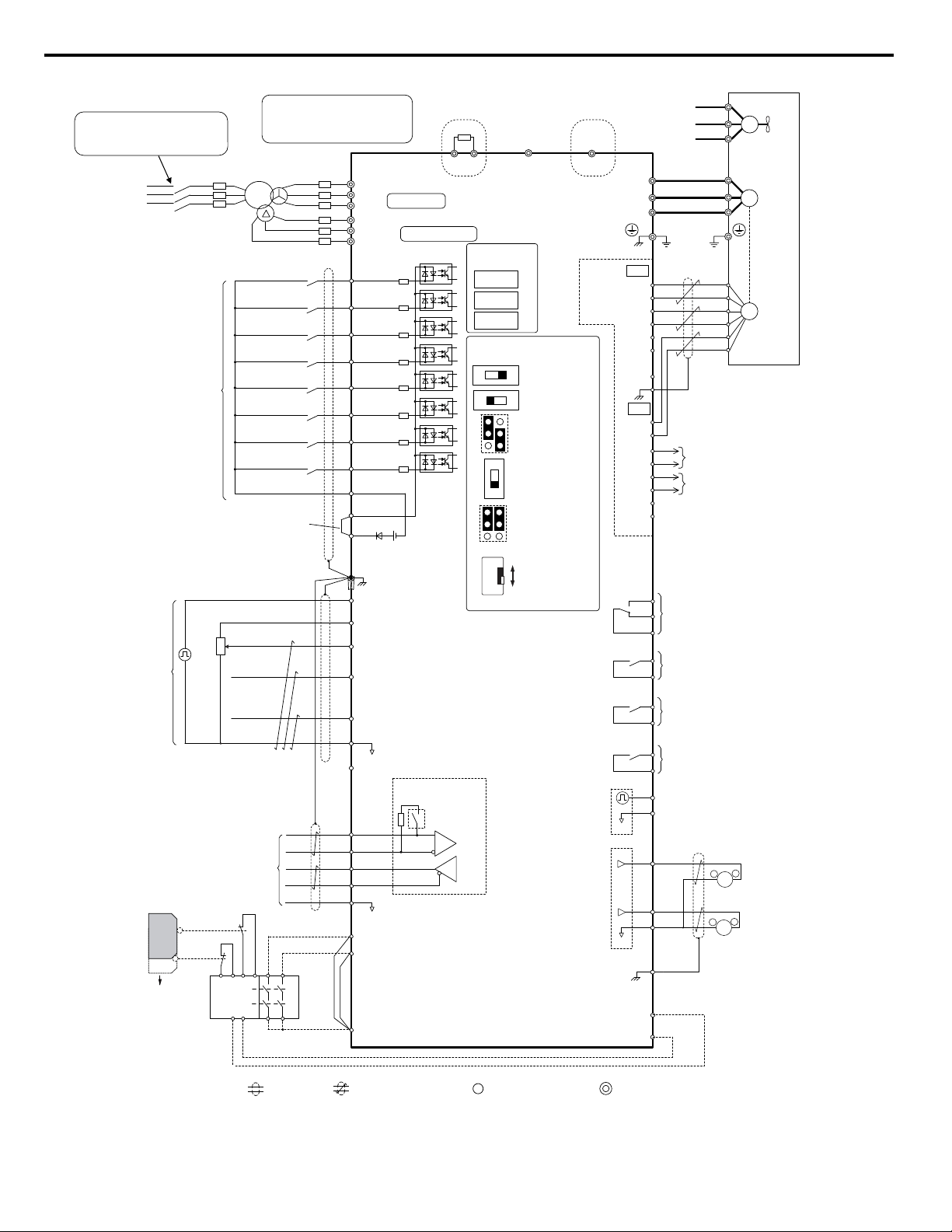
Standard Connection Diagram
Connect the drive and peripheral devices as shown in Figure 4. It is possible to set and run the drive via the digital operator
without connecting digital I/O wiring.
WARNING! Fire Hazard — Drive Short-Circuit Current Rating. Install adequate branch circuit protection according to applicable local codes
and this manual. Failure to comply could result in fire and damage to the drive or injury to personnel. The device is suitable for use on a
circuit capable of delivering not more than 100,000 RMS symmetrical amperes, 480 Vac maximum (400 V class), when protected by branch
circuit protection devices specified in this manual.
NOTICE: Route motor leads U/T1, V/T2, and W/T3 separate from all other leads to reduce possible interference related issues. Failure to
comply may result in abnormal operation of drive and nearby equipment.
NOTICE: Equipment Hazard. Standard motors used with PWM drives may experience winding failures due to surge voltages when input
line voltage is greater than 480 V or motor wire distance is greater than 100 meters. Select a motor design with insulation tolerant of surge
voltages, such as drive-rated motor for use with PWM drives. Failure to comply could lead to motor winding failure.
Note: The minimum load for the relay outputs M1-M2, M3-M4, M5-M6, and MA-MB-MC is 10 mA.
YASKAWA TOEP YAIA1U 02A YASKAWA AC Drive – A1000 6-Phase/12-Pulse Input Installation Manual
15
+
-
+
—
+
+
-
+
—
+
+
-
S1
S2
S3
S4
S5
S6
S7
MP
DM
DM
RP
A1
A2
A3
0 V
AC
R
R
S
S-
IG
H1
H2
HC
Drive
2 k
S8
SC
0 V
0 V
AC
FM
AM
AC
E (G)
S1
S2
<11>
<6>
<12>
<13>
<8>
<10>
<6>
<4>
<3>
+24 V
+V
MA
M1
M2
MB
MC
Forward Run / Stop
Reverse Run / Stop
External fault
Fault reset
Multi-speed step 1
Multi-speed step 2
External Baseblock
Jog speed
Multi-function
digtial inputs
(default setting)
Sink / Source mode
selection wire link
(default: Sink)
CN5-C
CN5-B
CN5-A
Option board
Pulse Train Input
(max 32 kHz)
Shield ground
terminal
Multi-function
analog/pulse
train inputs
Power supply +10.5 Vdc, max. 20 mA
Analog Input 1 (Frequency Reference Bias)
-10 to +10 Vdc (20 k )
Analog Input 2 (Frequency Reference Bias)
-10 to +10 Vdc (20 k )
0 or 4 to 20 mA (250 )
Analog Input 3 / PTC Input (Aux. frequency
reference)
-10 to +10 Vdc (20 k )
—V
Power supply, -10.5 Vdc, max. 20 mA
Safety
switch
MEMOBUS/Modbus comm.
RS-422/RS-485
max. 115.2 kBps
Safe Disable inputs
Wire
jumper
Open
Safety relay /
controller
Termination resistor
(120 , 1/2 W)
DIP
Switch S2
Fault relay output
250 Vac, max. 1 A
30 Vdc, max 1 A
(min. 5 Vdc, 10 mA)
Multi-function relay output (During Run)
250 Vac, max. 1 A
30 Vdc, max 1 A
(min. 5 Vdc, 10 mA)
Multi-function pulse train output
(Output frequency)
0 to 32 kHz (2.2 k )
Multi-function analog output 1
(Output frequency)
-10 to +10 Vdc (2mA)
or 4 to 20 mA
EDM (Safety Electronic Device Monitor)
Control Circuit
shielded line
twisted-pair shielded line
main circuit terminal
control circuit terminal
M3
M4
Multi-function relay output (Zero Speed)
250 Vac, max. 1 A
30 Vdc, max 1 A
(min. 5 Vdc, 10 mA)
M5
M6
Multi-function relay output (Speed Agree 1)
250 Vac, max. 1 A
30 Vdc, max 1 A
(min. 5 Vdc, 10 mA)
SP
SN
<9>
AMFM
V
I
V
I
DIP Switch S1
A2 Volt/Curr. Sel
DIP Switch S4
A3 Analog/PTC
Input Sel
PTC
AI
Off
On
DIP Switch S2
Term. Res. On/Off
Jumper S3
H1, H2
Sink/Source Sel.
Jumper S5
AM/FM Volt./Curr.
Selection
Terminal board
jumpers and switches
FM
+
-
AM
<5>
<14>
Ω
Ω
Ω
Ω
Ω
Ω
<13>
Multi-function analog output 2
(Output current)
-10 to +10 Vdc (2mA)
or 4 to 20 mA
<15>
<6>
A+
A-
B-
Z-
B+
Z+
a+
ab+
bz+
z-
FE
IP
IG
TB1
SD
TB2
B track monitor
A track monitor
M
U/T1
V/T2
W/T
U
FU
FV
FW
V
W
3
Ground
Cooling fan
PG
M
PG- X3
connectors
(option)
Ω
Slide Switch S6
DM+, DMN.C./N.O. Selection
N.C.
N.O.
<7>
Terminals B1, B2, -, and +3, B1
are for power option connections.
Never connect power supply lines
to these terminals
B1 B2
Fuse
Main Circuit
Three-Phase
Power Supply
380 to 480 V
50/60 Hz
Wiring sequence should shut off
power to the drive when a fault
output is triggered.
BCP
R/L1
S/L2
T/L3
R1/L11
S1/L21
T1/L31
R
S
T
Main
Switch
Models 4T0058 and 4T0072
Dynamic braking resistor
(option) <1> <2>
U1
V1
W1
W2
V2
U2
—
+3
Models 4T0088 to 4T0675
CDBR dynamic braking unit
(option) <1> <2>
<16>
<17>
3 Electrical Installation
Figure 4 Drive Standard Connection Diagram
16
YASKAWA TOEP YAIA1U 02A YASKAWA AC Drive – A1000 6-Phase/12-Pulse Input Installation Manual

3 Electrical Installation
<1> Set up a thermal relay sequence to disconnect drive main power in the event of an overheat condition on the dynamic
braking option.
<2> Set L8-55 to 0 to disable the protection function of the built-in braking transistor of the drive when using an optional
regenerative converter or dynamic braking option. Leaving L8-55 enabled may cause a braking resistor fault (rF). Additionally,
disable Stall Prevention (L3-04 = 0) when using an optional regenerative converter, regenerative or braking units, or dynamic
braking option. Leaving If L3-04 enabled may prevent the drive from stopping within the specified deceleration time.
<3> Supplying power to the control circuit separately from the main circuit requires 24 V power supply (option).
<4> This figure illustrates an example of a sequence input to S1 through S8 using a non-powered relay or an NPN transistor.
Install the wire link between terminals SC-SP for Sink mode, between SC-SN for Source mode, or leave the link out for
external power supply. Never short terminals SP and SN, as it will damage the drive.
<5> This voltage source supplies a maximum current of 150 mA when not using a digital input card DI-A3.
<6> The maximum output current capacity for the +V and -V terminals on the control circuit is 20 mA. Never short terminals
+V, -V, and AC, as it can cause erroneous operation or damage the drive.
<7> Slide switch S6 selects N.C. or N.O. as the state of the DM+ and DM- terminals for EDM output. Slide switch S6 is
available on terminal board ETC74030o.
<8> Set DIP switch S1 to select between a voltage or current input signal to terminal A2. The default setting is for current
input.
<9> Set DIP switch S4 to select between analog or PTC input for terminal A3.
<10> Set DIP switch S2 to the ON position to enable the termination resistor in the last drive in a MEMOBUS/Modbus network.
<11> Use jumper S3 to select between Sink mode, Source mode, and external power supply for the Safe Disable inputs.
<12> Disconnect the wire jumper between H1 — HC and H2 — HC when utilizing the Safe Disable input.
<13> Monitor outputs work with devices such as analog frequency meters, ammeters, voltmeters, and wattmeters. They are
not intended for use as a feedback-type signal.
<14> Use jumper S5 to select between voltage or current output signals at terminals AM and FM. Set parameters H4-07 and
H4-08 accordingly.
<15> Self-cooling motors do not require the same wiring necessary for motors with cooling fans.
<16> Refer to local codes for proper branch circuit protection (BCP) on the primary side of the 6-Phase/12-Pulse transformer.
<17> Fuse selection for the secondary side is of the 6-Phase/12-Pulse transformer is shown in Table 13 and Table 14.
WARNING! Sudden Movement Hazard. Do not close the wiring for the control circuit unless the multifunction input terminal parameters are
properly set. Improper sequencing of run/stop circuitry could result in death or serious injury from moving equipment.
WARNING! Sudden Movement Hazard. Ensure start/stop and safety circuits are wired properly and in the correct state before energizing
the drive. Failure to comply could result in death or serious injury from moving equipment. When programmed for 3-Wire control, a momentary
closure on terminal S1 may cause the drive to start.
WARNING! Sudden Movement Hazard. When using a 3-Wire sequence, set the drive to 3-Wire sequence prior to wiring the control terminals
and set parameter b1-17 to 0 so the drive will not accept a Run command at power up (default). If the drive is wired for a 3-Wire sequence
but set up for a 2-Wire sequence (default), and parameter b1-17 is set to 1 so the drive accepts a Run command at power up, the motor
will rotate in reverse direction at drive power up and may cause injury.
WARNING! Sudden Movement Hazard. Confirm the drive I/O signals and external sequence before executing the application preset
function. Executing the application preset function or setting A1-06 ≠ 0 will change the drive I/O terminal functions and may cause unexpected
equipment operation. Failure to comply may cause death or serious injury.
NOTICE: When using the automatic fault restart function with wiring designed to shut off the power supply upon drive fault, make sure the
drive does not trigger a fault output during fault restart (L5-02 = 0, default). Failure to comply will prevent the automatic fault restart function
from working properly.
YASKAWA TOEP YAIA1U 02A YASKAWA AC Drive – A1000 6-Phase/12-Pulse Input Installation Manual
17
R1/L11
S1/L21
T1/L31
Gate
Board
Control
Board
Operator
B1
R/L1
S/L2
T/L3
–
U/T1
V/T2
W/T3
Relay
Current
Sensor
B2
Gate
Board
Control
Board
Operator
+3
R/L1
S/L2
T/L3
R1/L11
S1/L21
T1/L31
–
U/T1
V/T2
W/T3
Relay
Current
Sensor
3 Electrical Installation
u
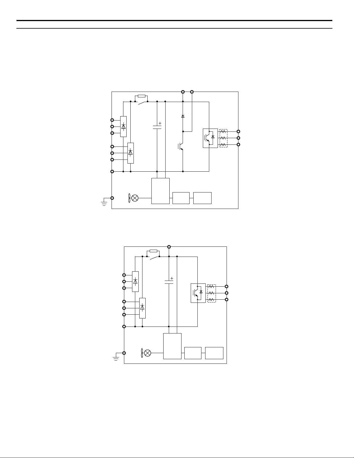
Main Circuit Connection Diagram
Refer to Figure 5, Figure 6, and Figure 7 when wiring the main circuit of the drive. Connections may vary based on drive
capacity.
NOTICE: Do not use the negative DC bus terminal “⊖” as a ground terminal. This terminal is at high DC voltage potential. Improper wiring
connections could damage the drive.
6-Phase/12-Pulse Input 400 V Class Models 4T0058o and 4T0072o
n
Figure 5 Connecting Main Circuit Terminals
6-Phase/12-Pulse Input 400 V Class Models 4T0088o to 4T0139o
n
Figure 6 Connecting Main Circuit Terminals
18
YASKAWA TOEP YAIA1U 02A YASKAWA AC Drive – A1000 6-Phase/12-Pulse Input Installation Manual
Gate
Board
Control
Board
Operator
24 V
Power
Supply
+3
R/L1
S/L2
T/L3
R1/L11
S1/L21
T1/L31
ー
U/T1
V/T2
W/T3
Relay
Current
Sensor
+
U/T1
V/T2
W/T3
R/L1
S/L2
T/L3
R1/L11
S1/L21
T1/L31
CDBR dynamic braking unit
(option) <2>
Dynamic braking resistor
(option) <1>
Motor
+3
-
Main Circuit
Power Supply
6-Phase/12-Pulse
Isolation Transformer
3-Phase Line Monitor
FuseBCP
Fuse
<3>
<4>
3 Electrical Installation
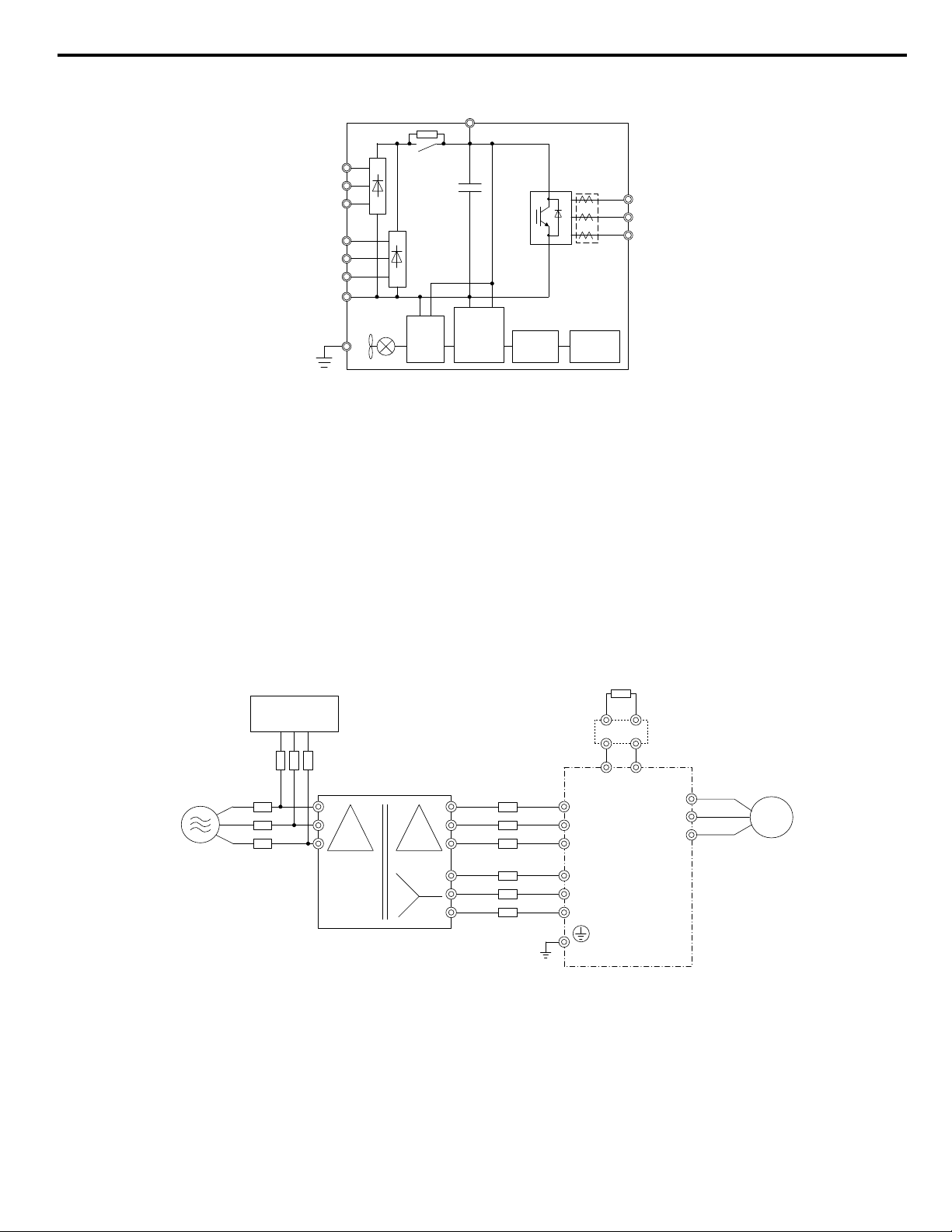
6-Phase/12-Pulse Input 400 V Class Models 4T0165o to 4T0675o
n
Figure 7 Connecting Main Circuit Terminals
6-Phase/12-Pulse Rectification
n
Installing a Transformer
Install a 6-Phase/12-Pulse isolation transformer with output windings phase-shifted by 30 electrical degrees or install a Hybrid
6-Phase topology on the power supply.
Installing a 3-Phase Line Monitor
Yaskawa requires installation of a 3-Phase line monitor to protect the drive in the event of an input line phase loss.
The 3-Phase line monitor must be installed on the primary circuit of the 6-Phase/12-Pulse transformer and connected to the
drive to remove the Run command when a phase loss condition occurs.
The drive power circuit may be damaged during a phase-loss condition if a 3-Phase line monitor is not properly installed.
Contact a Yaskawa representative for help selecting the optimum 3-Phase line monitor and fuses.
Connection Diagram
Figure 8 Main Circuit Terminal Connections
<1> A dynamic braking resistor can be connected to the B1 and B2 terminals on models 4T0058o and 4T0072o.
<2> A CDBR dynamic braking unit cannot be connected to models 4T0058o or 4T0072o.
<3> Refer to local codes for proper branch circuit protection (BCP) on the primary side of the 6-Phase/12-Pulse transformer.
<4> Fuse selection for the secondary side is of the 6-Phase/12-Pulse transformer is shown in Table 13 and Table 14
YASKAWA TOEP YAIA1U 02A YASKAWA AC Drive – A1000 6-Phase/12-Pulse Input Installation Manual
19
S1/L21
R1/L11
T1/L31
T/L3
U/T1
R/L1
S/L2
V/T2
W/T3
B1 B2
3
R/L1 S/L2 T/L3 R1/L11 S1/L21 T1/L31 U/T1 V/T2 W/T3
R/L1
S/L2
T/L3
R1/L11
U/T1 W/T3V/T2
S1/L21
T1/L31
3
3 Electrical Installation
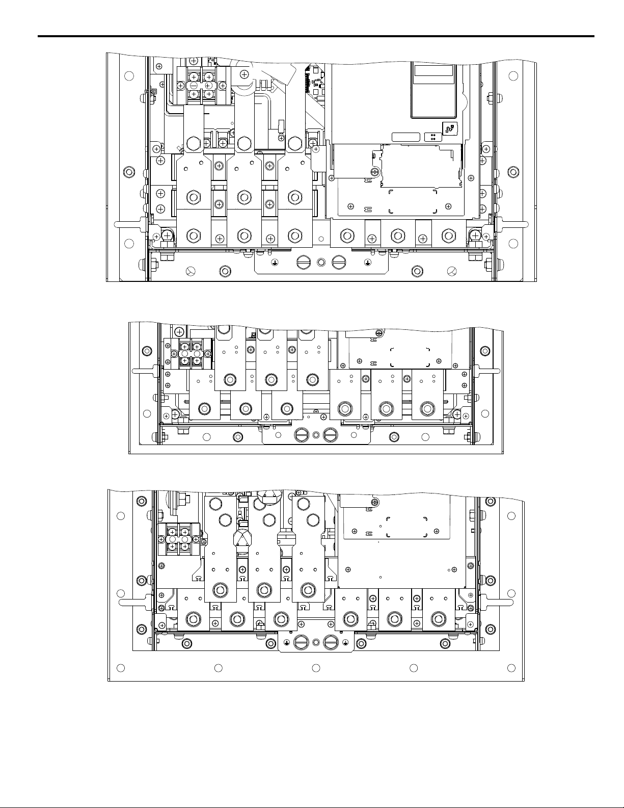
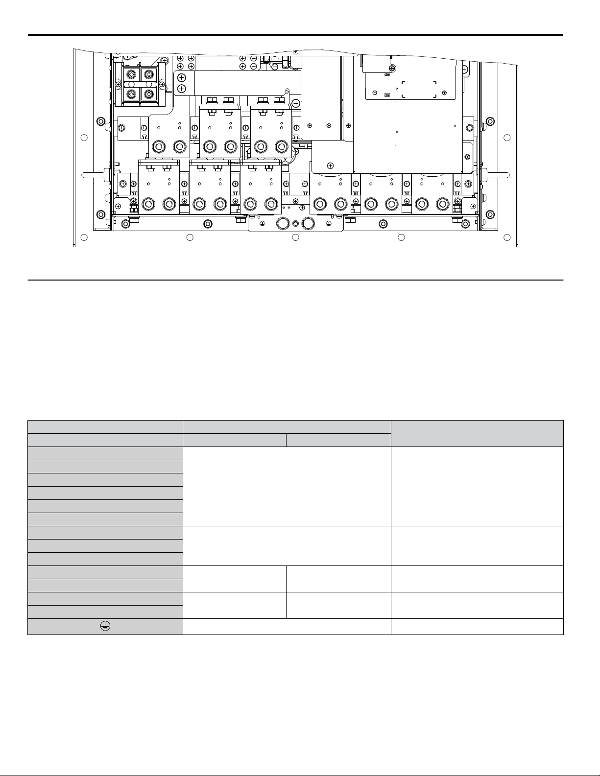
u
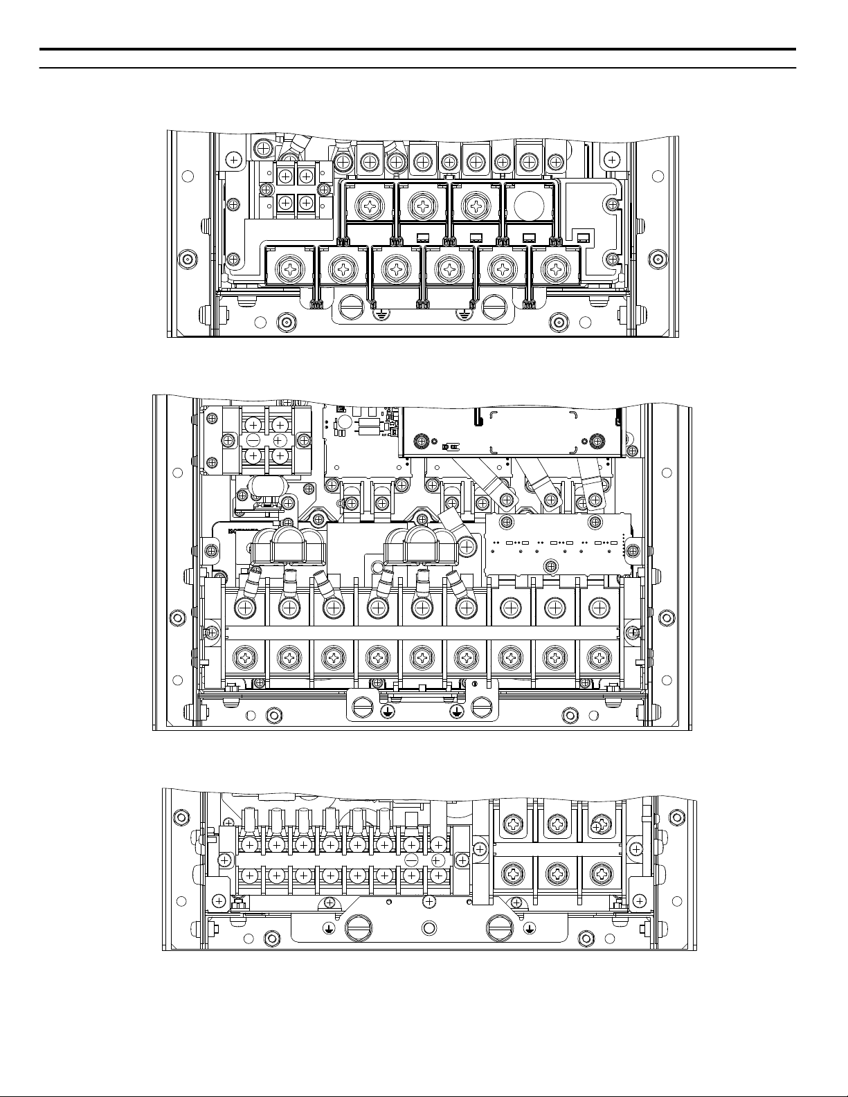
Terminal Specifications
Figure 9 to Figure 15 show the different terminal arrangements for the drive capacities.
Figure 9 Model 4T0058o and 4T0072o Terminals
20
Figure 10 Models 4T0088o and 4T0103o Terminals
Figure 11 Models 4T0139o and 4T0165o Terminals
YASKAWA TOEP YAIA1U 02A YASKAWA AC Drive – A1000 6-Phase/12-Pulse Input Installation Manual
R1/L11
S1/L21
T1/L31
R/L1
S/L2
T/L3
U/T1
V/T2
W/T3
3
Figure 12 Model 4T0208o Terminals
R1/L11
S1/L21
T1/L31
R/L1
S/L2
T/L3
U/T1
V/T2
W/T3
+3
-
R1/L11
S1/L21
T1/L31
R/L1
S/L2
T/L3
U/T1
V/T2
W/T3
+3
-
3 Electrical Installation
Figure 13 Models 4T0250o to 4T0362o Terminals
Figure 14 Model 4T0414o Terminals
YASKAWA TOEP YAIA1U 02A YASKAWA AC Drive – A1000 6-Phase/12-Pulse Input Installation Manual
21
R1/L11
S1/L21
T1/L31
R/L1
S/L2
T/L3
U/T1
V/T2
W/T3
+3
-
3 Electrical Installation
Figure 15 Models 4T0515o and 4T0675o Terminals
u
Main Circuit Wiring
This section describes the functions, specifications, and procedures required to safely and properly wire the main circuit in
the drive.
NOTICE: Do not solder the ends of wire connections to the drive. Soldered wiring connections can loosen over time. Improper wiring practices
could result in drive malfunction due to loose terminal connections.
NOTICE: Do not switch the drive input to start or stop the motor. Frequently switching the drive on and off shortens the life of the DC bus
charge circuit and the DC bus capacitors, and can cause premature drive failures. For the full performance life, refrain from switching the
drive on and off more than once every 30 minutes.
Main Circuit Terminal Functions
n
Table 4 Main Circuit Terminal Functions
Terminal Type
Model
R/L1
S/L2
T/L3
R1/L11
S1/L21
T1/L31
U/T1
W/T3
B1
B2
⊖
⊕3
Note: Note: DC power supply input is not available for 6-Phase/12-Pulse Input models.
Main Circuit Fuses
n
4T0058o and 4T0072o 4T0088o to 4T0675o
Main circuit power supply input Not available Connects line power to the drive
Drive output Connects to the motorV/T2
Braking resistor Not available
Not available
10 Ω or less Grounding terminal
Braking unit connection
(⊕3 and ⊖)
Available for connecting a braking resistor or a
braking resistor unit option
Only for connecting dynamic braking options
Function
The 6-Phase/12-Pulse drive requires fuses to be installed on each of the 6 input phases between the 6-Phase/12- Pulse
transformer and the drive. Select fuses from Table 13 or Table 14 according to drive model to maintain standards compliance.
22
YASKAWA TOEP YAIA1U 02A YASKAWA AC Drive – A1000 6-Phase/12-Pulse Input Installation Manual

3 Electrical Installation
u
Wire Gauges and Tightening Torques
Use the tables in this section to select the appropriate wires and crimp terminals.
Gauges listed in the tables are for use in the United States.
Note: 1. Wire gauge recommendations based on drive continuous current ratings (ND) using 75 °C 600 Vac vinyl-sheathed wire assuming ambient
temperature within 40 °C and wiring distance shorter than 100 m.
2. Terminals ⊕3 and ⊖ are for connecting optional power devices. Use caution to connect only approved devices to the correct terminal(s).
• Consider the amount of voltage drop when selecting wire gauges. Increase the wire gauge when the voltage drop is greater
than 2% of motor rated voltage. Ensure the wire gauge is suitable for the terminal block. Use the following formula to
calculate the amount of voltage drop:
Line drop voltage (V) = 3 × wire resistance (Ω/km) × wire length (m) × current (A) × 10
-3
• Refer to CDBR manual TOBP C720600 00/TOBP C720600 01 for dynamic braking wire gauges.
• Use terminals ⊕3 and ⊖ when connecting a CDBR dynamic braking unit.
• Do not connect a regenerative converter or a regenerative unit to the 6-Phase/12-Pulse drive.
• Refer to UL Standards on page 84 for information on UL compliance.
Yaskawa recommends using closed-loop crimp terminals on all drive models. UL/cUL approval requires the use of closedloop crimp terminals when wiring the drive main circuit terminals. Use only the tools recommended by the terminal
manufacturer for crimping. Refer to Closed-Loop Crimp Terminal Size on page 86 for closed-loop crimp terminal
recommendations.
The wire gauges listed in Table 5 are Yaskawa recommendations and are based on the 6-Phase input current ratings specified
in Table 14. Refer to local codes for proper wire gauge selections.
Drive Model
4T0058o
4T0072o
4T0088o
4T0103o
4T0139o
4T0165o
4T0208o
Table 5 Wire Gauge and Torque Specifications
Terminal
R/L1, S/L2, T/L3
R1/L11, S1/L21, T1/L31
U/T1, V/T2, W/T3
B1, B2 22 to 10 (0.3 to 5.3) M4 1.2 (10.6)
Refer to applicable codes for wire size M8
R/L1, S/L2, T/L3
R1/L11, S1/L21, T1/L31
U/T1, V/T2, W/T3
B1, B2 22 to 10 (0.3 to 5.3) M4 1.2 (10.6)
Refer to applicable codes for wire size M8
R/L1, S/L2, T/L3
U/T1, V/T2, W/T3
⊖, ⊕3
Refer to applicable codes for wire size M8 9 to 11 (79.7 to 97.4)
R/L1, S/L2, T/L3
R1/L11, S1/L21, T1/L31
⊖, ⊕3
U/T1, V/T2, W/T3 6 to 250 (13.3 to 127) M8 15.0 (132.8)
Refer to applicable codes for wire size M10
R/L1, S/L2, T/L3
R1/L11, S1/L21, T1/L31
U/T1, V/T2, W/T3
⊖, ⊕3
Refer to applicable codes for wire size M10
Refer to applicable codes for wire size M10
Wire Range
AWG, kcmil
10 to 1/0 (5.3 to 53.5) M8
10 to 3/0 (5.3 to 85.0) M8
6 to 250 (13.3 to 127) M8 9 to 11 (79.7 to 97.4)R1/L11, S1/L21, T1/L31
22 to 1/0 (0.3 to 53.5) M6 2.5 to 3.0 (22.1 to 26.6)
22 to 1/0 (0.3 to 53.5) M6
22 to 1/0 (0.3 to 53.5) M6
Screw
Size
Tightening Torque
N·m (lb.in.)
9 to 11
(79.7 to 97.4)
9 to 11
(79.7 to 97.4)
9 to 11
(79.7 to 97.4)
9 to 11
(79.7 to 97.4)
2.5 to 3.0
(22 to 1/0)
18 to 23
(159.3 to 203.6)
18 to 23
(159.3 to 203.6)
2.5 to 3.0
(22.1 to 26.6)
18 to 23
(159.3 to 203.6)
YASKAWA TOEP YAIA1U 02A YASKAWA AC Drive – A1000 6-Phase/12-Pulse Input Installation Manual
23
3 Electrical Installation
Drive Model Terminal
R/L1, S/L2, T/L3
R1/L11, S1/L21, T1/L31
U/T1, V/T2, W/T3
4T0250o
⊖, ⊕3
R/L1, S/L2, T/L3
R1/L11, S1/L21, T1/L31
U/T1, V/T2, W/3 M12
4T0296o
⊖, ⊕3
R/L1, S/L2, T/L3
R1/L11, S1/L21, T1/L31
U/T1, V/T2, W/T3 M12
4T0362o
⊖, ⊕3
R/L1, S/L2, T/L3
R1/L11, S1/L21, T1/L31
U/T1, V/T2, W/T3
4T0414o
⊖, ⊕3
R/L1, S/L2, T/L3
R1/L11, S1/L21, T1/L31
U/T1, V/T2, W/T3
4T0515o
⊖, ⊕3
R/L1, S/L2, T/L3
R1/L11, S1/L21, T1/L31
U/T1, V/T2, W/T3
4T0675o
⊖, ⊕3
Wire Range
AWG, kcmil
Refer to applicable codes for wire size M10
22 to 1/0 (0.3 to 53.5) M6
Refer to applicable codes for wire size M10
Refer to applicable codes for wire size
22 to 1/0 (0.3 to 53.5) M6
Refer to applicable codes for wire size M12
Refer to applicable codes for wire size
22 to 1/0 (0.3 to 53.5) M6
Refer to applicable codes for wire size M12
Refer to applicable codes for wire size M12
22 to 1/0 (0.3 to 53.5) M6
Refer to applicable codes for wire size M12
Refer to applicable codes for wire size M12
13.3 to 127 (6 to 250) M8
Refer to applicable codes for wire size M12
Refer to applicable codes for wire size M12
13.3 to 127 (6 to 250) M8
Refer to applicable codes for wire size M12
Screw
Size
M10
M10
Tightening Torque
N·m (lb.in.)
18 to 23
(159.3 to 203.6)
2.5 to 3.0
(22.1 to 26.6)
18 to 23
(159.3 to 203.6)
18 to 23
(159.3 to 203.6)
32 to 40
(283.2 to 354.0)
2.5 to 3.0
(22.1 to 26.6)
32 to 40
(283.2 to 354.0)
18 to 23
(159.3 to 203.6)
32 to 40
(283.2 to 354.0)
2.5 to 3.0
(22.1 to 26.6)
32 to 40
(283.2 to 354.0)
32 to 40
(283.2 to 354.0)
2.5 to 3.0
(22.1 to 26.6)
32 to 40
(283.2 to 354.0)
32 to 40
(283.2 to 354.0)
13.5 to 15
(119.5 to 132.8)
32 to 40
(283.2 to 354.0)
32 to 40
(283.2 to 354.0)
13.5 to 15
(119.5 to 132.8)
32 to 40
(283.2 to 354.0)
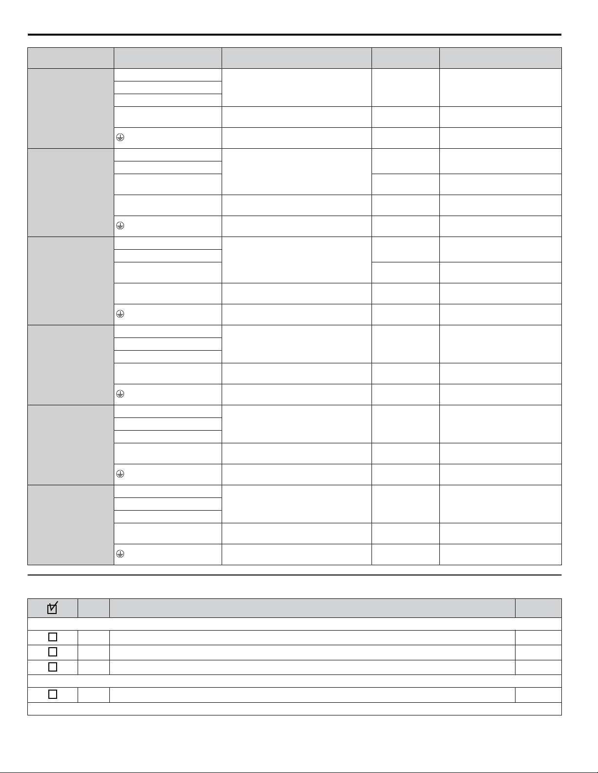
u
Wiring Checklist
No.
1 Check drive model number to ensure receipt of correct model. 10
2 Make sure you have the correct braking resistors, DC link chokes, noise filters, and other peripheral devices.
3 Check the option card model number.
4 Ensure that the area surrounding the drive complies with specifications. 13
24
Item Page(s)
Drive, Peripherals, Option Cards
Installation Area and Physical Setup
Power Supply Voltage, Output Voltage
YASKAWA TOEP YAIA1U 02A YASKAWA AC Drive – A1000 6-Phase/12-Pulse Input Installation Manual
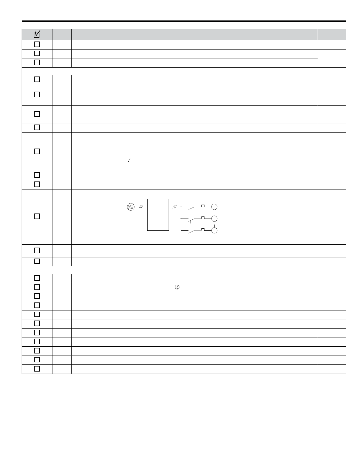
3 Electrical Installation
No. Item Page(s)
5 The voltage from the power supply should be within the input voltage specification range of the drive. –
6 The voltage rating for the motor should match the drive output specifications.
7 Verify that the drive is properly sized to run the motor.
Main Circuit Wiring
8 Confirm proper branch circuit protection as specified by national and local codes. 15
Properly wire the power supply to drive terminals R/L1, S/L2, T/L3, R1/L11, S1/L21, and T1/L31.
9
Note: Confirm that a 6-Phase/12-Pulse isolation transformer with each of the output windings phase-shifted
by 30 electrical degrees or a Hybrid 6-Phase topology is installed on the power supply.
Properly wire the drive and motor together.
10
The motor lines and drive output terminals U/T1, V/T2, and W/T3 should match in order to produce the desired phase
order. If the phase order is incorrect, the drive will rotate in the opposite direction.
11 Use 600 Vac vinyl-sheathed wire for the power supply and motor lines. 23
Use the correct wire gauges for the main circuit.
• Consider the amount of voltage drop when selecting wire gauges. Increase the wire gauge when the voltage drop is
12
greater than 2% of motor rated voltage. Ensure the wire gauge is suitable for the terminal block. Use the following
formula to calculate the amount of voltage drop:
Line drop voltage (V) = 3 × wire resistance (Ω/km) × wire length (m) × current (A) × 10
-3
• If the cable between the drive and motor exceeds 50 m, adjust the carrier frequency set to C6-02 accordingly.
13 Properly ground the drive. –
14 Tighten control circuit and grounding terminal screws. 23
Set up overload protection circuits when running multiple motors from a single drive.
Power supply
15
Drive
MC1
MC2
MCn
OL1
OL2
OLn
M1
M2
Mn
MC1 — MCn
OL 1 — OLn
… magnetic contactor
… thermal relay
10
18
–
23
–
Note: Close MC1 – MCn before operating the drive. MC1 – MCn cannot be switched off during run.
Install a magnetic contactor when using a dynamic braking option. Properly install the resistor and ensure that overload
16
protection shuts off the power supply using the magnetic contactor.
17 Verify phase advancing capacitors, input noise filters, or GFCIs are NOT installed on the output side of the drive. –
Control Circuit Wiring
18 Use twisted-pair line for all drive control circuit wiring. –
19
Ground the shields of shielded wiring to the GND terminal.
20 For 3-Wire sequence, set parameters for multi-function contact input terminals S1 – S8, and wire control circuits. –
21 Properly wire any option cards. –
22 Check for any other wiring mistakes. Only use a multimeter to check wiring. –
23 Properly fasten drive control circuit terminal screws. 23
24 Pick up all wire clippings. –
25 Ensure that no frayed wires on the terminal block are touching other terminals or connections. –
26 Properly separate control circuit wiring and main circuit wiring. –
27 Analog signal line wiring should not exceed 50 m. –
28 Safe Disable input wiring should not exceed 30 m. –
–
–
YASKAWA TOEP YAIA1U 02A YASKAWA AC Drive – A1000 6-Phase/12-Pulse Input Installation Manual
25

4 Start-Up Programming & Operation
4 Start-Up Programming & Operation
u
Powering Up the Drive
Review the following checklist before applying power.
Item to Check Description
6-Phase/12-Pulse Isolated 380 to 480 Vac 50/60 Hz, 30 electrical degrees phase-shifted each phase
Power supply
Drive output terminals and
motor terminals
Control circuit terminals Check control circuit terminal connections.
Drive control terminal status Open all control circuit terminals (off).
Status of the load and connected
machinery
<1> Install a 6-Phase/12-Pulse isolation transformer with each of the output windings phase-shifted by 30 electrical degrees or use a Hybrid 6-Phase
topology.
Properly wire the power supply input terminals (R/L1, S/L2, T/L3, R1/L11, S1/L21, T1/L31).
Check for proper grounding of drive and motor.
Properly wire drive output terminals U/T1, V/T2, and W/T3 with motor terminals U, V, and W.
Decouple the motor from the load.
<1>
26
YASKAWA TOEP YAIA1U 02A YASKAWA AC Drive – A1000 6-Phase/12-Pulse Input Installation Manual

5 Troubleshooting
5 Troubleshooting
NOTICE
Refer to the A1000 Technical Manual SIEP C710616 41 for information on Troubleshooting and complete product
instructions necessary for proper installation, set-up, troubleshooting and maintenance.
The A1000 Technical Manual is posted on the Yaskawa website, www.yaskawa.com.
WARNING
Electrical Shock Hazard
Do not connect or disconnect wiring while the power is on.
Failure to comply could result in death or serious injury.
Before servicing, disconnect all power to the equipment. The internal capacitor remains charged even after the power supply
is turned off. The charge indicator LED will extinguish when the DC bus voltage is below 50 Vdc. To prevent electric shock,
wait for at least the time specified on the warning label; after all indicators are OFF, measure for unsafe voltages to confirm
the drive is safe prior to servicing.
Do not operate equipment with covers removed.
Failure to comply could result in death or serious injury.
The diagrams in this section may illustrate drives without covers or safety shields to display details. Be sure to reinstall covers
or shields before operating the drives and run the drives according to the instructions described in this manual.
Do not touch terminals before the capacitors have fully discharged.
Failure to comply could result in death or serious injury.
Before servicing, disconnect all power to the equipment. The internal capacitor remains charged even after the power supply
is turned off. The charge indicator LED will extinguish when the DC bus voltage is below 50 Vdc. To prevent electric shock,
wait for at least the time specified on the warning label; after all indicators are OFF, measure for unsafe voltages to confirm
the drive is safe prior to servicing.
After blowing a fuse or tripping a GFCI, do not attempt to restart the drive or operate peripheral devices until five
minutes pass and CHARGE lamp is OFF.
Failure to comply could result in death, serious injury, and damage to the drive.
Check wiring and peripheral device ratings to identify the cause of trips.
Contact your supplier if the cause cannot be identified.
Installation, maintenance, inspection and servicing must be performed only by authorized personnel familiar with installation,
adjustment and maintenance of AC drives.
Do not perform work on the drive while wearing loose clothing, jewelry, or without eye protection.
Failure to comply could result in death or serious injury.
Do not remove covers or touch circuit boards while the power is on.
Failure to comply could result in death or serious injury.
YASKAWA TOEP YAIA1U 02A YASKAWA AC Drive – A1000 6-Phase/12-Pulse Input Installation Manual
27

LO
RE
F2F1
ESC
RUN STOP
ENTERRESET
RESET
— MODE —
oC
Overcurrent
DRV
FWD
RESET
ALM
5 Troubleshooting
u
Fault Reset Methods
When a fault occurs, the cause of the fault must be removed and the drive must be restarted. The table below lists the different
ways to restart the drive.
After the Fault Occurs Procedure
Fix the cause of the fault, restart the drive, and
reset the fault
Resetting via Fault Reset Digital Input S4
Press on the digital operator when the error code
is displayed.
Close then open the fault signal digital input via
terminal S4. S4 is set for “Fault Reset” as default
(H1-04 = 14).
Fault Reset Switch
2
Drive
S4 Fault Reset Digital Input
SC Digital Input Common
ON
Turn off the main power supply if the above methods do not reset the fault. Reapply power after the
digital operator display has turned off.
1
OFF
Note: If the Run command is present, the drive will disregard any attempts to reset the fault. Remove the Run command before attempting to clear
a fault situation.
28
YASKAWA TOEP YAIA1U 02A YASKAWA AC Drive – A1000 6-Phase/12-Pulse Input Installation Manual
Loading…
-
Contents
-
Table of Contents
-
Troubleshooting
-
Bookmarks
Quick Links
YASKAWA AC Drive-A1000
High Performance Vector Control Drive
Quick Start Guide
Type: CIMR-AU A
Models: 200 V Class: 0.4 to 110 kW (3/4 to 175 HP ND)
400 V Class: 0.4 to 630 kW (3/4 to 1000 HP ND)
600 V Class: 0.75 to 75 kW (1 to 100 HP ND)
To properly use the product, read this manual thoroughly and retain
for easy reference, inspection, and maintenance. Ensure the end user
receives this manual.
MANUAL NO. TOEP C710616 41B
Troubleshooting
Summary of Contents for YASKAWA A1000
Преобразователь частоты A1000 – это преобразователь частоты высочайшего уровня от компании YASKAWA. Он обеспечивает надёжность эксплуатации, экологические выгоды и экономию электроэнергии, а также множество иных эксплуатационных характеристик, ориентированных на пользователя, что делает данный преобразователь частоты превосходным выбором.
- Работа двигателей с постоянными магнитами без энкодера с максимальным крутящем моментом при нулевой скорости
-
Улучшенные функции автонастройки для автоматической корректировки параметров двигателя и постоянного анализа изменений во время работы двигателя для достижения самой высокой производительности оборудование
-
Улучшенный технология управления энергосбережением, которая повышает КПД и производительность оборудования при совместной работе с асинхронным и синхронным двигателем
- Доступны особые характеристики для высокой скорости вращения, позиционирования, кранов и лебёдок, электронного трансмиссионного вала
Технические характеристики
|
Тип: |
Преобразователь частоты общего назначения высочайшего уровня |
|
Диапазон: |
0,55 кВт — 630 кВт |
|
Максимальная мощность двигателя (кВт): |
3~200 VAC, 0.4 – 110 |
|
Применимые двигатели: |
Асинхронный двигатель (IM) |
|
Управление: |
Управление напряжением/частотой |
|
Диапазон регулирования скорости: |
Управление напряжением/частотой и Управление напряжением/частотой с PG 1:40 |
|
Регулировка крутящего момента: |
Стандарт |
|
Максимальная выходная частота: |
400 Гц |
|
Интерфейсные шины: |
RS-232C |
|
Стандарты: |
CE |
|
Степень защиты корпуса: |
IP00, IP20, IP54, NEMA1 |
|
Функции: |
Выключатель управления скоростью/крутящим моментом |
- Бренд
- Yaskawa
- Страна
- Япония
- Сегмент
- Общепромышленные преобразователи частоты
- Тип
- Преобразователь частоты
- Конструкция
- Общепромышленное применение
- Гарантия
- 3 года
-
Общий каталог Yaskawa A1000.pdf
Размер: 3 Мб
-
Техническое руководство A1000.pdf
Размер: 61 Мб
-
Инструкция по запуску Yaskawa A1000.pdf
Размер: 5 Мб
-
Каталог Yaskawa A1000+DriveWorkEZ 1.0.pdf
Размер: 9 Мб
- Manuals
- Brands
- YASKAWA Manuals
- Controller
- A1000 Series
Manuals and User Guides for YASKAWA A1000 Series. We have 16 YASKAWA A1000 Series manuals available for free PDF download: Technical Manual, Quick Start Manual, Installation Manual, Product Replacement Manual, Manual, Setup
YASKAWA A1000 Series Technical Manual (544 pages)
High Performance Vector Control Drive Models: 200 V Class: 0.4 to 110 kW 400 V Class: 0.4 to 355 kW
Brand: YASKAWA
|
Category: Controller
|
Size: 56.82 MB
Table of Contents
-
-
-
Applicable Documentation
16
-
Terms and Abbreviations
16
-
-
-
Supplemental Safety Information
17
-
Notes on Motor Operation
21
-
Applications with Specialized Motors
22
-
-
-
-
Control Mode Selection
28
-
Model Number and Nameplate Check
29
-
Drive Models and Enclosure Types
31
-
-
IP20/NEMA Type 1 Enclosure
32
-
-
Mechanical Installation
37
-
Installation Environment
40
-
2 Mechanical Installation
40
-
Installation Orientation and Spacing
40
-
Digital Operator Remote Usage
42
-
Exterior and Mounting Dimensions
46
-
-
Electrical Installation
51
-
Standard Connection Diagram
54
-
Main Circuit Connection Diagram
56
-
Three-Phase 200 V Class (CIMR-A 2A0169 to
56
-
Three-Phase 400 V Class (CIMR-A 4A0088 to 0675)
56
-
Terminal Block Configuration
57
-
-
CIMR-A 2A0004 to 0081, 4A0002 to 0044 (IP20/NEMA Type 1 Enclosure)
59
-
CIMR-A 2A0110 to 0415, 4A0058 to 0675 (IP00 Enclosure)
60
-
Removing/Reattaching the Digital Operator
61
-
Removing/Reattaching the Front Cover
61
-
-
Removing the Top Protective Cover
64
-
Reattaching the Top Protective Cover
64
-
-
-
Main Circuit Terminal Functions
65
-
Protecting Main Circuit Terminals
65
-
Wire Gauges and Tightening Torque
66
-
Main Circuit Terminal and Motor Wiring
70
-
Control Circuit Wiring
72
-
-
Control Circuit Connection Diagram
72
-
Control Circuit Terminal Block Functions
72
-
Terminal Configuration
73
-
Wiring the Control Circuit Terminal
74
-
Switches and Jumpers on the Terminal Board
76
-
Control I/O Connections
77
-
-
Sinking/Sourcing Mode Selection for Safe Disable Inputs
77
-
Sinking/Sourcing Mode Switch for Digital Inputs
77
-
Using the Pulse Train Output
78
-
Terminal A2 Input Signal Selection
79
-
Terminal A3 Analog/Ptc Input Selection
79
-
Terminal AM/FM Signal Selection
79
-
Memobus/Modbus Termination
80
-
Start-Up Programming & Operation
85
-
Using the Digital Operator
87
-
ALARM (ALM) LED Displays
89
-
LO/RE LED and RUN LED Indications
89
-
Menu Structure for Digital Operator
90
-
The Drive and Programming Modes
91
-
Navigating the Drive and Programming Modes
91
-
Changing Parameter Settings or Values
92
-
Verifying Parameter Changes: Verify Menu
94
-
Simplified Setup Using the Setup Group
95
-
Switching between LOCAL and REMOTE
96
-
Flowchart A: Basic Start-Up and Motor Tuning
98
-
Subchart A-1: Simple Motor Setup Using V/F Control
99
-
Subchart A-2: High Performance Operation Using OLV or CLV
100
-
Subchart A-3: Operation with Permanent Magnet Motors
101
-
Powering up the Drive
102
-
Powering up the Drive and Operation Status Display
102
-
Application Selection
103
-
Setting 1: Water Supply Pump Application
103
-
Setting 2: Conveyor Application
103
-
Setting 3: Exhaust Fan Application
104
-
Setting 4: HVAC Fan Application
104
-
Setting 5: Compressor Application
105
-
Setting 6: Hoist Application
105
-
Notes on Controlling the Brake When Using the Hoist Application Preset
106
-
Setting 7: Traveling Application
108
-
Before Auto-Tuning the Drive
111
-
Auto-Tuning Interruption and Fault Codes
112
-
Auto-Tuning Operation Example
112
-
Parameter Settings During Induction Motor Auto-Tuning: T1
114
-
Parameter Settings During PM Motor Auto-Tuning: T2
116
-
Parameter Settings During Inertia and Speed Control Loop Auto-Tuning: T3
119
-
No-Load Operation Test Run
121
-
Test Run with Load Connected
123
-
Test Run with the Load Connected
123
-
Verifying Parameter Settings and Backing up Changes
124
-
Backing up Parameter Values: O2-03
124
-
Parameter Access Level: A1-01
124
-
Password Settings: A1-04, A1-05
124
-
-
-
B1: Operation Mode Selection
136
-
B2: DC Injection Braking and Short Circuit Braking
144
-
B7: Droop Control (CLV, CLV/PM)
162
-
C1: Acceleration and Deceleration Times
165
-
C2: S-Curve Characteristics
167
-
C3: Slip Compensation
167
-
C4: Torque Compensation
170
-
C5: Automatic Speed Regulator (ASR)
171
-
C6: Carrier Frequency
177
-
D: Reference Settings
180
-
-
D1: Frequency Reference
180
-
D2: Frequency Upper/Lower Limits
182
-
D4: Frequency Reference Hold and Up/Down 2 Function
183
-
D6: Field Weakening and Field Forcing
192
-
E1: V/F Pattern for Motor 1
194
-
E2: Motor 1 Parameters
198
-
E3: V/F Pattern for Motor 2
201
-
E4: Motor 2 Parameters
202
-
E5: PM Motor Settings
204
-
F1: PG Speed Control Card Settings
206
-
F2: Analog Input Card Settings
209
-
F3: Digital Input Card Settings
209
-
F4: Analog Monitor Card Settings
210
-
F5: Digital Output Card Settings
211
-
F6: Communication Option Card
211
-
-
H: Terminal Functions
214
-
-
MECHATROLINK Parameters
213
-
PROFIBUS-DP Parameters
213
-
H1: Multi-Function Digital Inputs
214
-
H2: Multi-Function Digital Outputs
224
-
H3: Multi-Function Analog Inputs
234
-
H4: Multi-Function Analog Outputs
239
-
H5: Memobus/Modbus Serial Communication
241
-
H6: Pulse Train Input/Output
241
-
L: Protection Functions
244
-
-
L2: Momentary Power Loss Ride-Thru
249
-
-
N: Special Adjustments
275
-
-
N1: Hunting Prevention
275
-
N2: Speed Feedback Detection Control (AFR) Tuning
276
-
N3: High Slip Braking (HSB) and Overexcitation Braking
276
-
N5: Feed Forward Control
279
-
N8: PM Motor Control Tuning
281
-
O: Operator Related Settings
284
-
-
O1: Digital Operator Display Selection
284
-
O2: Digital Operator Keypad Functions
285
-
O4: Maintenance Monitor Settings
288
-
Q: Driveworksez Parameters
289
-
R: Driveworksez Connection Parameters
289
-
U: Monitor Parameters
291
-
-
U1: Operation Status Monitors
291
-
U4: Maintenance Monitors
291
-
U6: Operation Status Monitors
291
-
U8: Driveworksez Monitors
292
-
-
Fine-Tuning Open Loop Vector Control
296
-
Fine-Tuning V/F Control and V/F Control with PG
296
-
Motor Performance Fine-Tuning
296
-
Fine-Tuning Closed Loop Vector Control
297
-
Fine-Tuning Open Loop Vector Control for PM Motors
297
-
Fine-Tuning Advanced Open Loop Vector Control for PM Motors
298
-
Fine-Tuning Closed Loop Vector Control for PM Motors
298
-
Parameters to Minimize Motor Hunting and Oscillation
299
-
Drive Alarms, Faults, and Errors
300
-
Types of Alarms, Faults, and Errors
300
-
-
Alarm and Error Displays
301
-
Fault Displays, Causes, and Possible Solutions
306
-
Alarm Codes, Causes, and Possible Solutions
319
-
Operator Programming Errors
325
-
-
Ope Codes, Causes, and Possible Solutions
325
-
Auto-Tuning Fault Detection
328
-
-
Auto-Tuning Codes, Causes, and Possible Solutions
328
-
Copy Function Related Displays
332
-
-
Tasks, Errors, and Troubleshooting
332
-
Diagnosing and Resetting Faults
334
-
-
Fault Occurs Simultaneously with Power Loss
334
-
If the Drive Still Has Power after a Fault Occurs
334
-
Viewing Fault Trace Data after Fault
334
-
-
Troubleshooting Without Fault Display
336
-
Cannot Change Parameter Settings
336
-
Motor Does Not Rotate Properly after Pressing RUN Button or after
336
-
Entering External Run Command
337
-
Drive Does Not Allow Selection the Desired Auto-Tuning Mode
338
-
Ope02 Error Occurs When Lowering the Motor Rated Current Setting
338
-
Motor Stalls During Acceleration or Acceleration Time Is too Long
338
-
Excessive Motor Oscillation and Erratic Rotation
339
-
Deceleration Takes Longer than Expected with Dynamic Braking Enabled
339
-
Load Falls When Brake Is Applied (Hoist-Type Applications)
339
-
Noise from Drive or Output Lines When the Drive Is Powered on
340
-
Earth Leakage Circuit Breaker (ELCB) Trips During Run
340
-
Connected Machinery Vibrates When Motor Rotates
340
-
Insufficient Starting Torque
340
-
Output Frequency Is Not as High as Frequency Reference
341
-
Buzzing Sound from Motor at 2 Khz
341
-
Unstable Motor Speed When Using PM
341
-
Motor Does Not Restart after Power Loss
341
-
Advertisement
YASKAWA A1000 Series Technical Manual (628 pages)
High Performance Vector Control Drive
Type: CIMR-A series
Models: 200 V Class: 0.55 to 110 kW,
400 V Class: 0.55 to 630 kW
Brand: YASKAWA
|
Category: Controller
|
Size: 55.44 MB
Table of Contents
-
-
YASKAWA ELECTRIC SIEP C710616 27G YASKAWA AC Drive A1000 Technical Manual
13
-
Applicable Documentation
16
-
Notes on Motor Operation
23
-
Applications with Specialized Motors
24
-
-
-
Model Number and Nameplate Check
32
-
Drive Models and Enclosure Types
33
-
Drive Models and Enclosure Types
34
-
2 Mechanical Installation
43
-
Mechanical Installation
48
-
Digital Operator Remote Usage
50
-
Exterior and Mounting Dimensions
52
-
-
Electrical Installation
57
-
Standard Connection Diagram
60
-
Standard Connection Diagram
62
-
Main Circuit Configurations
63
-
Main Circuit Configurations
65
-
Terminal Block Configuration
66
-
Terminal Block Configuration
67
-
Digital Operator and Front Cover
71
-
Protecting Main Circuit Terminals
76
-
Main Circuit Terminal and Motor Wiring
81
-
Control Circuit Wiring
83
-
-
Terminal Configuration
84
-
Wiring the Control Circuit Terminal
85
-
Switches and Jumpers on the Terminal Board
87
-
Control I/O Connections
88
-
-
Using the Pulse Train Output
89
-
Terminal A2 Input Signal Selection
90
-
Memobus/Modbus Termination
91
-
Start-Up Programming & Operation
97
-
Using the Digital Operator
99
-
ALARM (ALM) LED Displays
101
-
Menu Structure for Digital Operator
102
-
The Drive and Programming Modes
103
-
-
Changing Parameter Settings or Values
105
-
Verifying Parameter Changes: Verify Menu
106
-
Simplified Setup Using the Setup Group
107
-
Switching between LOCAL and REMOTE
108
-
Subchart A-1: Simple Motor Setup Using V/F Control
110
-
Subchart A-2: High Performance Operation Using OLV or CLV
111
-
Subchart A-3: Operation with Permanent Magnet Motors
112
-
Powering up the Drive
113
-
Application Selection
114
-
Setting 2: Conveyor Application
115
-
Setting 5: Compressor Application
116
-
Notes on Controlling the Brake When Using the Hoist Application Preset
117
-
Setting 7: Traveling Application
119
-
Before Auto-Tuning the Drive
123
-
Auto-Tuning Interruption and Fault Codes
125
-
Parameter Settings During Induction Motor Auto-Tuning: T1
127
-
Parameter Settings During PM Motor Auto-Tuning: T2
130
-
Parameter Settings During Inertia and Speed Control Loop Auto-Tuning: T3
132
-
No-Load Operation Test Run
134
-
Test Run with Load Connected
136
-
Verifying Parameter Settings and Backing up Changes
137
-
-
B2: DC Injection Braking and Short Circuit Braking
158
-
C2: S-Curve Characteristics
185
-
C4: Torque Compensation
188
-
C5: Automatic Speed Regulator (ASR)
190
-
C6: Carrier Frequency
195
-
D: Reference Settings
198
-
-
D2: Frequency Upper/Lower Limits
200
-
D4: Frequency Reference Hold and Up/Down 2 Function
201
-
D6: Field Weakening and Field Forcing
210
-
E2: Motor 1 Parameters
216
-
E3: V/F Pattern for Motor 2
219
-
E4: Motor 2 Parameters
220
-
E5: PM Motor Settings
222
-
F2: Analog Input Card Settings
228
-
F3: Digital Input Card Settings
229
-
F4: Analog Monitor Card Settings
230
-
F5: Digital Output Card Settings
231
-
H: Terminal Functions
235
-
-
H2: Multi-Function Digital Outputs
246
-
H3: Multi-Function Analog Inputs
257
-
H4: Multi-Function Analog Outputs
262
-
H5: Memobus/Modbus Serial Communication
264
-
L: Protection Functions
267
-
-
L2: Momentary Power Loss Ride-Thru
274
-
L9: Drive Protection 2
301
-
N: Special Adjustments
302
-
-
N2: Speed Feedback Detection Control (AFR) Tuning
303
-
N5: Feed Forward Control
306
-
N8: PM Motor Control Tuning
308
-
O: Operator Related Settings
314
-
-
O2: Digital Operator Keypad Functions
315
-
-
Q: Driveworksez Parameters
320
-
U: Monitor Parameters
321
-
-
-
Motor Performance Fine-Tuning
326
-
Fine-Tuning Closed Loop Vector Control
327
-
Fine-Tuning Advanced Open Loop Vector Control for PM Motors
328
-
Parameters to Minimize Motor Hunting and Oscillation
329
-
Drive Alarms, Faults, and Errors
330
-
Alarm and Error Displays
331
-
Operator Programming Errors
357
-
Causes and Possible Solutions for a Blank and Unresponsive Digital Operator
359
-
Auto-Tuning Fault Detection
360
-
Copy Function Related Displays
364
-
Diagnosing and Resetting Faults
366
-
Troubleshooting Without Fault Display
368
-
Motor Stalls During Acceleration or Acceleration Time Is too Long
371
-
Deceleration Takes Longer than Expected with Dynamic Braking Enabled
372
-
Unstable Motor Speed When Using PM
374
YASKAWA A1000 Series Quick Start Manual (358 pages)
High Performance Vector Control Drive
Brand: YASKAWA
|
Category: Controller
|
Size: 14.79 MB
Table of Contents
-
Preface & General Safety
11
-
-
Applicable Documentation
12
-
-
-
Supplemental Safety Information
13
-
General Application Precautions
15
-
Motor Application Precautions
18
-
Drive Label Warning Example
20
-
-
-
-
Model Number and Nameplate Check
22
-
-
2 Mechanical Installation
27
-
Mechanical Installation
28
-
Installation Environment
28
-
Installation Orientation and Spacing
28
-
Instructions on Installation Using the Eye Bolts
30
-
-
Flange Type Enclosure (NEMA 12 Backside) Dimensions & Heat Loss
41
-
Flange Type Models 2A0004 to 2A0012, 4A0002 to 4A0005, and 5A0003 and 5A0004
41
-
Flange Type Models 2A0018 and 2A0021, 4A0007 to 4A0011, and 5A0006 and 5A0009
44
-
Flange Type Models 2A0030 and 2A0040, 4A0018 and 4A0023, and 5A0011
47
-
Flange Type Model 4A0031
50
-
Flange Type Models 2A0056, 4A0038, and 5A0017 and 5A0022
52
-
Flange Type Models 2A0069 and 2A0081, 4A0044, and 5A0027 and 5A0032
55
-
Flange Type Models 2A0110 and 4A0058
58
-
Flange Type Models 2A0138, 4A0072, and 5A0041 and 5A0052
60
-
Flange Type Models 4A0088 and 4A0103
62
-
Flange Type Models 2A0169 and 2A0211, 4A0139 and 4A0165, and 5A0062 to 5A0099
64
-
Flange Type Models 2A0250 and 2A0312, 4A0208, and 5A0125 and 5A0145
67
-
Flange Type Models 2A0360 and 2A0415, 4A0250 to 4A0362, and 5A0192 and 5A0242
69
-
Flange Type Model 4A0414
72
-
Flange Type Models 4A0515 and 4A0675
74
-
Flange Type Models 4A0930 and 4A1200
76
-
-
-
3 Electrical Installation
79
-
Standard Connection Diagram
80
-
Main Circuit Connection Diagram
83
-
Three-Phase 200 V Class Models 2A0004 to 2A0081 Three-Phase 400 V Class Models 4A0002 to 4A0044 Three-Phase 600 V Class Models 5A0003 to 5A0032
83
-
Three-Phase 200 V Class Models 2A0110, 2A0138 Three-Phase 400 V Class Models 4A0058, 4A0072 Three-Phase 600 V Class Models 5A0041, 5A0052
83
-
Three-Phase 200 V Class Models 2A0169 to 2A0211 Three-Phase 400 V Class Models 4A0088 to 4A0139 Three-Phase 600 V Class Models 5A0062 to 5A0099
84
-
Three-Phase 200 V Class Models 2A0250 to 2A0415 Three-Phase 400 V Class Models 4A0165 to 4A0675 Three-Phase 600 V Class Models 5A0125 to 5A0242
84
-
Three-Phase 400 V Class Models 4A0930, 4A1200
85
-
12-Pulse Rectification
85
-
-
-
Models 2A0004 to 2A0081, 4A0002 to 4A0044, 5A0003 to 5A0032 (IP20/NEMA 1, UL Type 1 Enclosure)
87
-
Models 2A0110 to 2A0250, 4A0208 to 4A1200, and 5A0125 to 5A0242 (Ip00/Open Type Enclosure)
88
-
-
-
Removing/Reattaching the Digital Operator
89
-
Removing/Reattaching the
89
-
-
-
Removing the Top Protective Cover
92
-
Reattaching the Top Protective Cover
92
-
-
-
Main Circuit Terminal Functions
93
-
Protecting Main Circuit Terminals
94
-
Main Circuit Wire Gauges and Tightening Torques
94
-
Main Circuit Terminal and Motor Wiring
103
-
-
Control Circuit Wiring
105
-
Control Circuit Terminal Block Functions
105
-
Terminal Configuration
107
-
Wiring the Control Circuit Terminal
108
-
-
Control I/O Connections
110
-
Sinking/Sourcing Mode for Digital Inputs
110
-
Sinking/Sourcing Mode Selection for Safe Disable Inputs
111
-
Using the Pulse Train Output
112
-
Terminal A2 Input Signal Selection
113
-
Terminal A3 Analog/Ptc Input Selection
113
-
Terminal AM/FM Signal Selection
113
-
Terminal DM+ and DM- Output Signal Selection
114
-
-
-
4 Start-Up Programming & Operation
119
-
Using the Digital Operator
120
-
Digital Operator Keys and Displays
120
-
ALARM (ALM) LED Displays
122
-
LO/RE LED and RUN LED Indications
122
-
Menu Structure for Digital Operator
123
-
-
The Drive and Programming Modes
124
-
Changing Parameter Settings or Values
124
-
Switching between LOCAL and REMOTE
126
-
-
-
Flowchart A: Basic Start-Up and Motor Tuning
128
-
Subchart A-1: Simple Motor Setup Using V/F Control
129
-
Subchart A-2: High Performance Operation Using OLV or CLV
130
-
Subchart A-3: Operation with Permanent Magnet Motors
131
-
-
Powering up the Drive
133
-
Powering up the Drive and Operation Status Display
133
-
-
Application Selection
134
-
Basic Drive Setup Adjustments
135
-
-
Auto-Tuning Interruption and Fault Codes
167
-
Auto-Tuning Operation Example
169
-
No-Load Operation Test Run
171
-
Test Run with Load Connected
173
-
Test Run with the Load Connected
173
-
-
-
-
Drive Alarms, Faults, and Errors
178
-
Types of Alarms, Faults, and Errors
178
-
-
-
Fault Displays, Causes, and Possible Solutions
179
-
-
-
Alarm Codes, Causes, and Possible Solutions
196
-
-
Operator Programming Errors
203
-
Operator Programming Error Codes, Causes, and Possible Solutions
203
-
Causes and Possible Solutions for a Blank and Unresponsive Digital Operator
204
-
-
Auto-Tuning Fault Detection
205
-
Auto-Tuning Codes, Causes, and Possible Solutions
205
-
-
Copy Function Related Displays
211
-
Tasks, Errors, and Troubleshooting
211
-
-
-
6 Periodic Inspection & Maintenance
213
-
-
Recommended Daily Inspection
214
-
Recommended Periodic Inspection
215
-
-
-
7 Peripheral Devices & Options
221
-
Option Card Installation
222
-
Prior to Installing the Option
222
-
PG Option Installation Example
223
-
-
-
-
Heavy Duty and Normal Duty Ratings
234
-
-
Three-Phase 200 V Class Drive Models 2A0004 to 2A0030
235
-
Three-Phase 200 V Class Drive Models 2A0040 to 2A0211
236
-
Three-Phase 200 V Class Drive Models 2A0250 to 2A0415
237
-
Three-Phase 400 V Class Drive Models 4A0002 to 4A0031
238
-
Three-Phase 400 V Class Drive Models 4A0038 to 4A0165
239
-
Three-Phase 400 V Class Drive Models 4A0208 to 4A1200
240
-
Three-Phase 600 V Class Drive Models 5A0003 to 5A0032
241
-
Three-Phase 600 V Class Drive Models 5A0041 to 5A0099
242
-
Three-Phase 600 V Class Drive Models 5A0125 to 5A0242
243
-
-
Advertisement
YASKAWA A1000 Series Technical Manual (257 pages)
Brand: YASKAWA
|
Category: Controller
|
Size: 14.89 MB
Table of Contents
-
Preface & General Safety
11
-
-
Applicable Documentation
12
-
-
-
Supplemental Safety Information
13
-
General Application Precautions
15
-
Motor Application Precautions
18
-
Drive Label Warning Example
20
-
-
-
-
Model Number and Nameplate Check
22
-
-
2 Mechanical Installation
27
-
Mechanical Installation
28
-
Installation Environment
28
-
Installation Orientation and Spacing
28
-
-
-
3 Electrical Installation
37
-
Standard Connection Diagram
38
-
Main Circuit Connection Diagram
41
-
Three-Phase 200 V Class (CIMR-Ao2A0004 to 2A0081) Three-Phase 400 V Class (CIMR-Ao4A0002 to 4A0044) Three-Phase 600 V Class (CIMR-Ao5A0003 to 5A0032)
41
-
Three-Phase 200 V Class (CIMR-Ao2A0110, 2A0138) Three-Phase 400 V Class (CIMR-Ao4A0058, 4A0072) Three-Phase 600 V Class (CIMR-Ao5A0041, 5A0052)
41
-
Three-Phase 200 V Class (CIMR-Ao2A0169 to 2A0415) Three-Phase 400 V Class (CIMR-Ao4A0088 to 4A0675) Three-Phase 600 V Class (CIMR-Ao5A0062 to 5A0099)
41
-
Three-Phase 400 V Class (CIMR-Ao4A0930, 4A1200)
42
-
12-Phase Rectification
42
-
-
-
CIMR-Ao2A0004 to 2A0081, 4A0002 to 4A0044, 5A0003 to 5A0032
44
-
(IP20/NEMA Type 1 Enclosure)
44
-
CIMR-Ao2A0110 to 2A0415, 4A0058 to 4A1200 (IP00 Enclosure)
45
-
-
-
Removing/Reattaching the Digital Operator
46
-
Removing/Reattaching the
46
-
-
-
Removing the Top Protective Cover
49
-
Reattaching the Top Protective Cover
49
-
-
-
Main Circuit Terminal Functions
50
-
Protecting Main Circuit Terminals
51
-
Wire Gauges and Tightening Torque
52
-
Main Circuit Terminal and Motor Wiring
59
-
-
Control Circuit Wiring
61
-
Control Circuit Terminal Block Functions
61
-
Terminal Configuration
63
-
Wiring the Control Circuit Terminal
64
-
-
Control I/O Connections
66
-
Sinking/Sourcing Mode Switch for Digital Inputs
66
-
Sinking/Sourcing Mode Selection for Safe Disable Inputs
67
-
Using the Pulse Train Output
67
-
Terminal A2 Input Signal Selection
68
-
Terminal A3 Analog/Ptc Input Selection
68
-
Terminal AM/FM Signal Selection
69
-
-
-
4 Start-Up Programming & Operation
73
-
Using the Digital Operator
74
-
ALARM (ALM) LED Displays
76
-
LO/RE LED and RUN LED Indications
76
-
Menu Structure for Digital Operator
77
-
The Drive and Programming Modes
78
-
Changing Parameter Settings or Values
78
-
Switching between LOCAL and REMOTE
79
-
-
-
Flowchart A: Basic Start-Up and Motor Tuning
82
-
Subchart A-1: Simple Motor Setup Using V/F Control
83
-
Subchart A-2: High Performance Operation Using OLV or CLV
84
-
Subchart A-3: Operation with Permanent Magnet Motors
85
-
-
-
Powering up the Drive and Operation Status Display
86
-
-
Basic Drive Setup Adjustments
88
-
-
Auto-Tuning Interruption and Fault Codes
119
-
Auto-Tuning Operation Example
119
-
No-Load Operation Test Run
122
-
Test Run with Load Connected
124
-
Test Run with the Load Connected
124
-
-
-
-
Drive Alarms, Faults, and Errors
128
-
Types of Alarms, Faults, and Errors
128
-
-
-
Fault Displays, Causes, and Possible Solutions
129
-
-
-
Alarm Codes, Causes, and Possible Solutions
140
-
-
Operator Programming Errors
143
-
Operator Programming Error Codes, Causes, and Possible Solutions
143
-
-
Auto-Tuning Fault Detection
144
-
Auto-Tuning Codes, Causes, and Possible Solutions
144
-
-
Copy Function Related Displays
148
-
Tasks, Errors, and Troubleshooting
148
-
-
-
6 Periodic Inspection & Maintenance
149
-
-
Recommended Daily Inspection
150
-
Recommended Periodic Inspection
151
-
-
-
7 Peripheral Devices & Options
157
-
Option Card Installation
158
-
Installing Option Cards
158
-
Installation Procedure
158
-
-
-
-
Heavy Duty and Normal Duty Ratings
162
-
-
Three-Phase 200 V Class Drive Models CIMR-Ao2A0004 to 2A0030
163
-
Three-Phase 200 V Class Drive Models CIMR-Ao2A0040 to 2A0211
164
-
Three-Phase 200 V Class Drive Models CIMR-Ao2A0250 to 2A0415
165
-
Three-Phase 400 V Class Drive Models CIMR-Ao4A0002 to 4A0031
166
-
Three-Phase 400 V Class Drive Models CIMR-Ao4A0038 to 4A0165
167
-
Three-Phase 400 V Class Drive Models CIMR-Ao4A0208 to 4A1200
168
-
Three-Phase 600 V Class Drive Models CIMR-Ao5A0003 to 5A0032
169
-
Three-Phase 600 V Class Drive Models CIMR-Ao5A0041 to 5A0099
170
-
-
YASKAWA A1000 Series Quick Start Manual (195 pages)
High Performance Vector Control Drive
Brand: YASKAWA
|
Category: Controller
|
Size: 20.58 MB
Table of Contents
-
Preface & General Safety
7
-
-
Model Number and Nameplate Check
17
-
-
2 Mechanical Installation
19
-
3 Electrical Installation
26
-
Standard Connection Diagram
26
-
Main Circuit Connection Diagram
28
-
Control I/O Connections
48
-
Terminal A2 Analog Input Signal Selection
50
-
-
4 Start-Up Programming & Operation
53
-
Using the Digital Operator
53
-
The Drive and Programming Modes
56
-
Basic Drive Setup Adjustments
64
-
No-Load Operation Test Run
95
-
Test Run with Load Connected
96
-
-
-
Drive Alarms, Faults, and Errors
99
-
Operator Programming Errors
112
-
Auto-Tuning Fault Detection
113
-
Copy Function Related Displays
117
-
-
6 Periodic Inspection & Maintenance
118
-
-
Heavy Duty and Normal Duty Ratings
124
-
Three-Phase 200 V Class Drives
125
-
Three-Phase 400 V Class Drives
126
-
-
-
A: Initialization Parameters
131
-
H: Multi-Function Terminals
154
-
L: Protection Function
162
-
N: Special Adjustment
168
-
O: Operator Related Settings
170
-
Q: Driveworksez Parameters
172
-
R: Driveworksez Connection Parameters
172
-
YASKAWA A1000 Series Installation Manual (70 pages)
Brand: YASKAWA
|
Category: DC Drives
|
Size: 5.37 MB
Table of Contents
-
Preface & General Safety
5
-
Applicable Documentation
6
-
General Application Precautions
7
-
Model Number and Nameplate Check
10
-
Flange Type Enclosure (NEMA Type 12 Backside)
12
-
Mechanical Installation
13
-
Mechanical Installation
14
-
Installation Environment
14
-
Removing the Shipping Package Attachments
15
-
Panel Cut-Out Dimensions
21
-
Electrical Installation
27
-
Standard Connection Diagram
28
-
Main Circuit Connection Diagram
31
-
6-Phase/12-Pulse Input 400 V Class (CIMR-A 4T0058, 0072)
31
-
6-Phase/12-Pulse Input 400 V Class (CIMR-A 4T0088 to 0139)
31
-
6-Phase/12-Pulse Input 400 V Class (CIMR-A 4T0165 to 0675)
32
-
6-Phase/12-Pulse Rectification
33
-
Main Circuit Terminal Configuration
34
-
Main Circuit Terminal Functions
37
-
Wire Gauges and Tightening Torque
38
-
Start-Up Programming & Operation
43
-
Peripheral Devices & Options
45
-
Drive Options and Peripheral Devices
46
-
Connecting Peripheral Devices
48
-
Installing Peripheral Devices
49
-
Dynamic Braking Options
49
-
6-Phase/12 Pulse Input 400 V Class Drive Models CIMR-A 4T0058 to 0208
52
-
6-Phase/12 Pulse Input 400 V Class Drive Models CIMR-A 4T0208 to 0675
53
-
L: Protection Function
60
YASKAWA A1000 Series Product Replacement Manual (44 pages)
Brand: YASKAWA
|
Category: Inverter
|
Size: 1.77 MB
Table of Contents
-
Terminal Compatibility Chart
6
-
Control Circuit Terminals, Signal Levels
12
-
Communication Circuit Terminals
15
-
Terminal Sizes and Wire Gauge
16
-
Dimensions and Installation Adapters
29
-
Exterior and Mounting Dimensions
29
-
Adapters and Attachments to Match Mounting Dimensions
34
-
Braking Resistor Installation Attachment
36
-
Parameter Transition Guide
37
-
Parameter Setting Transition Instructions
37
-
Checking Modified Parameters with A1000 Verify Menu
37
-
Parameter Compatibility Table
38
-
Carrier Frequency and Rated Current Derating
40
-
Matching Keypad and Operator
42
YASKAWA A1000 Series Quick Start Manual (52 pages)
Frequency High Performance Vector Control AC Drive
Brand: YASKAWA
|
Category: Controller
|
Size: 5.92 MB
Table of Contents
-
Safety Instructions and General Warnings
4
-
Mechanical Installation
8
-
Electrical Installation
12
-
Safe Disable Input Function
35
YASKAWA A1000 Series Technical Manual (44 pages)
Brand: YASKAWA
|
Category: Controller
|
Size: 3.96 MB
Table of Contents
-
Installation Procedure
10
-
Option Data and I/O Maps
20
-
Parameter Process Data Object Formats
28
YASKAWA A1000 Series Quick Start Manual (44 pages)
IP23/54 Floor Standing Panel, 400 V Class: 90 to 315 kW
Brand: YASKAWA
|
Category: Controller
|
Size: 4 MB
Table of Contents
-
Safety Instructions and General Warnings
4
-
Mechanical Installation
9
-
Electrical Installation
13
-
Safe Disable Input Function
40
YASKAWA A1000 Series Manual (19 pages)
Brand: YASKAWA
|
Category: Controller
|
Size: 3 MB
Table of Contents
-
Applicable Documentation
5
-
Supplemental Safety Information
5
-
Control Modes, Symbols, and Terms
8
-
Related Parameters and Functions
9
-
Multi-Function Input Settings
10
-
Multi-Function Output Settings
10
-
Machine Parameter Selection
11
-
Software and Hardware Configuration for A1000 Traverse
12
-
Sample Operating Parameters
12
-
Master and Slave Output Diagram: Standard Operation
13
-
Traverse Operation Exceeds Maximum Output Frequency
14
-
Changing Reference Frequency
14
-
Traverse Mode Operation with Changing Frequency Reference
15
YASKAWA A1000 Series Installation Manual (31 pages)
Motor PG Feedback Line Driver Interface
Brand: YASKAWA
|
Category: Recording Equipment
|
Size: 3.18 MB
Table of Contents
YASKAWA A1000 Series Installation Manual (30 pages)
AC Drive, Option, Analog Input
Brand: YASKAWA
|
Category: DC Drives
|
Size: 3.36 MB
Table of Contents
-
Installation Procedure
10
YASKAWA A1000 Series Manual (36 pages)
AC Drive
Brand: YASKAWA
|
Category: DC Drives
|
Size: 1.71 MB
YASKAWA A1000 Series Installation Manual (24 pages)
AC Drive Option, 120 Vac Digital input
Brand: YASKAWA
|
Category: Controller
|
Size: 1.98 MB
Table of Contents
-
Installation Procedure
10
YASKAWA A1000 Series Setup (4 pages)
TCP Modbus Communication
Brand: YASKAWA
|
Category: Media Converter
|
Size: 0.89 MB
Advertisement
Related Products
-
YASKAWA A1000 HHP
-
YASKAWA A14
-
YASKAWA AO-A3
-
YASKAWA APMC-CP2700-E
-
YASKAWA AI-A3
-
YASKAWA ANTAIOS
-
YASKAWA A01
-
YASKAWA AC Drive
-
YASKAWA SGDV AE5A Series
-
YASKAWA ACS-500
YASKAWA Categories
Controller
DC Drives
Servo Drives
Robotics
Control Unit
More YASKAWA Manuals
Преобразователь частоты A1000 – это преобразователь частоты высочайшего уровня от компании YASKAWA. Он обеспечивает надёжность эксплуатации, экологические выгоды и экономию электроэнергии, а также множество иных эксплуатационных характеристик, ориентированных на пользователя, что делает данный преобразователь частоты превосходным выбором.
- Работа двигателей с постоянными магнитами без энкодера с максимальным крутящем моментом при нулевой скорости
-
Улучшенные функции автонастройки для автоматической корректировки параметров двигателя и постоянного анализа изменений во время работы двигателя для достижения самой высокой производительности оборудование
-
Улучшенный технология управления энергосбережением, которая повышает КПД и производительность оборудования при совместной работе с асинхронным и синхронным двигателем
- Доступны особые характеристики для высокой скорости вращения, позиционирования, кранов и лебёдок, электронного трансмиссионного вала
Технические характеристики
|
Тип: |
Преобразователь частоты общего назначения высочайшего уровня |
|
Диапазон: |
0,55 кВт — 630 кВт |
|
Максимальная мощность двигателя (кВт): |
3~200 VAC, 0.4 – 110 |
|
Применимые двигатели: |
Асинхронный двигатель (IM) |
|
Управление: |
Управление напряжением/частотой |
|
Диапазон регулирования скорости: |
Управление напряжением/частотой и Управление напряжением/частотой с PG 1:40 |
|
Регулировка крутящего момента: |
Стандарт |
|
Максимальная выходная частота: |
400 Гц |
|
Интерфейсные шины: |
RS-232C |
|
Стандарты: |
CE |
|
Степень защиты корпуса: |
IP00, IP20, IP54, NEMA1 |
|
Функции: |
Выключатель управления скоростью/крутящим моментом |
- Бренд
- Yaskawa
- Страна
- Япония
- Сегмент
- Общепромышленные преобразователи частоты
- Тип
- Преобразователь частоты
- Конструкция
- Общепромышленное применение
- Гарантия
- 3 года
-
Общий каталог Yaskawa A1000.pdf
Размер: 3 Мб
-
Техническое руководство A1000.pdf
Размер: 61 Мб
-
Инструкция по запуску Yaskawa A1000.pdf
Размер: 5 Мб
-
Каталог Yaskawa A1000+DriveWorkEZ 1.0.pdf
Размер: 9 Мб
Главная » YASKAWA » Руководство пользователя привода переменного тока YASKAWA A1000 с векторным управлением
26 марта 2023 Оставить комментарий on YASKAWA AC Drive A1000 Руководство пользователя привода с векторным управлением
Содержание скрывать
1
Руководство пользователя привода переменного тока YASKAWA A1000 с векторным управлением
2
Похожие сообщения
Руководство пользователя привода переменного тока YASKAWA A1000 с векторным управлением
View Fullscreen
Похожие сообщения
-
Руководство пользователя привода переменного тока YASKAWA V1000
Руководство пользователя привода переменного тока YASKAWA V1000
-
Sumsung E-MANUAL Руководство пользователя
Sumsung E-MANUAL Руководство пользователя
-
РУКОВОДСТВО ПОЛЬЗОВАТЕЛЯ AMEYO
РУКОВОДСТВО ПОЛЬЗОВАТЕЛЯ AMEYO — Загрузить [оптимизировано] РУКОВОДСТВО ПОЛЬЗОВАТЕЛЯ AMEYO — Загрузить
-
Руководство пользователя Seatrack
Руководство по Seatrack — Загрузить [оптимизировано] Руководство по Seatrack — Загрузить
Оставить комментарий
Ваш электронный адрес не будет опубликован. Обязательные поля помечены * *
КОММЕНТАРИЙ *
Имя и фамилия
Эл. адрес
Cайт
Сохраните мое имя, адрес электронной почты и веб-сайт в этом браузере для следующего комментария.
-
Contents
-
Table of Contents
-
Troubleshooting
-
Bookmarks
Quick Links
YASKAWA AC Drive A1000
High Performance Vector Control Drive
Technical Manual
Type: CIMR-AC
Models: 200 V Class: 0.4 to 110 kW
400 V Class: 0.4 to 355 kW
To properly use the product, read this manual thoroughly and retain
for easy reference, inspection, and maintenance. Ensure the end user
receives this manual.
MANUAL NO. SIEP C710616 27C
1
Receiving
2
Mechanical Installation
3
Electrical Installation
4
Start-Up Programming &
Operation
5
Parameter Details
6
Troubleshooting
Periodic Inspection &
7
Maintenance
8
Peripheral Devices &
Options
A
Specifications
B
Parameter List
C
MEMOBUS/Modbus
Communications
D
Standards Compliance
E
Quick Reference Sheet
Chapters
Troubleshooting
Summary of Contents for YASKAWA A1000 Series
А вот и еще интересные новости по теме:
-
Contents
-
Table of Contents
-
Troubleshooting
-
Bookmarks
Quick Links
YASKAWA AC Drive-A1000
High Performance Vector Control Drive
Quick Start Guide
Type: CIMR-AU A
Models: 200 V Class: 0.4 to 110 kW (3/4 to 175 HP ND)
400 V Class: 0.4 to 630 kW (3/4 to 1000 HP ND)
600 V Class: 0.75 to 75 kW (1 to 100 HP ND)
To properly use the product, read this manual thoroughly and retain
for easy reference, inspection, and maintenance. Ensure the end user
receives this manual.
MANUAL NO. TOEP C710616 41B
Troubleshooting
Summary of Contents for YASKAWA A1000
Преобразователь частоты A1000 – это преобразователь частоты высочайшего уровня от компании YASKAWA. Он обеспечивает надёжность эксплуатации, экологические выгоды и экономию электроэнергии, а также множество иных эксплуатационных характеристик, ориентированных на пользователя, что делает данный преобразователь частоты превосходным выбором.
- Работа двигателей с постоянными магнитами без энкодера с максимальным крутящем моментом при нулевой скорости
-
Улучшенные функции автонастройки для автоматической корректировки параметров двигателя и постоянного анализа изменений во время работы двигателя для достижения самой высокой производительности оборудование
-
Улучшенный технология управления энергосбережением, которая повышает КПД и производительность оборудования при совместной работе с асинхронным и синхронным двигателем
- Доступны особые характеристики для высокой скорости вращения, позиционирования, кранов и лебёдок, электронного трансмиссионного вала
Технические характеристики
|
Тип: |
Преобразователь частоты общего назначения высочайшего уровня |
|
Диапазон: |
0,55 кВт — 630 кВт |
|
Максимальная мощность двигателя (кВт): |
3~200 VAC, 0.4 – 110 |
|
Применимые двигатели: |
Асинхронный двигатель (IM) |
|
Управление: |
Управление напряжением/частотой |
|
Диапазон регулирования скорости: |
Управление напряжением/частотой и Управление напряжением/частотой с PG 1:40 |
|
Регулировка крутящего момента: |
Стандарт |
|
Максимальная выходная частота: |
400 Гц |
|
Интерфейсные шины: |
RS-232C |
|
Стандарты: |
CE |
|
Степень защиты корпуса: |
IP00, IP20, IP54, NEMA1 |
|
Функции: |
Выключатель управления скоростью/крутящим моментом |
- Бренд
- Yaskawa
- Страна
- Япония
- Сегмент
- Общепромышленные преобразователи частоты
- Тип
- Преобразователь частоты
- Конструкция
- Общепромышленное применение
- Гарантия
- 3 года
-
Общий каталог Yaskawa A1000.pdf
Размер: 3 Мб
-
Техническое руководство A1000.pdf
Размер: 61 Мб
-
Инструкция по запуску Yaskawa A1000.pdf
Размер: 5 Мб
-
Каталог Yaskawa A1000+DriveWorkEZ 1.0.pdf
Размер: 9 Мб
Главная » YASKAWA » Руководство пользователя привода переменного тока YASKAWA A1000 с векторным управлением
Содержание скрывать
1
Руководство пользователя привода переменного тока YASKAWA A1000 с векторным управлением
2
Похожие сообщения
Руководство пользователя привода переменного тока YASKAWA A1000 с векторным управлением
View Fullscreen
Похожие сообщения
-
Руководство YASKAWA V1000: подробное руководство пользователя по установке и обслуживанию
Руководство пользователя привода переменного тока YASKAWA V1000 представляет собой исчерпывающее руководство, в котором содержится подробная информация об установке…
-
Sumsung E-MANUAL Руководство пользователя
Sumsung E-MANUAL Руководство пользователя
-
РУКОВОДСТВО ПОЛЬЗОВАТЕЛЯ AMEYO
РУКОВОДСТВО ПОЛЬЗОВАТЕЛЯ AMEYO — Загрузить [оптимизировано] РУКОВОДСТВО ПОЛЬЗОВАТЕЛЯ AMEYO — Загрузить
-
Руководство пользователя Seatrack
Руководство по Seatrack — Загрузить [оптимизировано] Руководство по Seatrack — Загрузить
Оставить комментарий
Ваш электронный адрес не будет опубликован. Обязательные поля помечены * *
КОММЕНТАРИЙ *
Имя и фамилия
Эл. адрес
Cайт
Сохраните мое имя, адрес электронной почты и веб-сайт в этом браузере для следующего комментария.
Преобразователь частоты A1000 – это преобразователь частоты высочайшего уровня от компании YASKAWA. Он обеспечивает надёжность эксплуатации, экологические выгоды и экономию электроэнергии, а также множество иных эксплуатационных характеристик, ориентированных на пользователя, что делает данный преобразователь частоты превосходным выбором.
- Работа двигателей с постоянными магнитами без энкодера с максимальным крутящем моментом при нулевой скорости
-
Улучшенные функции автонастройки для автоматической корректировки параметров двигателя и постоянного анализа изменений во время работы двигателя для достижения самой высокой производительности оборудование
-
Улучшенный технология управления энергосбережением, которая повышает КПД и производительность оборудования при совместной работе с асинхронным и синхронным двигателем
- Доступны особые характеристики для высокой скорости вращения, позиционирования, кранов и лебёдок, электронного трансмиссионного вала
Технические характеристики
|
Тип: |
Преобразователь частоты общего назначения высочайшего уровня |
|
Диапазон: |
0,55 кВт — 630 кВт |
|
Максимальная мощность двигателя (кВт): |
3~200 VAC, 0.4 – 110 |
|
Применимые двигатели: |
Асинхронный двигатель (IM) |
|
Управление: |
Управление напряжением/частотой |
|
Диапазон регулирования скорости: |
Управление напряжением/частотой и Управление напряжением/частотой с PG 1:40 |
|
Регулировка крутящего момента: |
Стандарт |
|
Максимальная выходная частота: |
400 Гц |
|
Интерфейсные шины: |
RS-232C |
|
Стандарты: |
CE |
|
Степень защиты корпуса: |
IP00, IP20, IP54, NEMA1 |
|
Функции: |
Выключатель управления скоростью/крутящим моментом |
- Бренд
- Yaskawa
- Страна
- Япония
- Сегмент
- Общепромышленные преобразователи частоты
- Тип
- Преобразователь частоты
- Конструкция
- Общепромышленное применение
- Гарантия
- 3 года
-
Общий каталог Yaskawa A1000.pdf
Размер: 3 Мб
-
Техническое руководство A1000.pdf
Размер: 61 Мб
-
Инструкция по запуску Yaskawa A1000.pdf
Размер: 5 Мб
-
Каталог Yaskawa A1000+DriveWorkEZ 1.0.pdf
Размер: 9 Мб
- Manuals
- Brands
- YASKAWA Manuals
- Controller
- A1000 Series
Manuals and User Guides for YASKAWA A1000 Series. We have 16 YASKAWA A1000 Series manuals available for free PDF download: Technical Manual, Quick Start Manual, Installation Manual, Product Replacement Manual, Manual, Setup
YASKAWA A1000 Series Technical Manual (544 pages)
High Performance Vector Control Drive Models: 200 V Class: 0.4 to 110 kW 400 V Class: 0.4 to 355 kW
Brand: YASKAWA
|
Category: Controller
|
Size: 56.82 MB
Table of Contents
-
-
-
Applicable Documentation
16
-
Terms and Abbreviations
16
-
-
-
Supplemental Safety Information
17
-
Notes on Motor Operation
21
-
Applications with Specialized Motors
22
-
-
-
-
Control Mode Selection
28
-
Model Number and Nameplate Check
29
-
Drive Models and Enclosure Types
31
-
-
IP20/NEMA Type 1 Enclosure
32
-
-
Mechanical Installation
37
-
Installation Environment
40
-
2 Mechanical Installation
40
-
Installation Orientation and Spacing
40
-
Digital Operator Remote Usage
42
-
Exterior and Mounting Dimensions
46
-
-
Electrical Installation
51
-
Standard Connection Diagram
54
-
Main Circuit Connection Diagram
56
-
Three-Phase 200 V Class (CIMR-A 2A0169 to
56
-
Three-Phase 400 V Class (CIMR-A 4A0088 to 0675)
56
-
Terminal Block Configuration
57
-
-
CIMR-A 2A0004 to 0081, 4A0002 to 0044 (IP20/NEMA Type 1 Enclosure)
59
-
CIMR-A 2A0110 to 0415, 4A0058 to 0675 (IP00 Enclosure)
60
-
Removing/Reattaching the Digital Operator
61
-
Removing/Reattaching the Front Cover
61
-
-
Removing the Top Protective Cover
64
-
Reattaching the Top Protective Cover
64
-
-
-
Main Circuit Terminal Functions
65
-
Protecting Main Circuit Terminals
65
-
Wire Gauges and Tightening Torque
66
-
Main Circuit Terminal and Motor Wiring
70
-
Control Circuit Wiring
72
-
-
Control Circuit Connection Diagram
72
-
Control Circuit Terminal Block Functions
72
-
Terminal Configuration
73
-
Wiring the Control Circuit Terminal
74
-
Switches and Jumpers on the Terminal Board
76
-
Control I/O Connections
77
-
-
Sinking/Sourcing Mode Selection for Safe Disable Inputs
77
-
Sinking/Sourcing Mode Switch for Digital Inputs
77
-
Using the Pulse Train Output
78
-
Terminal A2 Input Signal Selection
79
-
Terminal A3 Analog/Ptc Input Selection
79
-
Terminal AM/FM Signal Selection
79
-
Memobus/Modbus Termination
80
-
Start-Up Programming & Operation
85
-
Using the Digital Operator
87
-
ALARM (ALM) LED Displays
89
-
LO/RE LED and RUN LED Indications
89
-
Menu Structure for Digital Operator
90
-
The Drive and Programming Modes
91
-
Navigating the Drive and Programming Modes
91
-
Changing Parameter Settings or Values
92
-
Verifying Parameter Changes: Verify Menu
94
-
Simplified Setup Using the Setup Group
95
-
Switching between LOCAL and REMOTE
96
-
Flowchart A: Basic Start-Up and Motor Tuning
98
-
Subchart A-1: Simple Motor Setup Using V/F Control
99
-
Subchart A-2: High Performance Operation Using OLV or CLV
100
-
Subchart A-3: Operation with Permanent Magnet Motors
101
-
Powering up the Drive
102
-
Powering up the Drive and Operation Status Display
102
-
Application Selection
103
-
Setting 1: Water Supply Pump Application
103
-
Setting 2: Conveyor Application
103
-
Setting 3: Exhaust Fan Application
104
-
Setting 4: HVAC Fan Application
104
-
Setting 5: Compressor Application
105
-
Setting 6: Hoist Application
105
-
Notes on Controlling the Brake When Using the Hoist Application Preset
106
-
Setting 7: Traveling Application
108
-
Before Auto-Tuning the Drive
111
-
Auto-Tuning Interruption and Fault Codes
112
-
Auto-Tuning Operation Example
112
-
Parameter Settings During Induction Motor Auto-Tuning: T1
114
-
Parameter Settings During PM Motor Auto-Tuning: T2
116
-
Parameter Settings During Inertia and Speed Control Loop Auto-Tuning: T3
119
-
No-Load Operation Test Run
121
-
Test Run with Load Connected
123
-
Test Run with the Load Connected
123
-
Verifying Parameter Settings and Backing up Changes
124
-
Backing up Parameter Values: O2-03
124
-
Parameter Access Level: A1-01
124
-
Password Settings: A1-04, A1-05
124
-
-
-
B1: Operation Mode Selection
136
-
B2: DC Injection Braking and Short Circuit Braking
144
-
B7: Droop Control (CLV, CLV/PM)
162
-
C1: Acceleration and Deceleration Times
165
-
C2: S-Curve Characteristics
167
-
C3: Slip Compensation
167
-
C4: Torque Compensation
170
-
C5: Automatic Speed Regulator (ASR)
171
-
C6: Carrier Frequency
177
-
D: Reference Settings
180
-
-
D1: Frequency Reference
180
-
D2: Frequency Upper/Lower Limits
182
-
D4: Frequency Reference Hold and Up/Down 2 Function
183
-
D6: Field Weakening and Field Forcing
192
-
E1: V/F Pattern for Motor 1
194
-
E2: Motor 1 Parameters
198
-
E3: V/F Pattern for Motor 2
201
-
E4: Motor 2 Parameters
202
-
E5: PM Motor Settings
204
-
F1: PG Speed Control Card Settings
206
-
F2: Analog Input Card Settings
209
-
F3: Digital Input Card Settings
209
-
F4: Analog Monitor Card Settings
210
-
F5: Digital Output Card Settings
211
-
F6: Communication Option Card
211
-
-
H: Terminal Functions
214
-
-
MECHATROLINK Parameters
213
-
PROFIBUS-DP Parameters
213
-
H1: Multi-Function Digital Inputs
214
-
H2: Multi-Function Digital Outputs
224
-
H3: Multi-Function Analog Inputs
234
-
H4: Multi-Function Analog Outputs
239
-
H5: Memobus/Modbus Serial Communication
241
-
H6: Pulse Train Input/Output
241
-
L: Protection Functions
244
-
-
L2: Momentary Power Loss Ride-Thru
249
-
-
N: Special Adjustments
275
-
-
N1: Hunting Prevention
275
-
N2: Speed Feedback Detection Control (AFR) Tuning
276
-
N3: High Slip Braking (HSB) and Overexcitation Braking
276
-
N5: Feed Forward Control
279
-
N8: PM Motor Control Tuning
281
-
O: Operator Related Settings
284
-
-
O1: Digital Operator Display Selection
284
-
O2: Digital Operator Keypad Functions
285
-
O4: Maintenance Monitor Settings
288
-
Q: Driveworksez Parameters
289
-
R: Driveworksez Connection Parameters
289
-
U: Monitor Parameters
291
-
-
U1: Operation Status Monitors
291
-
U4: Maintenance Monitors
291
-
U6: Operation Status Monitors
291
-
U8: Driveworksez Monitors
292
-
-
Fine-Tuning Open Loop Vector Control
296
-
Fine-Tuning V/F Control and V/F Control with PG
296
-
Motor Performance Fine-Tuning
296
-
Fine-Tuning Closed Loop Vector Control
297
-
Fine-Tuning Open Loop Vector Control for PM Motors
297
-
Fine-Tuning Advanced Open Loop Vector Control for PM Motors
298
-
Fine-Tuning Closed Loop Vector Control for PM Motors
298
-
Parameters to Minimize Motor Hunting and Oscillation
299
-
Drive Alarms, Faults, and Errors
300
-
Types of Alarms, Faults, and Errors
300
-
-
Alarm and Error Displays
301
-
Fault Displays, Causes, and Possible Solutions
306
-
Alarm Codes, Causes, and Possible Solutions
319
-
Operator Programming Errors
325
-
-
Ope Codes, Causes, and Possible Solutions
325
-
Auto-Tuning Fault Detection
328
-
-
Auto-Tuning Codes, Causes, and Possible Solutions
328
-
Copy Function Related Displays
332
-
-
Tasks, Errors, and Troubleshooting
332
-
Diagnosing and Resetting Faults
334
-
-
Fault Occurs Simultaneously with Power Loss
334
-
If the Drive Still Has Power after a Fault Occurs
334
-
Viewing Fault Trace Data after Fault
334
-
-
Troubleshooting Without Fault Display
336
-
Cannot Change Parameter Settings
336
-
Motor Does Not Rotate Properly after Pressing RUN Button or after
336
-
Entering External Run Command
337
-
Drive Does Not Allow Selection the Desired Auto-Tuning Mode
338
-
Ope02 Error Occurs When Lowering the Motor Rated Current Setting
338
-
Motor Stalls During Acceleration or Acceleration Time Is too Long
338
-
Excessive Motor Oscillation and Erratic Rotation
339
-
Deceleration Takes Longer than Expected with Dynamic Braking Enabled
339
-
Load Falls When Brake Is Applied (Hoist-Type Applications)
339
-
Noise from Drive or Output Lines When the Drive Is Powered on
340
-
Earth Leakage Circuit Breaker (ELCB) Trips During Run
340
-
Connected Machinery Vibrates When Motor Rotates
340
-
Insufficient Starting Torque
340
-
Output Frequency Is Not as High as Frequency Reference
341
-
Buzzing Sound from Motor at 2 Khz
341
-
Unstable Motor Speed When Using PM
341
-
Motor Does Not Restart after Power Loss
341
-
YASKAWA A1000 Series Technical Manual (628 pages)
High Performance Vector Control Drive
Type: CIMR-A series
Models: 200 V Class: 0.55 to 110 kW,
400 V Class: 0.55 to 630 kW
Brand: YASKAWA
|
Category: Controller
|
Size: 55.44 MB
Table of Contents
-
-
YASKAWA ELECTRIC SIEP C710616 27G YASKAWA AC Drive A1000 Technical Manual
13
-
Applicable Documentation
16
-
Notes on Motor Operation
23
-
Applications with Specialized Motors
24
-
-
-
Model Number and Nameplate Check
32
-
Drive Models and Enclosure Types
33
-
Drive Models and Enclosure Types
34
-
2 Mechanical Installation
43
-
Mechanical Installation
48
-
Digital Operator Remote Usage
50
-
Exterior and Mounting Dimensions
52
-
-
Electrical Installation
57
-
Standard Connection Diagram
60
-
Standard Connection Diagram
62
-
Main Circuit Configurations
63
-
Main Circuit Configurations
65
-
Terminal Block Configuration
66
-
Terminal Block Configuration
67
-
Digital Operator and Front Cover
71
-
Protecting Main Circuit Terminals
76
-
Main Circuit Terminal and Motor Wiring
81
-
Control Circuit Wiring
83
-
-
Terminal Configuration
84
-
Wiring the Control Circuit Terminal
85
-
Switches and Jumpers on the Terminal Board
87
-
Control I/O Connections
88
-
-
Using the Pulse Train Output
89
-
Terminal A2 Input Signal Selection
90
-
Memobus/Modbus Termination
91
-
Start-Up Programming & Operation
97
-
Using the Digital Operator
99
-
ALARM (ALM) LED Displays
101
-
Menu Structure for Digital Operator
102
-
The Drive and Programming Modes
103
-
-
Changing Parameter Settings or Values
105
-
Verifying Parameter Changes: Verify Menu
106
-
Simplified Setup Using the Setup Group
107
-
Switching between LOCAL and REMOTE
108
-
Subchart A-1: Simple Motor Setup Using V/F Control
110
-
Subchart A-2: High Performance Operation Using OLV or CLV
111
-
Subchart A-3: Operation with Permanent Magnet Motors
112
-
Powering up the Drive
113
-
Application Selection
114
-
Setting 2: Conveyor Application
115
-
Setting 5: Compressor Application
116
-
Notes on Controlling the Brake When Using the Hoist Application Preset
117
-
Setting 7: Traveling Application
119
-
Before Auto-Tuning the Drive
123
-
Auto-Tuning Interruption and Fault Codes
125
-
Parameter Settings During Induction Motor Auto-Tuning: T1
127
-
Parameter Settings During PM Motor Auto-Tuning: T2
130
-
Parameter Settings During Inertia and Speed Control Loop Auto-Tuning: T3
132
-
No-Load Operation Test Run
134
-
Test Run with Load Connected
136
-
Verifying Parameter Settings and Backing up Changes
137
-
-
B2: DC Injection Braking and Short Circuit Braking
158
-
C2: S-Curve Characteristics
185
-
C4: Torque Compensation
188
-
C5: Automatic Speed Regulator (ASR)
190
-
C6: Carrier Frequency
195
-
D: Reference Settings
198
-
-
D2: Frequency Upper/Lower Limits
200
-
D4: Frequency Reference Hold and Up/Down 2 Function
201
-
D6: Field Weakening and Field Forcing
210
-
E2: Motor 1 Parameters
216
-
E3: V/F Pattern for Motor 2
219
-
E4: Motor 2 Parameters
220
-
E5: PM Motor Settings
222
-
F2: Analog Input Card Settings
228
-
F3: Digital Input Card Settings
229
-
F4: Analog Monitor Card Settings
230
-
F5: Digital Output Card Settings
231
-
H: Terminal Functions
235
-
-
H2: Multi-Function Digital Outputs
246
-
H3: Multi-Function Analog Inputs
257
-
H4: Multi-Function Analog Outputs
262
-
H5: Memobus/Modbus Serial Communication
264
-
L: Protection Functions
267
-
-
L2: Momentary Power Loss Ride-Thru
274
-
L9: Drive Protection 2
301
-
N: Special Adjustments
302
-
-
N2: Speed Feedback Detection Control (AFR) Tuning
303
-
N5: Feed Forward Control
306
-
N8: PM Motor Control Tuning
308
-
O: Operator Related Settings
314
-
-
O2: Digital Operator Keypad Functions
315
-
-
Q: Driveworksez Parameters
320
-
U: Monitor Parameters
321
-
-
-
Motor Performance Fine-Tuning
326
-
Fine-Tuning Closed Loop Vector Control
327
-
Fine-Tuning Advanced Open Loop Vector Control for PM Motors
328
-
Parameters to Minimize Motor Hunting and Oscillation
329
-
Drive Alarms, Faults, and Errors
330
-
Alarm and Error Displays
331
-
Operator Programming Errors
357
-
Causes and Possible Solutions for a Blank and Unresponsive Digital Operator
359
-
Auto-Tuning Fault Detection
360
-
Copy Function Related Displays
364
-
Diagnosing and Resetting Faults
366
-
Troubleshooting Without Fault Display
368
-
Motor Stalls During Acceleration or Acceleration Time Is too Long
371
-
Deceleration Takes Longer than Expected with Dynamic Braking Enabled
372
-
Unstable Motor Speed When Using PM
374
YASKAWA A1000 Series Quick Start Manual (358 pages)
High Performance Vector Control Drive
Brand: YASKAWA
|
Category: Controller
|
Size: 14.79 MB
Table of Contents
-
Preface & General Safety
11
-
-
Applicable Documentation
12
-
-
-
Supplemental Safety Information
13
-
General Application Precautions
15
-
Motor Application Precautions
18
-
Drive Label Warning Example
20
-
-
-
-
Model Number and Nameplate Check
22
-
-
2 Mechanical Installation
27
-
Mechanical Installation
28
-
Installation Environment
28
-
Installation Orientation and Spacing
28
-
Instructions on Installation Using the Eye Bolts
30
-
-
Flange Type Enclosure (NEMA 12 Backside) Dimensions & Heat Loss
41
-
Flange Type Models 2A0004 to 2A0012, 4A0002 to 4A0005, and 5A0003 and 5A0004
41
-
Flange Type Models 2A0018 and 2A0021, 4A0007 to 4A0011, and 5A0006 and 5A0009
44
-
Flange Type Models 2A0030 and 2A0040, 4A0018 and 4A0023, and 5A0011
47
-
Flange Type Model 4A0031
50
-
Flange Type Models 2A0056, 4A0038, and 5A0017 and 5A0022
52
-
Flange Type Models 2A0069 and 2A0081, 4A0044, and 5A0027 and 5A0032
55
-
Flange Type Models 2A0110 and 4A0058
58
-
Flange Type Models 2A0138, 4A0072, and 5A0041 and 5A0052
60
-
Flange Type Models 4A0088 and 4A0103
62
-
Flange Type Models 2A0169 and 2A0211, 4A0139 and 4A0165, and 5A0062 to 5A0099
64
-
Flange Type Models 2A0250 and 2A0312, 4A0208, and 5A0125 and 5A0145
67
-
Flange Type Models 2A0360 and 2A0415, 4A0250 to 4A0362, and 5A0192 and 5A0242
69
-
Flange Type Model 4A0414
72
-
Flange Type Models 4A0515 and 4A0675
74
-
Flange Type Models 4A0930 and 4A1200
76
-
-
-
3 Electrical Installation
79
-
Standard Connection Diagram
80
-
Main Circuit Connection Diagram
83
-
Three-Phase 200 V Class Models 2A0004 to 2A0081 Three-Phase 400 V Class Models 4A0002 to 4A0044 Three-Phase 600 V Class Models 5A0003 to 5A0032
83
-
Three-Phase 200 V Class Models 2A0110, 2A0138 Three-Phase 400 V Class Models 4A0058, 4A0072 Three-Phase 600 V Class Models 5A0041, 5A0052
83
-
Three-Phase 200 V Class Models 2A0169 to 2A0211 Three-Phase 400 V Class Models 4A0088 to 4A0139 Three-Phase 600 V Class Models 5A0062 to 5A0099
84
-
Three-Phase 200 V Class Models 2A0250 to 2A0415 Three-Phase 400 V Class Models 4A0165 to 4A0675 Three-Phase 600 V Class Models 5A0125 to 5A0242
84
-
Three-Phase 400 V Class Models 4A0930, 4A1200
85
-
12-Pulse Rectification
85
-
-
-
Models 2A0004 to 2A0081, 4A0002 to 4A0044, 5A0003 to 5A0032 (IP20/NEMA 1, UL Type 1 Enclosure)
87
-
Models 2A0110 to 2A0250, 4A0208 to 4A1200, and 5A0125 to 5A0242 (Ip00/Open Type Enclosure)
88
-
-
-
Removing/Reattaching the Digital Operator
89
-
Removing/Reattaching the
89
-
-
-
Removing the Top Protective Cover
92
-
Reattaching the Top Protective Cover
92
-
-
-
Main Circuit Terminal Functions
93
-
Protecting Main Circuit Terminals
94
-
Main Circuit Wire Gauges and Tightening Torques
94
-
Main Circuit Terminal and Motor Wiring
103
-
-
Control Circuit Wiring
105
-
Control Circuit Terminal Block Functions
105
-
Terminal Configuration
107
-
Wiring the Control Circuit Terminal
108
-
-
Control I/O Connections
110
-
Sinking/Sourcing Mode for Digital Inputs
110
-
Sinking/Sourcing Mode Selection for Safe Disable Inputs
111
-
Using the Pulse Train Output
112
-
Terminal A2 Input Signal Selection
113
-
Terminal A3 Analog/Ptc Input Selection
113
-
Terminal AM/FM Signal Selection
113
-
Terminal DM+ and DM- Output Signal Selection
114
-
-
-
4 Start-Up Programming & Operation
119
-
Using the Digital Operator
120
-
Digital Operator Keys and Displays
120
-
ALARM (ALM) LED Displays
122
-
LO/RE LED and RUN LED Indications
122
-
Menu Structure for Digital Operator
123
-
-
The Drive and Programming Modes
124
-
Changing Parameter Settings or Values
124
-
Switching between LOCAL and REMOTE
126
-
-
-
Flowchart A: Basic Start-Up and Motor Tuning
128
-
Subchart A-1: Simple Motor Setup Using V/F Control
129
-
Subchart A-2: High Performance Operation Using OLV or CLV
130
-
Subchart A-3: Operation with Permanent Magnet Motors
131
-
-
Powering up the Drive
133
-
Powering up the Drive and Operation Status Display
133
-
-
Application Selection
134
-
Basic Drive Setup Adjustments
135
-
-
Auto-Tuning Interruption and Fault Codes
167
-
Auto-Tuning Operation Example
169
-
No-Load Operation Test Run
171
-
Test Run with Load Connected
173
-
Test Run with the Load Connected
173
-
-
-
-
Drive Alarms, Faults, and Errors
178
-
Types of Alarms, Faults, and Errors
178
-
-
-
Fault Displays, Causes, and Possible Solutions
179
-
-
-
Alarm Codes, Causes, and Possible Solutions
196
-
-
Operator Programming Errors
203
-
Operator Programming Error Codes, Causes, and Possible Solutions
203
-
Causes and Possible Solutions for a Blank and Unresponsive Digital Operator
204
-
-
Auto-Tuning Fault Detection
205
-
Auto-Tuning Codes, Causes, and Possible Solutions
205
-
-
Copy Function Related Displays
211
-
Tasks, Errors, and Troubleshooting
211
-
-
-
6 Periodic Inspection & Maintenance
213
-
-
Recommended Daily Inspection
214
-
Recommended Periodic Inspection
215
-
-
-
7 Peripheral Devices & Options
221
-
Option Card Installation
222
-
Prior to Installing the Option
222
-
PG Option Installation Example
223
-
-
-
-
Heavy Duty and Normal Duty Ratings
234
-
-
Three-Phase 200 V Class Drive Models 2A0004 to 2A0030
235
-
Three-Phase 200 V Class Drive Models 2A0040 to 2A0211
236
-
Three-Phase 200 V Class Drive Models 2A0250 to 2A0415
237
-
Three-Phase 400 V Class Drive Models 4A0002 to 4A0031
238
-
Three-Phase 400 V Class Drive Models 4A0038 to 4A0165
239
-
Three-Phase 400 V Class Drive Models 4A0208 to 4A1200
240
-
Three-Phase 600 V Class Drive Models 5A0003 to 5A0032
241
-
Three-Phase 600 V Class Drive Models 5A0041 to 5A0099
242
-
Three-Phase 600 V Class Drive Models 5A0125 to 5A0242
243
-
-
YASKAWA A1000 Series Technical Manual (257 pages)
Brand: YASKAWA
|
Category: Controller
|
Size: 14.89 MB
Table of Contents
-
Preface & General Safety
11
-
-
Applicable Documentation
12
-
-
-
Supplemental Safety Information
13
-
General Application Precautions
15
-
Motor Application Precautions
18
-
Drive Label Warning Example
20
-
-
-
-
Model Number and Nameplate Check
22
-
-
2 Mechanical Installation
27
-
Mechanical Installation
28
-
Installation Environment
28
-
Installation Orientation and Spacing
28
-
-
-
3 Electrical Installation
37
-
Standard Connection Diagram
38
-
Main Circuit Connection Diagram
41
-
Three-Phase 200 V Class (CIMR-Ao2A0004 to 2A0081) Three-Phase 400 V Class (CIMR-Ao4A0002 to 4A0044) Three-Phase 600 V Class (CIMR-Ao5A0003 to 5A0032)
41
-
Three-Phase 200 V Class (CIMR-Ao2A0110, 2A0138) Three-Phase 400 V Class (CIMR-Ao4A0058, 4A0072) Three-Phase 600 V Class (CIMR-Ao5A0041, 5A0052)
41
-
Three-Phase 200 V Class (CIMR-Ao2A0169 to 2A0415) Three-Phase 400 V Class (CIMR-Ao4A0088 to 4A0675) Three-Phase 600 V Class (CIMR-Ao5A0062 to 5A0099)
41
-
Three-Phase 400 V Class (CIMR-Ao4A0930, 4A1200)
42
-
12-Phase Rectification
42
-
-
-
CIMR-Ao2A0004 to 2A0081, 4A0002 to 4A0044, 5A0003 to 5A0032
44
-
(IP20/NEMA Type 1 Enclosure)
44
-
CIMR-Ao2A0110 to 2A0415, 4A0058 to 4A1200 (IP00 Enclosure)
45
-
-
-
Removing/Reattaching the Digital Operator
46
-
Removing/Reattaching the
46
-
-
-
Removing the Top Protective Cover
49
-
Reattaching the Top Protective Cover
49
-
-
-
Main Circuit Terminal Functions
50
-
Protecting Main Circuit Terminals
51
-
Wire Gauges and Tightening Torque
52
-
Main Circuit Terminal and Motor Wiring
59
-
-
Control Circuit Wiring
61
-
Control Circuit Terminal Block Functions
61
-
Terminal Configuration
63
-
Wiring the Control Circuit Terminal
64
-
-
Control I/O Connections
66
-
Sinking/Sourcing Mode Switch for Digital Inputs
66
-
Sinking/Sourcing Mode Selection for Safe Disable Inputs
67
-
Using the Pulse Train Output
67
-
Terminal A2 Input Signal Selection
68
-
Terminal A3 Analog/Ptc Input Selection
68
-
Terminal AM/FM Signal Selection
69
-
-
-
4 Start-Up Programming & Operation
73
-
Using the Digital Operator
74
-
ALARM (ALM) LED Displays
76
-
LO/RE LED and RUN LED Indications
76
-
Menu Structure for Digital Operator
77
-
The Drive and Programming Modes
78
-
Changing Parameter Settings or Values
78
-
Switching between LOCAL and REMOTE
79
-
-
-
Flowchart A: Basic Start-Up and Motor Tuning
82
-
Subchart A-1: Simple Motor Setup Using V/F Control
83
-
Subchart A-2: High Performance Operation Using OLV or CLV
84
-
Subchart A-3: Operation with Permanent Magnet Motors
85
-
-
-
Powering up the Drive and Operation Status Display
86
-
-
Basic Drive Setup Adjustments
88
-
-
Auto-Tuning Interruption and Fault Codes
119
-
Auto-Tuning Operation Example
119
-
No-Load Operation Test Run
122
-
Test Run with Load Connected
124
-
Test Run with the Load Connected
124
-
-
-
-
Drive Alarms, Faults, and Errors
128
-
Types of Alarms, Faults, and Errors
128
-
-
-
Fault Displays, Causes, and Possible Solutions
129
-
-
-
Alarm Codes, Causes, and Possible Solutions
140
-
-
Operator Programming Errors
143
-
Operator Programming Error Codes, Causes, and Possible Solutions
143
-
-
Auto-Tuning Fault Detection
144
-
Auto-Tuning Codes, Causes, and Possible Solutions
144
-
-
Copy Function Related Displays
148
-
Tasks, Errors, and Troubleshooting
148
-
-
-
6 Periodic Inspection & Maintenance
149
-
-
Recommended Daily Inspection
150
-
Recommended Periodic Inspection
151
-
-
-
7 Peripheral Devices & Options
157
-
Option Card Installation
158
-
Installing Option Cards
158
-
Installation Procedure
158
-
-
-
-
Heavy Duty and Normal Duty Ratings
162
-
-
Three-Phase 200 V Class Drive Models CIMR-Ao2A0004 to 2A0030
163
-
Three-Phase 200 V Class Drive Models CIMR-Ao2A0040 to 2A0211
164
-
Three-Phase 200 V Class Drive Models CIMR-Ao2A0250 to 2A0415
165
-
Three-Phase 400 V Class Drive Models CIMR-Ao4A0002 to 4A0031
166
-
Three-Phase 400 V Class Drive Models CIMR-Ao4A0038 to 4A0165
167
-
Three-Phase 400 V Class Drive Models CIMR-Ao4A0208 to 4A1200
168
-
Three-Phase 600 V Class Drive Models CIMR-Ao5A0003 to 5A0032
169
-
Three-Phase 600 V Class Drive Models CIMR-Ao5A0041 to 5A0099
170
-
-
YASKAWA A1000 Series Quick Start Manual (195 pages)
High Performance Vector Control Drive
Brand: YASKAWA
|
Category: Controller
|
Size: 20.58 MB
Table of Contents
-
Preface & General Safety
7
-
-
Model Number and Nameplate Check
17
-
-
2 Mechanical Installation
19
-
3 Electrical Installation
26
-
Standard Connection Diagram
26
-
Main Circuit Connection Diagram
28
-
Control I/O Connections
48
-
Terminal A2 Analog Input Signal Selection
50
-
-
4 Start-Up Programming & Operation
53
-
Using the Digital Operator
53
-
The Drive and Programming Modes
56
-
Basic Drive Setup Adjustments
64
-
No-Load Operation Test Run
95
-
Test Run with Load Connected
96
-
-
-
Drive Alarms, Faults, and Errors
99
-
Operator Programming Errors
112
-
Auto-Tuning Fault Detection
113
-
Copy Function Related Displays
117
-
-
6 Periodic Inspection & Maintenance
118
-
-
Heavy Duty and Normal Duty Ratings
124
-
Three-Phase 200 V Class Drives
125
-
Three-Phase 400 V Class Drives
126
-
-
-
A: Initialization Parameters
131
-
H: Multi-Function Terminals
154
-
L: Protection Function
162
-
N: Special Adjustment
168
-
O: Operator Related Settings
170
-
Q: Driveworksez Parameters
172
-
R: Driveworksez Connection Parameters
172
-
YASKAWA A1000 Series Installation Manual (70 pages)
Brand: YASKAWA
|
Category: DC Drives
|
Size: 5.37 MB
Table of Contents
-
Preface & General Safety
5
-
Applicable Documentation
6
-
General Application Precautions
7
-
Model Number and Nameplate Check
10
-
Flange Type Enclosure (NEMA Type 12 Backside)
12
-
Mechanical Installation
13
-
Mechanical Installation
14
-
Installation Environment
14
-
Removing the Shipping Package Attachments
15
-
Panel Cut-Out Dimensions
21
-
Electrical Installation
27
-
Standard Connection Diagram
28
-
Main Circuit Connection Diagram
31
-
6-Phase/12-Pulse Input 400 V Class (CIMR-A 4T0058, 0072)
31
-
6-Phase/12-Pulse Input 400 V Class (CIMR-A 4T0088 to 0139)
31
-
6-Phase/12-Pulse Input 400 V Class (CIMR-A 4T0165 to 0675)
32
-
6-Phase/12-Pulse Rectification
33
-
Main Circuit Terminal Configuration
34
-
Main Circuit Terminal Functions
37
-
Wire Gauges and Tightening Torque
38
-
Start-Up Programming & Operation
43
-
Peripheral Devices & Options
45
-
Drive Options and Peripheral Devices
46
-
Connecting Peripheral Devices
48
-
Installing Peripheral Devices
49
-
Dynamic Braking Options
49
-
6-Phase/12 Pulse Input 400 V Class Drive Models CIMR-A 4T0058 to 0208
52
-
6-Phase/12 Pulse Input 400 V Class Drive Models CIMR-A 4T0208 to 0675
53
-
L: Protection Function
60
YASKAWA A1000 Series Product Replacement Manual (44 pages)
Brand: YASKAWA
|
Category: Inverter
|
Size: 1.77 MB
Table of Contents
-
Terminal Compatibility Chart
6
-
Control Circuit Terminals, Signal Levels
12
-
Communication Circuit Terminals
15
-
Terminal Sizes and Wire Gauge
16
-
Dimensions and Installation Adapters
29
-
Exterior and Mounting Dimensions
29
-
Adapters and Attachments to Match Mounting Dimensions
34
-
Braking Resistor Installation Attachment
36
-
Parameter Transition Guide
37
-
Parameter Setting Transition Instructions
37
-
Checking Modified Parameters with A1000 Verify Menu
37
-
Parameter Compatibility Table
38
-
Carrier Frequency and Rated Current Derating
40
-
Matching Keypad and Operator
42
YASKAWA A1000 Series Quick Start Manual (52 pages)
Frequency High Performance Vector Control AC Drive
Brand: YASKAWA
|
Category: Controller
|
Size: 5.92 MB
Table of Contents
-
Safety Instructions and General Warnings
4
-
Mechanical Installation
8
-
Electrical Installation
12
-
Safe Disable Input Function
35
YASKAWA A1000 Series Technical Manual (44 pages)
Brand: YASKAWA
|
Category: Controller
|
Size: 3.96 MB
Table of Contents
-
Installation Procedure
10
-
Option Data and I/O Maps
20
-
Parameter Process Data Object Formats
28
YASKAWA A1000 Series Quick Start Manual (44 pages)
IP23/54 Floor Standing Panel, 400 V Class: 90 to 315 kW
Brand: YASKAWA
|
Category: Controller
|
Size: 4 MB
Table of Contents
-
Safety Instructions and General Warnings
4
-
Mechanical Installation
9
-
Electrical Installation
13
-
Safe Disable Input Function
40
YASKAWA A1000 Series Manual (19 pages)
Brand: YASKAWA
|
Category: Controller
|
Size: 3 MB
Table of Contents
-
Applicable Documentation
5
-
Supplemental Safety Information
5
-
Control Modes, Symbols, and Terms
8
-
Related Parameters and Functions
9
-
Multi-Function Input Settings
10
-
Multi-Function Output Settings
10
-
Machine Parameter Selection
11
-
Software and Hardware Configuration for A1000 Traverse
12
-
Sample Operating Parameters
12
-
Master and Slave Output Diagram: Standard Operation
13
-
Traverse Operation Exceeds Maximum Output Frequency
14
-
Changing Reference Frequency
14
-
Traverse Mode Operation with Changing Frequency Reference
15
YASKAWA A1000 Series Installation Manual (31 pages)
Motor PG Feedback Line Driver Interface
Brand: YASKAWA
|
Category: Recording Equipment
|
Size: 3.18 MB
Table of Contents
YASKAWA A1000 Series Installation Manual (30 pages)
AC Drive, Option, Analog Input
Brand: YASKAWA
|
Category: DC Drives
|
Size: 3.36 MB
Table of Contents
-
Installation Procedure
10
YASKAWA A1000 Series Manual (36 pages)
AC Drive
Brand: YASKAWA
|
Category: DC Drives
|
Size: 1.71 MB
YASKAWA A1000 Series Installation Manual (24 pages)
AC Drive Option, 120 Vac Digital input
Brand: YASKAWA
|
Category: Controller
|
Size: 1.98 MB
Table of Contents
-
Installation Procedure
10
YASKAWA A1000 Series Setup (4 pages)
TCP Modbus Communication
Brand: YASKAWA
|
Category: Media Converter
|
Size: 0.89 MB
Related Products
-
YASKAWA A1000 HHP
-
YASKAWA A14
-
YASKAWA AO-A3
-
YASKAWA APMC-CP2700-E
-
YASKAWA AI-A3
-
YASKAWA ANTAIOS
-
YASKAWA A01
-
YASKAWA AC Drive
-
YASKAWA SGDV AE5A Series
-
YASKAWA ACS-500
YASKAWA Categories
Controller
DC Drives
Servo Drives
Robotics
Control Unit
More YASKAWA Manuals
Главная » YASKAWA » Руководство пользователя привода переменного тока YASKAWA A1000 с векторным управлением
Содержание скрывать
1
Руководство пользователя привода переменного тока YASKAWA A1000 с векторным управлением
2
Похожие сообщения
Руководство пользователя привода переменного тока YASKAWA A1000 с векторным управлением
View Fullscreen
Похожие сообщения
-
Руководство YASKAWA V1000: подробное руководство пользователя по установке и обслуживанию
Руководство пользователя привода переменного тока YASKAWA V1000 представляет собой исчерпывающее руководство, в котором содержится подробная информация об установке…
-
Sumsung E-MANUAL Руководство пользователя
Sumsung E-MANUAL Руководство пользователя
-
РУКОВОДСТВО ПОЛЬЗОВАТЕЛЯ AMEYO
РУКОВОДСТВО ПОЛЬЗОВАТЕЛЯ AMEYO — Загрузить [оптимизировано] РУКОВОДСТВО ПОЛЬЗОВАТЕЛЯ AMEYO — Загрузить
-
Руководство пользователя Seatrack
Руководство по Seatrack — Загрузить [оптимизировано] Руководство по Seatrack — Загрузить
Оставить комментарий
Ваш электронный адрес не будет опубликован. Обязательные поля помечены * *
КОММЕНТАРИЙ *
Имя и фамилия
Эл. адрес
Cайт
Сохраните мое имя, адрес электронной почты и веб-сайт в этом браузере для следующего комментария.
-
Contents
-
Table of Contents
-
Troubleshooting
-
Bookmarks
Quick Links
YASKAWA AC Drive A1000
High Performance Vector Control Drive
Technical Manual
Type: CIMR-AC
Models: 200 V Class: 0.4 to 110 kW
400 V Class: 0.4 to 355 kW
To properly use the product, read this manual thoroughly and retain
for easy reference, inspection, and maintenance. Ensure the end user
receives this manual.
MANUAL NO. SIEP C710616 27C
1
Receiving
2
Mechanical Installation
3
Electrical Installation
4
Start-Up Programming &
Operation
5
Parameter Details
6
Troubleshooting
Periodic Inspection &
7
Maintenance
8
Peripheral Devices &
Options
A
Specifications
B
Parameter List
C
MEMOBUS/Modbus
Communications
D
Standards Compliance
E
Quick Reference Sheet
Chapters
Troubleshooting
Summary of Contents for YASKAWA A1000 Series
Описание модельного ряда
- Мощность 0,1 — 18,5 кВт
- Компактный инверторный привод
- Векторное регулирование без датчика обратной связи
- Перегрузочная способность — 150% в течение 60 сек
Схема маркировки
Модельный ряд
Интерфейсные карты
SI-C3/V
Коммуникационная плата CC Link для инверторов V1000
SI-EL3/V
Коммуникационная плата Powerlink для инверторов V1000
SI-EM3/V
Коммуникационная плата Modbus TCP для инверторов V1000
SI-EN3/V
Коммуникационная плата EtherNet IP для инверторов V1000
SI-EN3D/V
Коммуникационная плата Dual Port EtherNet IP для инверторов V1000
SI-EP3/V
Коммуникационная плата ProfiNet для инверторов V1000
SI-ET3/V
Коммуникационная плата Mechatrolink III для инверторов V1000
SI-N3/V
Коммуникационная плата DeviceNet для инверторов V1000
SI-P3/V
Коммуникационная плата Profibus DP для инверторов V1000
SI-S3/V
Коммуникационная плата CANopen для инверторов V1000
SI-T3/V
Коммуникационная плата Mechatrolink II для инверторов V1000
SI-ES3/V
Коммуникационная плата V1000 EtherCAT
Тормозные резисторы
Фильтры и дроссели
Документация
Каталоги
Технические рукводства
Руководства по установке
Главная » YASKAWA » Руководство пользователя привода переменного тока YASKAWA A1000 с векторным управлением
Содержание скрывать
1
Руководство пользователя привода переменного тока YASKAWA A1000 с векторным управлением
2
Похожие сообщения
Руководство пользователя привода переменного тока YASKAWA A1000 с векторным управлением
View Fullscreen
Похожие сообщения
-
Руководство YASKAWA V1000: подробное руководство пользователя по установке и обслуживанию
Руководство пользователя привода переменного тока YASKAWA V1000 представляет собой исчерпывающее руководство, в котором содержится подробная информация об установке…
-
Sumsung E-MANUAL Руководство пользователя
Sumsung E-MANUAL Руководство пользователя
-
РУКОВОДСТВО ПОЛЬЗОВАТЕЛЯ AMEYO
РУКОВОДСТВО ПОЛЬЗОВАТЕЛЯ AMEYO — Загрузить [оптимизировано] РУКОВОДСТВО ПОЛЬЗОВАТЕЛЯ AMEYO — Загрузить
-
Руководство пользователя Seatrack
Руководство по Seatrack — Загрузить [оптимизировано] Руководство по Seatrack — Загрузить
Оставить комментарий
Ваш электронный адрес не будет опубликован. Обязательные поля помечены * *
КОММЕНТАРИЙ *
Имя и фамилия
Эл. адрес
Cайт
Сохраните мое имя, адрес электронной почты и веб-сайт в этом браузере для следующего комментария.
Это тоже интересно: