
YAMAHA ELECTRONICS CORPORATION, USA 6660 ORANGETHORPE AVE., BUENA PARK, CALIF. 90620, U.S.A.
YAMAHA CANADA MUSIC LTD. 135 MILNER AVE., SCARBOROUGH, ONTARIO M1S 3R1, CANADA
YAMAHA ELECTRONIK EUROPA G.m.b.H. SIEMENSSTR. 22-34, 25462 RELLINGEN BEI HAMBURG, F.R. OF GERMANY
YAMAHA ELECTRONIQUE FRANCE S.A. RUE AMBROISE CROIZAT BP70 CROISSY-BEAUBOURG 77312 MARNE-LA-VALLEE CEDEX02, FRANCE
YAMAHA ELECTRONICS (UK) LTD. YAMAHA HOUSE, 200 RICKMANSWORTH ROAD WATFORD, HERTS WD18 7GQ, ENGLAND
YAMAHA SCANDINAVIA A.B. J A WETTERGRENS GATA 1, BOX 30053, 400 43 VÄSTRA FRÖLUNDA, SWEDEN
YAMAHA MUSIC AUSTRALIA PTY, LTD. 17-33 MARKET ST., SOUTH MELBOURNE, 3205 VIC., AUSTRALIA
© 2003 All rights reserved.
RX-SL100RDS
AV Receiver
Ampli-tuner audio-vidéo
RX-SL100RDS
OWNER’S MANUAL
MODE D’EMPLOI
BEDIENUNGSANLEITUNG
BRUKSANVISNING
MANUALE DI ISTRUZIONI
MANUAL DE INSTRUCCIONES
GEBRUIKSAANWIJZING
GB
INPUT
VOLUME/SELECT
DSP
TUNER
AUTO/MAN’L
PUSH-ENTER
STANDBY
/ON
PHONES
VIDEO
AUDIO
VIDEO 2
SILENT
OPTICAL
L
R
Printed in Malaysia
WC19140-1
00_RXSL100_RDS_cv.fm Page 1 Wednesday, November 26, 2003 1:29 PM
Скачать файл PDF «Yamaha RX-SL100RDS Руководство по эксплуатации» (2.49 Mb)
Популярность:
2461 просмотры
Подсчет страниц:
62 страницы
Тип файла:
Размер файла:
2.49 Mb
Google Ads:
AV Receiver
Ampli-tuner audio-vidéo
RX-SL100RDS
OWNER’S MANUAL
MODE D’EMPLOI
BEDIENUNGSANLEITUNG
GB
BRUKSANVISNING
MANUALE DI ISTRUZIONI
MANUAL DE INSTRUCCIONES
GEBRUIKSAANWIJZING
STANDBY
/ON
PHONES VIDEO AUDIO
SILENT
VIDEO 2
OPTICALL R
AUTO/MAN’L
VOLUME/SELECT
INPUT
DSPTUNER
PUSH-ENTER
CAUTION: READ THIS BEFORE OPERATING YOUR UNIT.
CAUTION: READ THIS BEFORE OPERATING YOUR UNIT.
1 To assure the finest performance, please read this
manual carefully. Keep it in a safe place for future
reference.
2 Install this sound system in a well ventilated, cool,
dry, clean place — away from direct sunlight, heat
sources, vibration, dust, moisture, and/or cold.
Allow ventilation space of at least 5 cm on the top,
5 cm on the left and right, and 10 cm on the back of
this unit.
3 Locate this unit away from other electrical
appliances, motors, or transformers to avoid
humming sounds.
4 Do not expose this unit to sudden temperature
changes from cold to hot, and do not locate this
unit in a environment with high humidity (i.e. a
room with a humidifier) to prevent condensation
inside this unit, which may cause an electrical
shock, fire, damage to this unit, and/or personal
injury.
5 Avoid installing this unit where foreign object may
fall onto this unit and/or this unit may be exposed
to liquid dripping or splashing. On the top of this
unit, do not place:
– Other components, as they may cause damage
and/or discoloration on the surface of this unit.
– Burning objects (i.e. candles), as they may
cause fire, damage to this unit, and/or personal
injury.
– Containers with liquid in them, as they may fall
and liquid may cause electrical shock to the user
and/or damage to this unit.
6 Do not cover this unit with a newspaper, tablecloth,
curtain, etc. in order not to obstruct heat radiation.
If the temperature inside this unit rises, it may
cause fire, damage to this unit, and/or personal
injury.
7 Do not plug in this unit to a wall outlet until all
connections are complete.
8 Do not operate this unit upside-down. It may
overheat, possibly causing damage.
9 Do not use force on switches, knobs and/or cords.
10 When disconnecting the power cord from the wall
outlet, grasp the plug; do not pull the cord.
11 Do not clean this unit with chemical solvents; this
might damage the finish. Use a clean, dry cloth.
12 Only voltage specified on this unit must be used.
Using this unit with a higher voltage than specified
is dangerous and may cause fire, damage to this
unit, and/or personal injury. YAMAHA will not be
held responsible for any damage resulting from use
of this unit with a voltage other than specified.
13 To prevent damage by lightning, disconnect the
power cord from the wall outlet during an electrical
storm.
14 Do not attempt to modify or fix this unit. Contact
qualified YAMAHA service personnel when any
service is needed. The cabinet should never be
opened for any reasons.
15 When not planning to use this unit for long periods
of time (i.e. vacation), disconnect the AC power
plug from the wall outlet.
16 Be sure to read the “TROUBLESHOOTING” section
on common operating errors before concluding
that this unit is faulty.
17 Before moving this unit, press STANDBY/ON to set
this unit in the standby mode, and disconnect the
AC power plug from the wall outlet.
This unit is not disconnected from the AC power
source as long as it is connected to the wall outlet, even
if this unit itself is turned off. This state is called the
standby mode. In this state, this unit is designed to
consume a very small quantity of power.
WARNING
TO REDUCE THE RISK OF FIRE OR ELECTRIC
SHOCK, DO NOT EXPOSE THIS UNIT TO RAIN
OR MOISTURE.
■ For U.K. customers
If the socket outlets in the home are not suitable for the
plug supplied with this appliance, it should be cut off and
an appropriate 3 pin plug fitted. For details, refer to the
instructions described below.
Note
The plug severed from the mains lead must be destroyed, as a
plug with bared flexible cord is hazardous if engaged in a live
socket outlet.
■ Special Instructions for U.K. Model
IMPORTANT
THE WIRES IN MAINS LEAD ARE COLOURED IN
ACCORDANCE WITH THE FOLLOWING CODE:
Blue: NEUTRAL
Brown: LIVE
As the colours of the wires in the mains lead of this
apparatus may not correspond with the coloured
markings identifying the terminals in your plug,
proceed as follows:
The wire which is coloured BLUE must be connected
to the terminal which is marked with the letter N or
coloured BLACK. The wire which is coloured
BROWN must be connected to the terminal which is
marked with the letter L or coloured RED.
Making sure that neither core is connected to the earth
terminal of the three pin plug.

CONTENTS
INTRODUCTION
FEATURES……………………………………………………. 2
GETTING STARTED…………………………………….. 3
Supplied accessories ………………………………………….. 3
Installing batteries in the remote control ………………. 3
CONTROLS AND FUNCTIONS ……………………. 4
Front panel ……………………………………………………….. 4
Remote control (AMP mode) ……………………………… 5
Using the remote control ……………………………………. 6
Front panel display ……………………………………………. 7
PREPARATION
SPEAKER SETUP …………………………………………. 8
Speaker placement …………………………………………….. 8
Speaker connections ………………………………………….. 9
CONNECTIONS ………………………………………….. 12
Before connecting components………………………….. 12
Connecting other components …………………………… 12
Connecting the antennas …………………………………… 14
Connecting the power ………………………………………. 15
Turning on the power……………………………………….. 15
BASIC SETUP ……………………………………………… 16
Using BASIC setup………………………………………….. 16
BASIC OPERATION
PLAYBACK…………………………………………………. 19
Basic operations………………………………………………. 19
Selecting sound field programs …………………………. 20
TUNING ………………………………………………………. 22
Automatic and manual tuning……………………………. 22
Presetting stations ……………………………………………. 24
Selecting preset stations……………………………………. 25
Receiving RDS stations ……………………………………. 26
Changing the RDS mode ………………………………….. 27
PTY SEEK function ………………………………………… 27
EON function………………………………………………….. 28
RECORDING ………………………………………………. 29
Recording in standby mode
(Standby SCART setting)……………………………… 29
SOUND FIELD PROGRAMS
SOUND FIELD PROGRAM
DESCRIPTIONS………………………………………..30
For Hi-Fi DSP programs…………………………………… 30
For CINEMA-DSP programs ……………………………. 31
ADVANCED OPERATION
ADVANCED OPERATIONS …………………………32
Using the sleep timer ……………………………………….. 32
Enjoying multi-channel software……………………….. 32
Enjoying 2-channel software …………………………….. 33
Virtual CINEMA DSP……………………………………… 34
Selecting input modes………………………………………. 34
Manually adjusting speaker levels……………………… 36
Using the test tone …………………………………………… 37
SET MENU ……………………………………………………38
Changing parameter settings …………………………….. 39
SOUND menu…………………………………………………. 40
INPUT menu…………………………………………………… 43
OPTION menu………………………………………………… 44
REMOTE CONTROL FEATURES ……………….46
Control area ……………………………………………………. 46
Setting manufacturer codes……………………………….. 47
Controlling other components …………………………… 48
ADDITIONAL INFORMATION
EDITING SOUND FIELD PARAMETERS ……49
What is a sound field ……………………………………….. 49
Sound field parameter descriptions ……………………. 49
TROUBLESHOOTING …………………………………51
GLOSSARY…………………………………………………..56
SPECIFICATIONS………………………………………..58
PREPARATIONINTRODUCTION
OPERATION
BASIC
SOUND FIELD
PROGRAMS
OPERATION
ADVANCED
1
INFORMATION
ADDITIONAL
English
FEATURES
FEATURES
Built-in 6-channel original Yamaha digital
power amplifier
◆ Minimum RMS output power
(0.9% THD, 1 kHz, 6Ω)
Front: 70 W + 70 W
Center: 70 W
Surround: 70 W + 70 W
Surround Back: 70 W
◆ (10% THD, 1 kHz, 4Ω)
Front: 75 W + 75 W
Center: 75 W
Surround: 75 W + 75 W
Surround Back: 75 W
Sound field features
◆ Proprietary YAMAHA technology for the creation of
sound fields
Sophisticated AM/FM tuner
◆ 40-station random access preset tuning
◆ Automatic preset tuning
Graphical User Interface (GUI)
◆ Large on-screen display output to your TV monitor
◆ “SET MENU” which provides you with items for
optimizing this unit for your audio/video system
◆ Easy to use
Other features
◆ 96-kHz/24-bit D/A converter
◆ Slim-line design
◆ Optical and coaxial digital audio signal jacks
◆ Sleep timer
◆ Night listening mode
◆ Remote control with preset manufacturer codes
◆ Dolby Digital/Dolby Digital EX, DTS/DTS-ES Matrix
6.1, Discrete 6.1, DTS Neo:6, Dolby Pro Logic/Dolby
Pro Logic II/Pro Logic IIx decoder
◆ Virtual CINEMA DSP
◆ SILENT CINEMA
• y indicates a tip for your operation.
• Some operations can be performed by using either the buttons on the main unit or on the remote control. In cases when the button
names differ between the main unit and the remote control, the button name on the remote control is given in parentheses.
• This manual is printed prior to production. Design and specifications are subject to change in part as a result of improvements, etc. In
case of differences between the manual and product, the product has priority.
™
Manufactured under license from Dolby Laboratories.
“Dolby”, “Pro Logic”, and the double-D symbol are trademarks
of Dolby Laboratories.
“DTS” and “DTS-ES Digital Surround” and “Neo:6” are
trademarks of Digital Theater Systems, Inc.
SILENT CINEMA is a trademark of YAMAHA
CORPORATION.
2
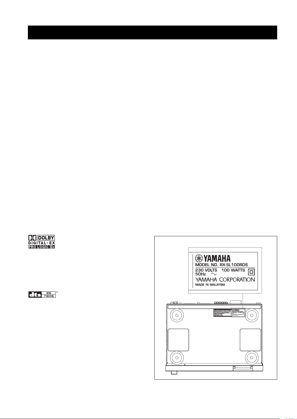
• The following name plate is located on the bottom of this unit.
GETTING STARTED
GETTING STARTED
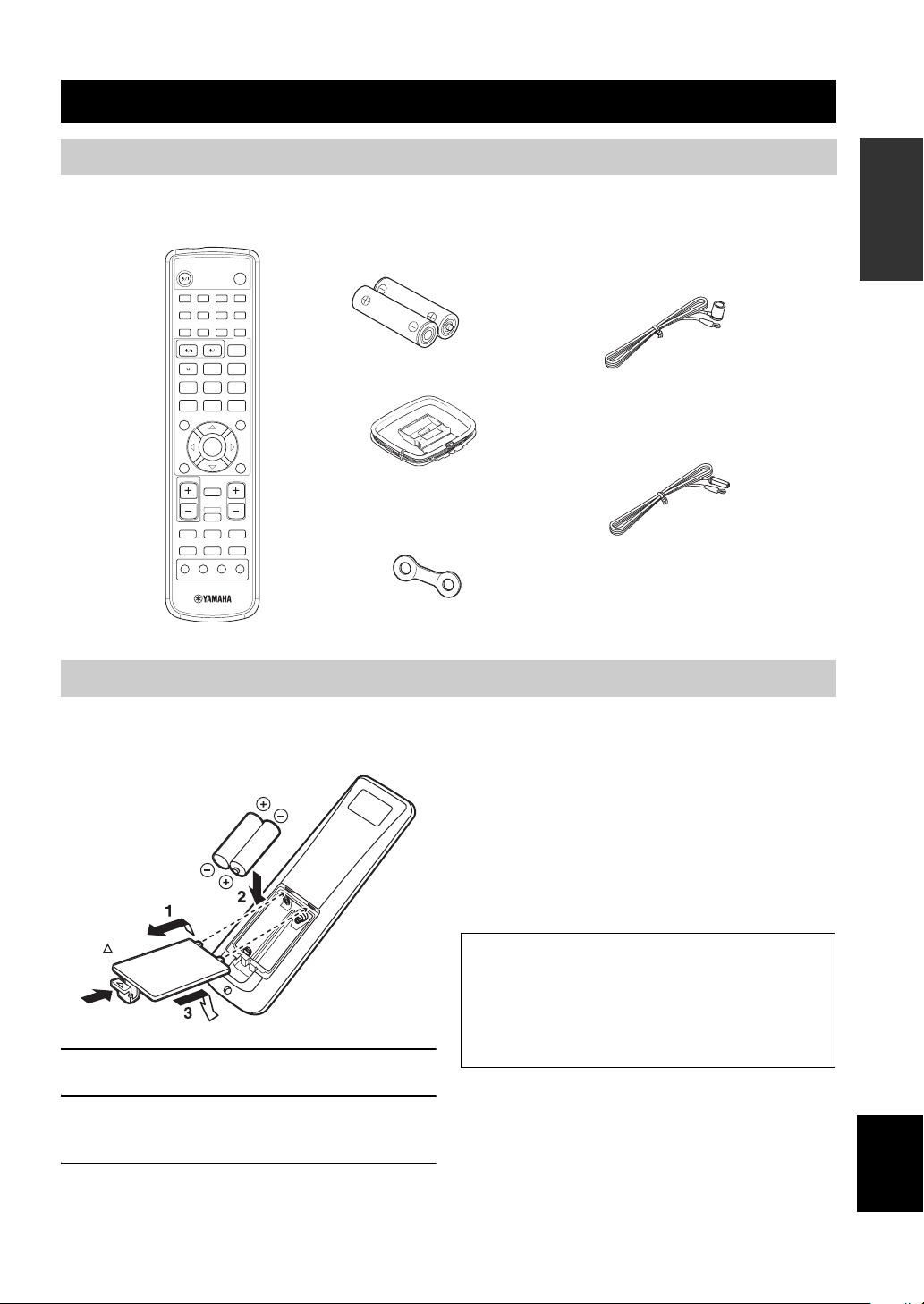
Supplied accessories
Please check that you received all of the following parts.
Remote control
Remote control
STANDBY/ON
HALL2JAZZ3ROCK4ENTERTAIN
MUSIC6TV THTR7MOVIE 18MOVIE 2
q/DTS0NIGHT
DISC SKIP
A/B/C/D/E
TITLE
LEVEL
CH
–
RETURN
TV VOL VOLUME
MUTE INPUT
1
5
9
TV AV
RECsFREQ/RDS
MODE
w
b
ENTER
TEST
MUTE
TUNERDTV/CBL VIDEO 2
TV MODE
EX/ES
+10
CODE SET
AUDIO
PTY SEEK
e
d
PRESET
p
AMP
VCRDVD/CD VIDEO 1
–
CH
RX-SL100RDS
SLEEP
STEREO
EFFECT
EON
START
f
u
a
MENU
SET MENU
DISPLAY
ENT
CH
+
+
Batteries (2)
(AA, R6, UM-3)
AM loop antenna
Cable tags (6 pairs)
INTRODUCTION
Indoor FM antenna
(U.S.A., Canada, Asia and
General models)
(U.K., Europe and
Australia models)
Installing batteries in the remote control
Insert the batteries in the correct direction by aligning the
+ and – marks on the batteries with the polarity markings
(+ and –) inside the battery component.
Check +/–
polarity
Press
1 Remove the back cover.
2 Insert the two supplied batteries (AA, R6,
UM-3) into the battery compartment.
3 Close the back cover.
Notes on batteries
• Change all of the batteries if you notice that the operation range
of the remote control has decreased.
• Do not use old batteries together with new ones.
• Do not use different types of batteries (such as alkaline and
manganese batteries) together. Read the packaging carefully as
these different types of batteries may have the same shape and
color.
• If the batteries have leaked, dispose of them immediately. Avoid
touching the leaked material or letting it come into contact with
clothing, etc. Clean the battery compartment thoroughly before
installing new batteries.
If the remote control is without batteries for more than
3 minutes, or if exhausted batteries remain in the
remote control, the contents of the memory may be
cleared. When the memory is cleared, insert new
batteries, set up the manufacturer code and program
any acquired functions that may have been cleared.
English
3
CONTROLS AND FUNCTIONS
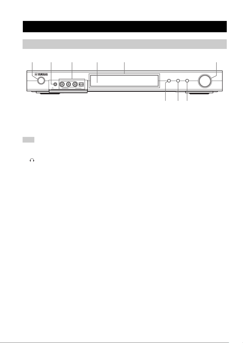
Front panel
CONTROLS AND FUNCTIONS
12 3 5 6
STANDBY
/ON
PHONES VIDEO AUDIO
SILENT
VIDEO 2
OPTICALL R
4
AUTO/MAN’ L
VOLUME/SELECT
INPUT
DSPTUNER
PUSH-ENTER
789
1 STANDBY/ON
Turns on this unit or sets it to the standby mode. When you
turn on this unit, you will hear a click and there will be a 4
to 5-second delay before this unit can reproduce sound.
Note
In standby mode, this unit consumes a small amount of power in
order to receive infrared-signals from the remote control.
2 SILENT (PHONES jack)
Outputs audio signals for private listening with
headphones. When you connect headphones, no signals
are output to the OUTPUT jacks or to the speakers.
All Dolby Digital and DTS audio signals are mixed down
to the left and right headphone channels.
3 VIDEO 2 jacks
Input audio and video signals from a portable external
source such as a game console. To reproduce source
signals from these jacks, select VIDEO 2 as the input
source.
4 Remote control sensor
Receives signals from the remote control.
5 Front panel display
Shows information about the operational status of this
unit.
6 VOLUME/SELECT
Adjusts the volume. Also selects stations, sound field
programs or input sources (etc.) when used together with
TUNER, DSP or INPUT. If no operation is performed
within 5 seconds of pressing TUNER, DSP or INPUT, the
VOLUME/SELECT function automatically returns to
volume.
7 INPUT
Activates the input select mode.
Activates the AM, FM or preset tuning mode when
TUNER is selected as the input source.
8 DSP
Activates the DSP sound field select mode or STEREO
mode.
9 TUNER (AUTO/MAN’L)
Activates the tuning mode when TUNER is selected as the
input source. Press before turning VOLUME/SELECT to
tune in frequencies or preset radio stations.
Switches the AM/FM tuning mode between automatic
(“AUTO” indicator on) and manual (“AUTO” indicator
off) tuning.
4
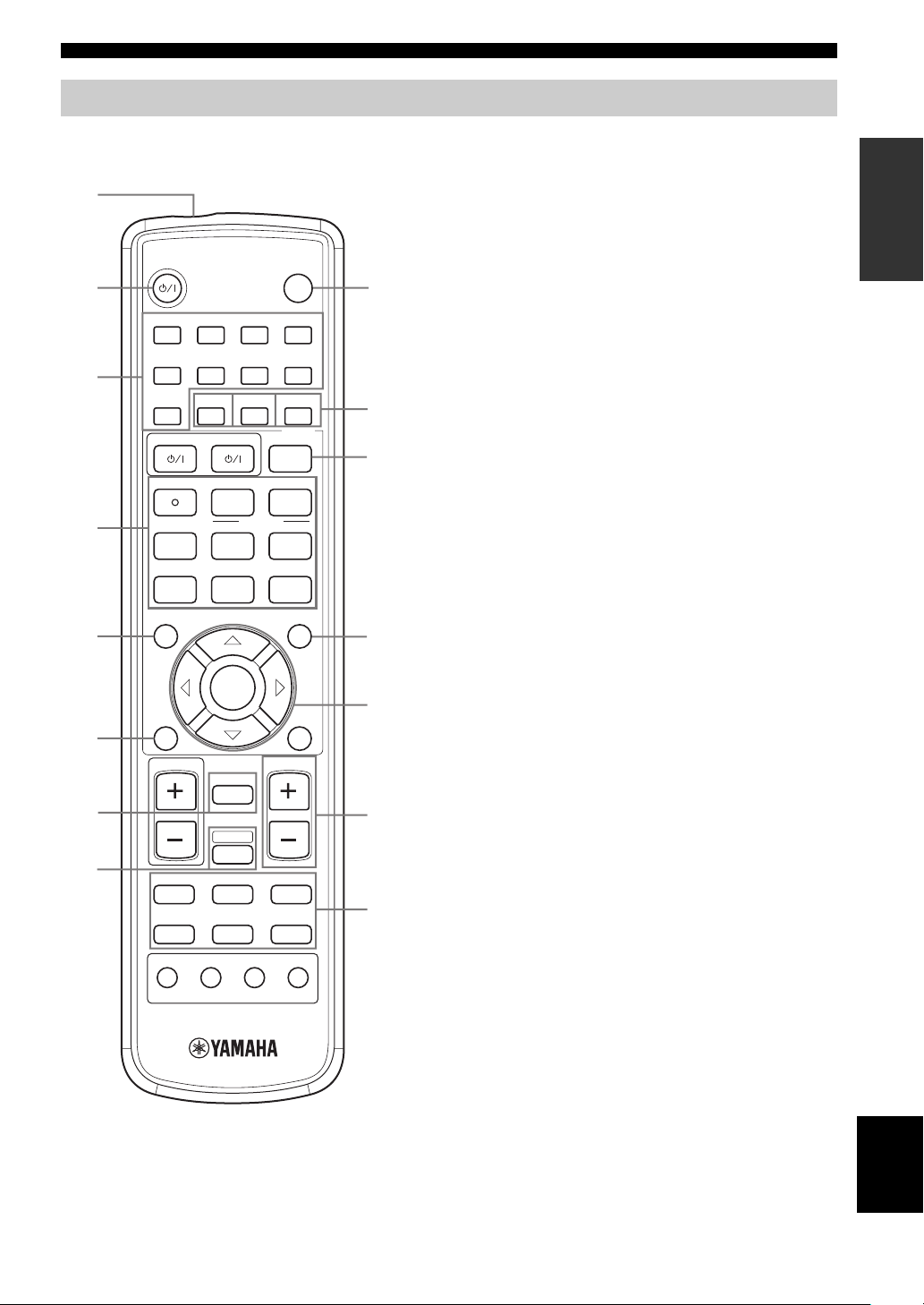
Remote control (AMP mode)
CONTROLS AND FUNCTIONS
Make sure that the AMP mode is selected before starting
operation.
1
2
3
4
5
6
7
8
STANDBY/ON
HALL2JAZZ3ROCK4ENTERTAIN
1
MUSIC6TV THTR7MOVIE 18MOVIE 2
5
q/DTS0NIGHT
9
TV AV
RECsFREQ/RDS
DISC SKIP
A/B/C/D/E
TITLE
LEVEL
CH
RETURN
TV VOL VOLUME
MUTE INPUT
MODE
w
b
–
e
d
p
ENTER
TEST
MUTE
AMP
VCRDVD/CD VIDEO 1
TUNERDTV/CBL VIDEO 2
TV MODE
EX/ES
+10
PTY SEEK
PRESET
–
SLEEP
STEREO
ENT
EFFECT
CODE SET
EON
AUDI O
START
f
u
a
MENU
SET MENU
CH
+
DISPLAY
+
CH
RX-SL100RDS
9
0,A,B
C
D
E
F
G
1 Infrared window
Outputs infrared control signals. Aim this window at the
component you want to operate.
2 STANDBY/ON
Switches the unit on and sets it in the STANDBY mode.
3 DSP program / Numeric buttons
Use to select sound field programs or input numbers
according to the current control area.
4 Operation buttons
Provide functions such as play, stop, skip, etc. for use
when operating other components.
5 LEVEL
Selects the speaker channel to be adjusted and sets the
level.
6 TEST
Outputs the test tone to adjust the speaker levels.
7 MUTE
Mutes the sound. Press again to restore the audio output to
the previous volume level.
8 AMP
Sets the remote control to the AMP mode for controlling
this unit (instead of the component selected using the
input selector buttons).
9 SLEEP
Sets the sleep timer.
0 NIGHT
Turns night listening mode on or off.
A EX/ES
Turns the Dolby Digital EX or DTS-ES decoder on or off.
B STEREO/EFFECT
Switches between normal stereo and DSP effect
reproduction. Select STEREO if you want this unit to
output pure sound from the front left and right speakers.
C CODE SET
Used to set up manufacturer codes.
INTRODUCTION
5
English

CONTROLS AND FUNCTIONS
D SET MENU
Turns the SET MENU on or off.
E Multi control section
Use to select and adjust DSP program parameters or SET
MENU items.
F VOLUME +/–
Increases or decreases the volume level.
G Input selector buttons
Use to select the input source and change the control area.
Using the remote control
VOLUME/SELECT
INPUT
STANDBY
PHONES VIDEO AUDIO
OPTICALL R
/ON
VIDEO 2
SILENT
30 30
STANDBY/ON
SLEEP
HALL2JAZZ3ROCK4ENTERTAIN
1
MUSIC6TV THTR7MOVIE 18MOVIE 2
5
q/DTS0NIGHT
EX/ES
STEREO
9
+10
ENT
EFFECT
TV AV
CODE SET
RECsFREQ/RDS
EON
AUDIO
DISC SKIP
PTY SEEK
MODE
START
w
e
f
u
A/B/C/D/E
d
PRESET
b
p
a
TITLE
MENU
LEVEL
SET MENU
CH
ENTER
–CH+
RETURN
DISPLAY
TEST
TV VOL VOLUME
MUTE
AMP
VCRDVD/CD VIDEO 1
TUNERDTV/CBL VIDEO 2
MUTE INPUT
–
+
CH
TV MODE
RX-SL100RDS
The remote control transmits a directional infrared beam.
Be sure to aim the remote control directly at the remote
control sensor on the main unit during operation.
■ Handling the remote control
• Do not spill water or other liquids on the remote
control.
• Do not drop the remote control.
• Do not leave or store the remote control in the
following types of conditions:
– high humidity such as near a bath
– high temperature such as near a heater or stove
– extremely low temperature
– dusty places
DSPTUNER
AUTO/MAN’L
PUSH-ENTER
Approximately 6 m (20 ft)
6

CONTROLS AND FUNCTIONS
Front panel display
INTRODUCTION
1234 5 678
VCR
MATRIX DISCRETE
ES
DIGITAL
PCM
VIRTUAL
EX
PL
PL
NIGHT
SILENT
HiFi DSP
JI H G E A09BCDF
VIDEO 1 VIDEO 2
DTV/CBL
PS PTY RT CT PTY HOLD EON STEREO TUNED
DVD/CD
TUNER
VOLUME
AUTO MEMORY
ft
mS
LFE
dB
MUTE
SLEEP
L C R
L
SL SB SR
1 Processor indicators
When any of this unit’s decoders function, the respective
indicator lights up.
2 NIGHT indicator
Lights up when you select NIGHT LISTENING mode.
3 Headphones indicator
Lights up when headphones are connected.
4 CINEMA DSP indicator
Lights up when you select a CINEMA DSP sound field
program.
5 Input source indicators
A cursor lights to show the current input source.
6 VOLUME level indicators
Indicate the volume level.
7 MUTE indicator
Flashes while the MUTE function is on.
8 SLEEP indicator
Lights up while the sleep timer is on.
9 MEMORY indicator
Flashes to show a station can be stored in memory.
0 Input channel indicators
Indicates the channel components of the input digital
signal.
A LFE indicator
Lights up when the input signal contains the LFE signal.
B AUTO indicator
Shows that this unit is in the automatic tuning mode.
C TUNED indicator
Lights up when this unit is tuned into a station.
D STEREO indicator
Lights up when this unit is receiving a strong signal for an
FM stereo broadcast while the “AUTO” indicator is lit.
E RDS indicators
(U.K. and Europe models only)
The name(s) of the RDS data offered by the currently
received RDS station light(s) up.
EON lights up when an RDS station that offers the EON
data service is being received.
PTY HOLD lights up while searching for stations in the
PTY SEEK mode.
F HiFi DSP indicator
Lights up when you select a HiFi DSP sound field
program.
G Multi-information display
Shows the current sound field program name and other
information when adjusting or changing settings.
H SILENT indicator
Lights up when headphones are connected and a sound
field program is selected (see page 20).
I VIRTUAL indicator
Lights up when Virtual CINEMA DSP is active (see
page 34).
J PCM indicator
Lights up when this unit is reproducing PCM (pulse code
modulation) digital audio signals.
7
English
SPEAKER SETUP
SPEAKER SETUP
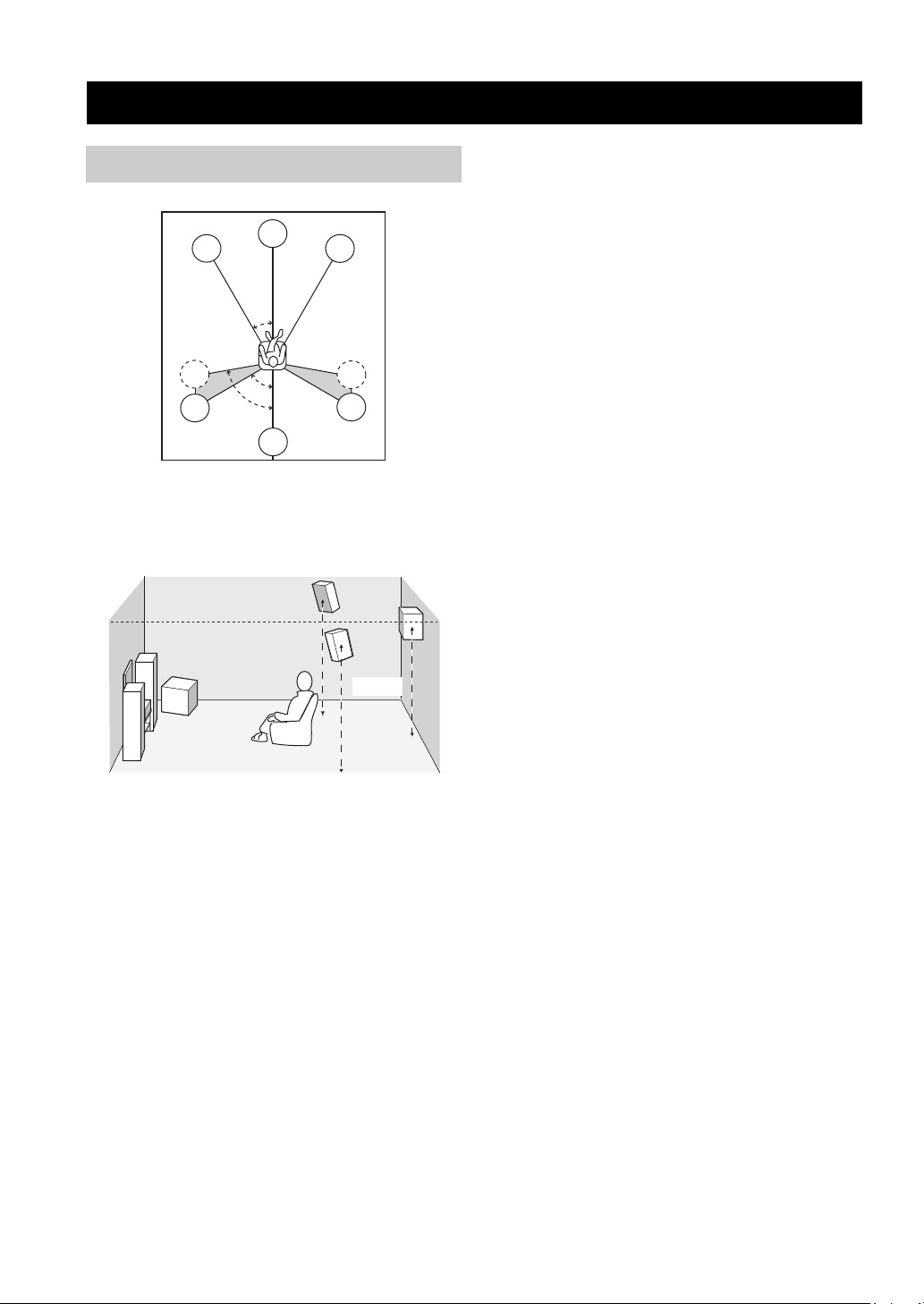
Speaker placement
FL
SL
SL
C
30˚
60˚
80˚
SB
y
The speaker layout above shows the standard ITU-R speaker
setting.
FR
SR
SR
Surround speakers (SR and SL)
The surround speakers are used for effect and surround
sounds. Place these speakers behind your listening
position, facing slightly inwards, about 1.8 m (6 ft) above
the floor.
Surround back speaker (SB)
The surround back speaker supplements the surround
speakers and provide for more realistic front-to-back
transitions. Place this speaker directly behind the listening
position and at the same height as the surround speakers.
Subwoofer
The use of a subwoofer, such as the YAMAHA Active
Servo Processing Subwoofer System, is effective not only
for reinforcing bass frequencies from any or all channels,
but also for high fidelity reproduction of the LFE (lowfrequency effect) channel included in Dolby Digital and
DTS software. The position of the subwoofer is not so
critical, because low bass sounds are not highly
directional. But it is better to place the subwoofer near the
front speakers. Turn it slightly toward the center of the
room to reduce wall reflections.
1.8 m
Front speakers (FR and FL)
The front speakers are used for the main source sound plus
effect sounds. Place these speakers an equal distance from
the ideal listening position. The distance of each speaker
from each side of the video monitor should be the same.
Center speaker (C)
The center speaker is for the center channel sounds
(dialog, vocals, etc.). If for some reason it is not practical
to use a center speaker, you can do without it. Best results,
however, are obtained with the full system. Align the front
face of the center speaker with the front face of your video
monitor. Place the speaker centrally between the front
speakers and as close to the monitor as possible, such as
directly over or under it.
8
SPEAKER SETUP
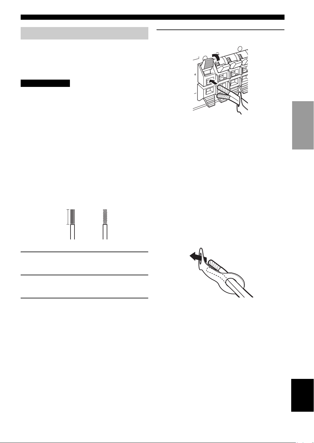
Speaker connections
Be sure to connect the left channel (L), right channel (R),
“+” (colored) and “–” (black) properly. If the connections
are faulty, no sound will be heard from the speakers, and if
the polarity of the speaker connections is incorrect, the
sound will be unnatural and lack bass.
CAUTION
• If you will use 6 ohm speakers, be sure to set this unit’s
speaker impedance setting to 6 ohms before using (see
“IMPEDANCE SELECTOR switch” on page 10).
• Before connecting the speakers, make sure that the
power of this unit is off.
• Do not let the bare speaker wires touch each other or do
not let them touch any metal part of this unit. This
could damage this unit and/or speakers.
• Use magnetically shielded speakers. If this type of
speakers still creates the interference with the monitor,
place the speakers away from the monitor.
A speaker cord is actually a pair of insulated cables
running side by side. One cable is colored or shaped
differently, perhaps with a stripe, groove or ridges.
Connect the striped (grooved, etc.) cable to the “+”
(colored) terminals on this unit and your speaker. Connect
the plain cable to the “–” (black) terminals.
10 mm (3/8″)
1
2
4 Return the tab to secure the wire.
PREPARATION
Colored: positive (+)
Black: negative (–)
■ Cable tags
6 pairs of different colored cable tags are provided with
this product. The colors of the cable tags and their
respective speaker cables are as follows:
• Red: Front right speaker cable
• White: Front left speaker cable
• Green: Center speaker cable
• Gray: Surround right speaker cable
• Blue: Surround left speaker cable
• Brown: Surround back speaker cable
To make it easier to distinguish the various speaker cables,
attach the colored tags to the appropriate speaker cables as
shown below.
1 Remove approximately 10 mm (3/8″) of
insulation from each of the speaker cables.
2 Twist the exposed wires of the cable together
to prevent short circuits.
3 Press and hold the tab to insert the speaker
wire.
English
9
SPEAKER SETUP
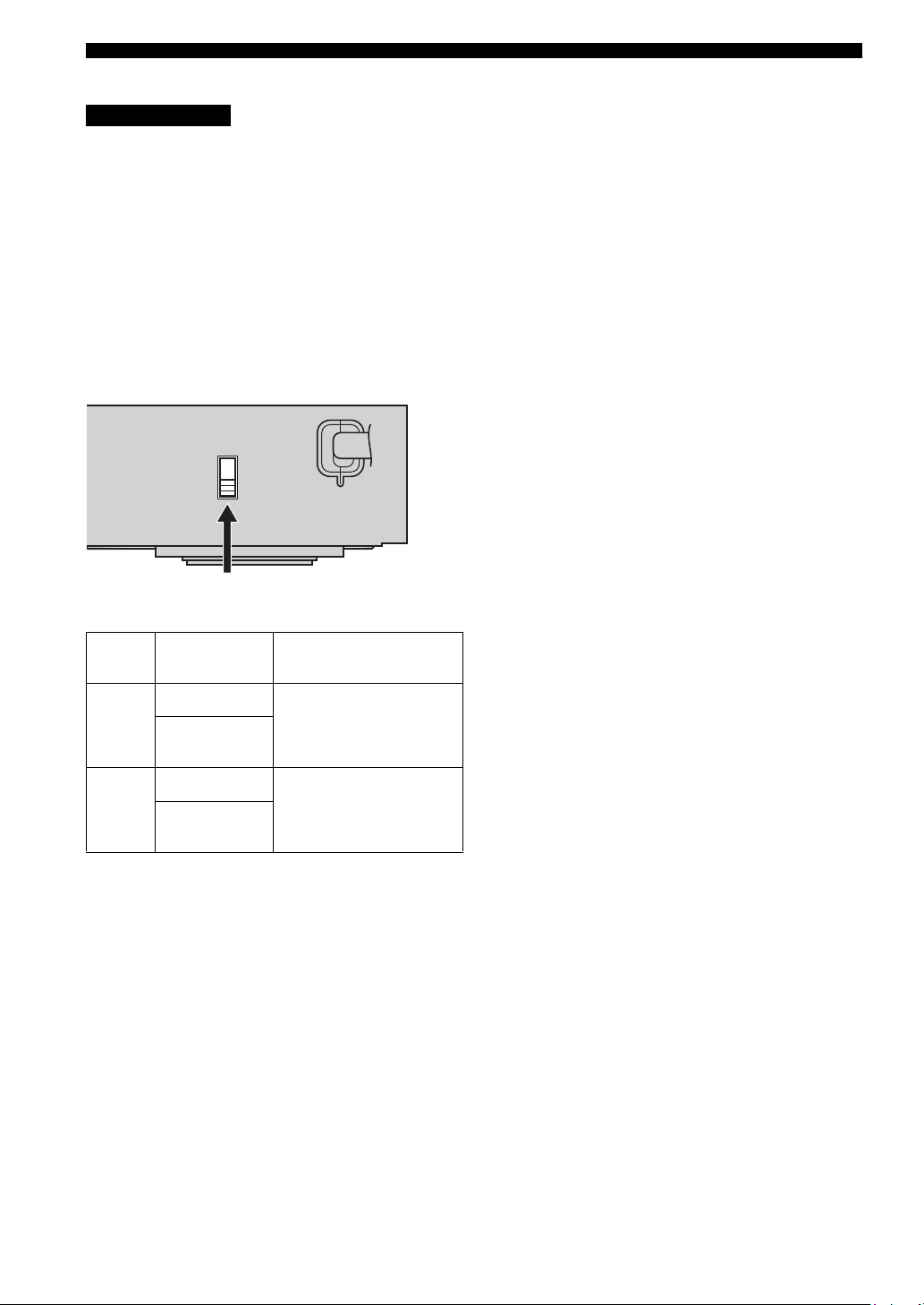
■ IMPEDANCE SELECTOR switch
CAUTION
Do not change the setting of the IMPEDANCE
SELECTOR switch when the unit power is switched on,
as doing so may damage the unit.
If this unit fails to turn on when STANDBY/ON is pressed
on either the front panel or remote control, the
IMPEDANCE SELECTOR switch may not be fully slid to
either position. If this is the case, slide the switch all the
way to either position when this unit is in standby mode.
Be sure to move this switch only when this unit is in
standby mode.
Select the switch position (top or bottom) according to the
impedance of the speakers in your system.
MAINS
IMPEDANCE SELECTOR switch
Switch
position
Top
Bottom
Speaker Impedance level
Front
Center, Surround
back, Surround
Front
Center, Surround
back, Surround
The impedance of each speaker
must be 4 Ω or higher.
The impedance of each speaker
must be 6 Ω or higher.
10
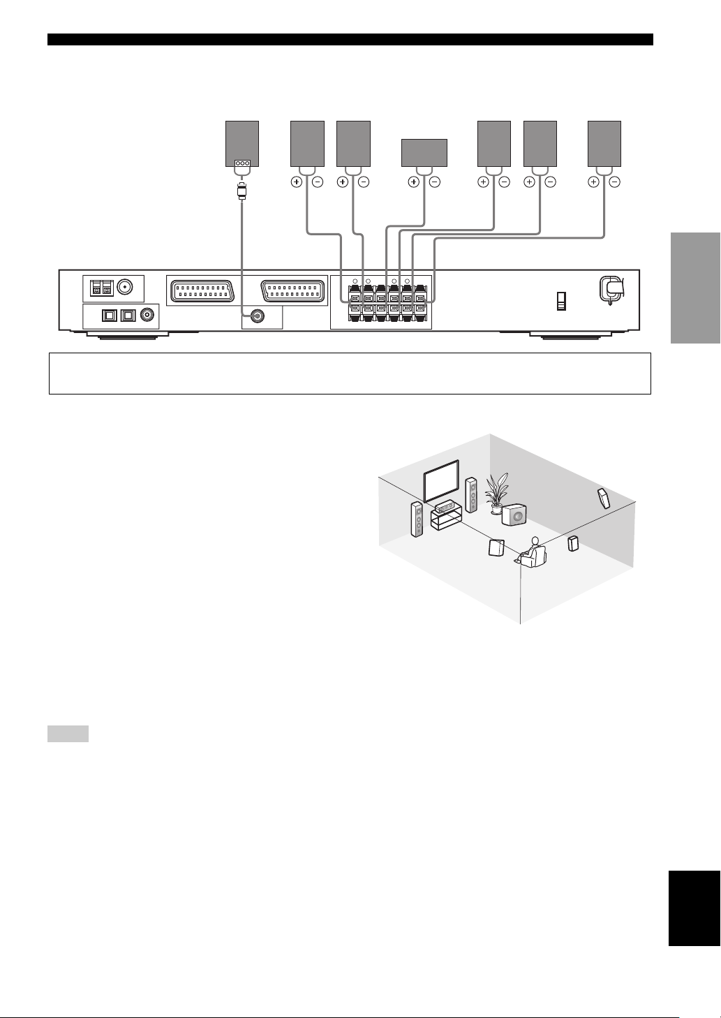
■ Speaker connections
SPEAKER SETUP
Subwoofer
system
Front
speakers
Center
Surround
speakers
Right LeftRight Left
Surround back
speaker
speaker
71 2 4365
PREPARATION
AM ANT FM ANT
GND
TUNER
OPTICAL
DIGITAL
INPUT
DVD
123
/CD
75Ω UNBAL
EXT. IN/OUT
COAXIAL
DTV
VIDEO 1
/CBL
SUBWOOFER
TV IN/OUT
OUTPUT
SPEAKERS
+
–
FRONT
R
L R L
SURR BACKCENTER SURROUND
+
–
• The surround back speaker outputs the surround back channel included in Dolby Digital EX and DTS-ES software and only
operates when the Dolby Digital EX or DTS-ES decoder is turned on.
■ FRONT terminals
Connect your speaker system to these terminals.
■ SURROUND terminals
Connect surround speakers to these terminals.
■ SURROUND BACK terminals
6
2
1
7
3
Connect a surround back speaker to these terminals.
■ CENTER terminals
Connect a center speaker to these terminals.
4
5
■ SUBWOOFER OUTPUT jack
Connect a subwoofer with built-in amplifier, such as the
YAMAHA Active Servo Processing Subwoofer System,
to this jack.
y
You can easily distinguish between the cable pairs by attaching a
supplied cable tag to each end of the respective speaker cable (see
page 9).
Speaker layout
MAINS
Notes
• The cut-off frequency for the SUBWOOFER jack is 90 Hz.
• If you are not using a subwoofer, allocate the signals to the front
left and right speakers by changing the setting item “LFE/Bass
Out” to FRONT on the SOUND menu.
• Use the control on the subwoofer to adjust its volume level. You
can also adjust the volume level using this unit’s remote control
(see page 36).
English
11
CONNECTIONS
CONNECTIONS
Before connecting components
CAUTION
Do not connect this unit or other components to the mains power until all connections between components are complete.
• Make sure that all connections are made correctly — that is to say, L (left) to L, R (right) to R, “+” to “+” and “–”
to “–”. Some components require different connection methods and have different jack names. Refer to the operating
instructions for each component you wish to connect to this unit.
• After you have completed all connections, check them again to make sure they are correct.
• The jack names correspond to the names on the input selector.
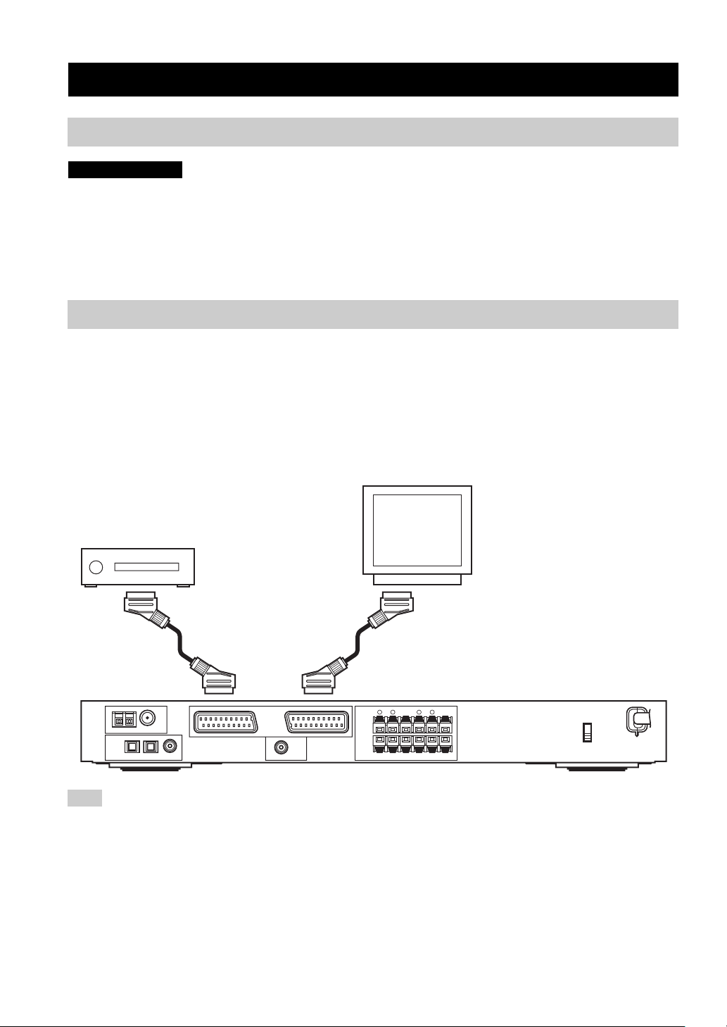
Connecting other components
■ Connecting a TV
Connect one end of the SCART cable to the TV/IN OUT connector on this unit and the other end to the SCART
connector on your TV.
■ Connecting AV components
Connect one end of the SCART cable to the EXT. IN/OUT connector on this unit and the other end to the SCART
connector on your AV component. You can also daisy chain several SCART components together as shown in “Digital
audio connections” (page 13).
AV component
(DVD player, cable tuner, etc.)
AM ANT FM ANT
GND
75Ω UNBAL
TUNER
OPTICAL
DIGITAL
INPUT
COAXIAL
DVD
DTV
123
/CD
/CBL
VIDEO 1
EXT. IN/OUT
SUBWOOFER
OUTPUT
TV IN/OUT
SPEAKERS
+
–
FRONT
R
L R L
TV
SURR BACKCENTER SURROUND
+
–
MAINS
Note
Use a SCART cable to make the above connections. The SCART cable, or “Euro AV cable”, supports IN/OUT signal transmission,
providing you with the best possible picture and sound.
12
CONNECTIONS
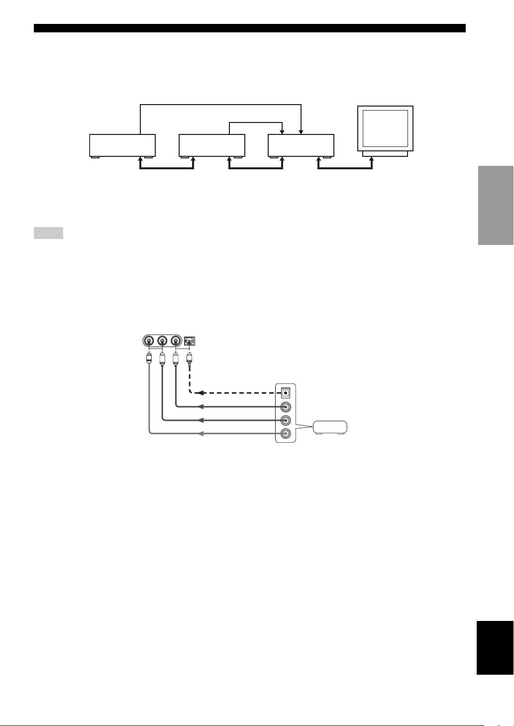
■ Digital audio connections
Connect the optical or coaxial digital output on your components to the corresponding DIGITAL INPUT jacks.
Use OPTICAL 1 (DVD/CD) to connect a DVD or CD player.
Use OPTICAL 2 (DTV/CBL) to connect a DTV or cable tuners.
Optical out
Optical out
DVD player
SCART
DTV or
Cable tuner
SCART
RX-SL100RDS
SCART
y
You can assign components to this unit’s DIGITAL INPUT jacks using the INPUT and VOLUME/SELECT controls on the front panel
(or the input selector buttons on the remote control) (page 43).
Notes
• The OPTICAL jacks on this unit conform to the EIA standard. If you use a fiber optic cable that does not conform to this standard, this
unit may not function properly.
• You may experience some image distortion if your VCR is connected to this unit through your DVD player rather than being directly
connected to this unit.
■ VIDEO 2 jacks (on the front panel)
Use these jacks to connect any video source, such as a game console or video camera, to this unit.
VIDEO AUDIO
V
OPTICALL R
VIDEO 2
O
L
R
Optical out
Audio out R
Audio out L
Game console
or video
camera
Video out
PREPARATION
13
English
CONNECTIONS
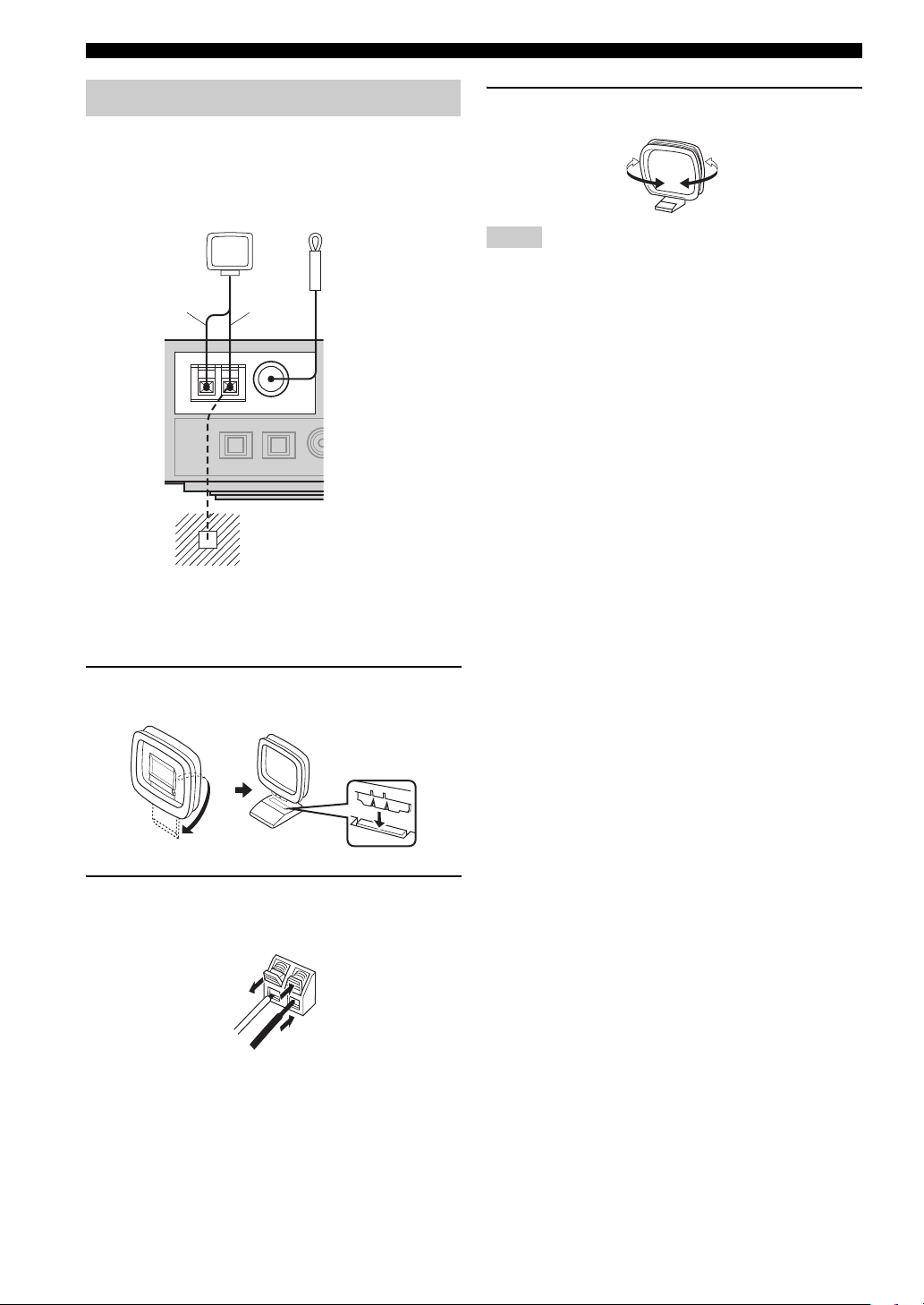
Connecting the antennas
Both AM and FM indoor antennas are included with this
unit. In general, these antennas should provide sufficient
signal strength. Connect each antenna correctly to the
designated terminals.
AM loop antenna
(included)
W h i t e
AM ANT FM ANT
TUNER
Black
GND
75Ω UNBAL
Ground (GND terminal)
For minimum interference, connect the
antenna
ground. A good earth ground is a metal
stake driven into moist earth.
Indoor FM antenna
(included)
GND terminal to a good earth
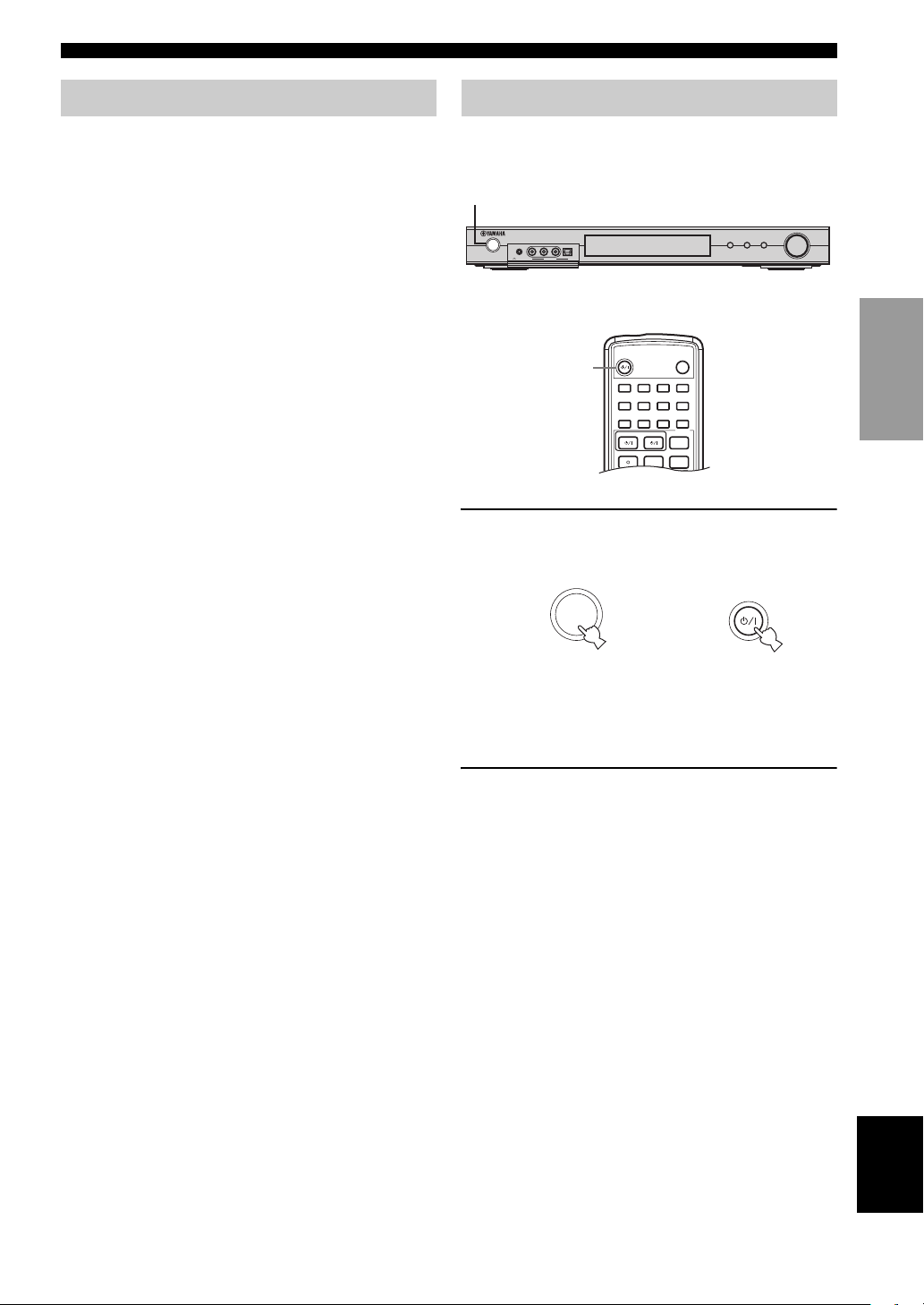
3 Orient the AM loop antenna for the best
reception.
Notes
• The AM loop antenna should be placed away from this unit and
all speaker cords.
• The AM loop antenna should always be connected, even if an
outdoor AM antenna is connected to this unit.
• A properly installed outdoor antenna provides clearer reception
than an indoor one. If you experience poor reception quality, an
outdoor antenna may improve the quality. Consult the nearest
authorized YAMAHA dealer or service center about outdoor
antennas.
■ Frequency Step (Asia and General
models only)
Because the interstation frequency spacing differs in
different areas, set the FREQUENCY STEP (using the onscreen display operations) according to the frequency
spacing in your area (see page 45).
• North, Central and South America: 100 kHz/10 kHz
• Other areas: 50 kHz/9 kHz
■ Connecting the AM loop antenna
1 Set up the AM loop antenna, then connect it
to the terminals on this unit.
2 Press and hold the tab to insert the white
cord into the AM ANT terminal and the black
cord into the GND terminal.
14
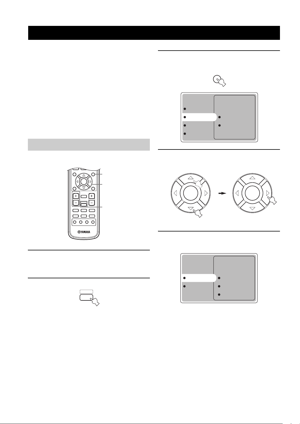
Connecting the power Turning on the power
1
HALL2JAZZ3ROCK4ENTERTAIN
SLEEP
STANDBY/ON
5
MUSIC6TV THTR7MOVIE 18MOVIE 2
9
TV AV
CODE SET
RECsFREQ/RDS
AUDIO
EON
DISC SKIP
MODE
PTY SEEK
START
q/DTS0NIGHT
+10
EX/ES
ENT
STEREO
EFFECT
CONNECTIONS
■ Connecting the AC power
After all other connections are complete, plug the power
cord to an AC wall outlet.
■ Memory back-up
The memory back-up circuit prevents the stored data from
being lost even if this unit is in the standby mode.
However if the power cord is disconnected from the AC
wall outlet, or the power supply is cut for more than one
week, the stored data will be lost.
When all connections are complete, turn on the power of
this unit.
1
VOLUME/SELECT
INPUT
STANDBY
PHONES VIDEO AUDIO
/ON
OPTICALL R
VIDEO 2
SILENT
DSPTUNER
AUTO/MAN’L
PUSH-ENTER
or
1
1 Press STANDBY/ON on the front panel or
remote control to turn on the power of this
unit.
STANDBY
/ON
or
STANDBY/ON
PREPARATION
Front panel
Remote control
The level of the main volume, and then the current
sound field program name appear on the front panel
display.
2 Turn on the video monitor connected to this
unit.
English
15
BASIC SETUP
b
TITLE
LEVEL
ENTER
CH
–
CH
+
p
MUTE
TV VOL VOLU ME
AMP
VCRDVD/CD VIDEO 1
TUNERDTV/CBL VIDEO 2
a
MUTE INPUT
–
CH
TV MODE
+
RX-SL100RDS
MENU
SET MENU
RETURN
TEST
DISPLAY
BASIC SETUP
The BASIC setup feature is a useful way to setup your
system quickly and with minimal effort. The BASIC setup
items are displayed on both the front panel of this unit and
your video monitor. By using the GUI (on your video
monitor), you can easily make any necessary settings.
y
• In addition to using the BASIC menu, you can use the detailed
parameters in the SOUND menu (page 40) to manually
configure this unit using more precise adjustments.
• Altering any parameters in the BASIC menu will reset
parameters in the SOUND menu.
• The explanations in this document are based on the GUI. The
characters shown in the front panel display may differ from
those on the GUI.
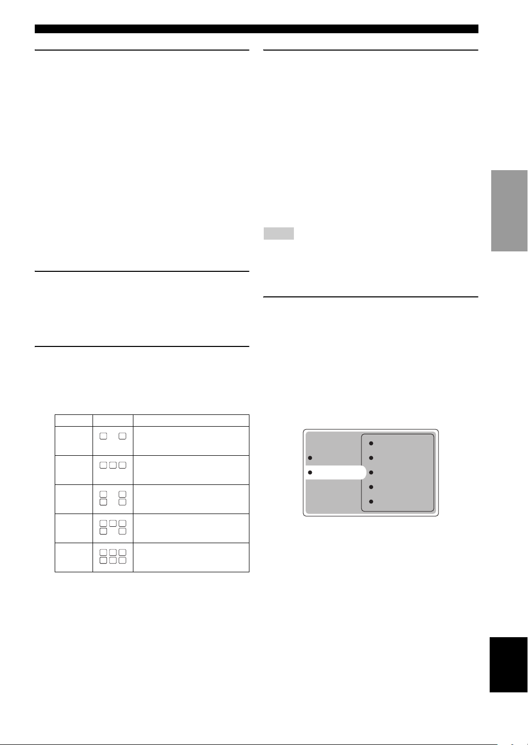
Using BASIC setup
■ Speaker Set Up
3
3 Press SET MENU.
The top display appears on your video monitor.
MENU
SET MENU
OPTION menu
BASIC menu Speaker Set Up
SOUND menu Speaker Level
INPUT menu
4 Press k/n repeatedly to select BASIC menu,
then press h.
4-10
2
1 Switch on the receiver and video monitor.
Make sure the OSD is displayed on your video
monitor.
2 Press AMP.
AMP
16
ENTER
ENTER
5 Press k/n repeatedly to select Speaker Set
Up, then press h.
Speaker Set Up Room Size
Speaker Level Subwoofer Set
Speaker Num
BASIC SETUP
6 Press k/n repeatedly to select Room Size,
then press ENTER.
Use k/n to select the size of the room you have
installed your speakers in, then press ENTER.
Roughly speaking, the room sizes are defined as
follows:
[U.S.A. and Canada models]
S (small) 16 x 13 ft, 200 sq. ft
(4.8 x 4.0 m, 20 m2)
M (medium) 20 x 16 ft, 300 sq. ft
(6.3 x 5.0 m, 30 m
2
)
L (large) 26 x 19 ft, 450 sq. ft
(7.9 x 5.8 m, 45 m
2
)
[Other models]
S (small) 3.6 x 2.8 m, 10 m
M (medium) 4.8 x 4.0 m, 20 m
L (large) 6.3 x 5.0 m, 30 m
2
2
2
7 Press k/n repeatedly to select Subwoofer
Set, then press ENTER.
Use k/n to select Yes or None, then press ENTER.
Yes If you have a subwoofer in your system.
None If you do not have a subwoofer in your system.
8 Press k/n repeatedly to select Speaker Num,
then press ENTER.
Use k/n to select the number of speakers connected
to the unit, then press ENTER. The choices vary as
follows:
Choices Display Speakers
2 spk
3 spk
4 spk
5 spk
6 spk
LL C R
SL SB SR
LL CR
SL SB SR
LL C R
SL SB SR
LL C R
SL SBSBSR
LL C R
SL SB SR
Front L/R
Front L/R, Center
Front L/R, Surround L/R
Front L/R, Center, Surround L/R
Front L/R, Center, Surround L/R,
Surround back
9 After you have finished the settings, press n
repeatedly to select Setting OK?, then press
ENTER.
Use k/n to select Set or Cancel, then press ENTER.
Set To apply the changes and start the test
tone.
Cancel To cancel the changes and return to
Speaker Set Up.
Use the test tone to check the speaker levels.
If you selected Set, the display changes to “CHECK:
Test Tone”, and the unit outputs a test tone from each
speaker in turn. When the test tone begins, the display
changes to “CHECK OK: YES”.
Notes
• The unit cycles the test tone around each of the speakers in turn
twice.
• The indicator of the speaker currently outputting the test tone
flashes on the front panel display.
10 Press k/n repeatedly to select Yes or No,
then press ENTER.
Yes To return to Speaker Set Up.
No To enter Speaker Level.
■ Speaker Level
Use this menu to compare and adjust the test tone output
from each speaker to the output from the left front (or left
surround) speaker so that the volume level for all speakers
is identical.
Front
Speaker Set Up Center
Speaker Level Sur L
Sur R
Sur Back
Press ENTER to enter the Speaker Level
adjustment menu, then press k/n to select a
speaker and adjust the balance using l / h.
The unit outputs the test tone from the selected speaker
and the left front (or left surround) speaker in turn. The
indicator of the speaker currently outputting the test tone
flashes on the front panel display.
PREPARATION
17
English
Loading…
-
Страница 1
YAMAHA ELECTRONICS CORPORATION, USA 6660 ORANGETHO RPE AVE., BUEN A PARK, CALIF. 90620, U.S.A. YAMAHA CANADA MUSIC LTD. 135 MILNER AVE., SCAR BOROUGH, ONTARIO M1S 3R1, CAN ADA YAMAHA ELECTRONIK EUROPA G.m.b.H. SIEMENSSTR. 22-34, 25462 RE LLINGEN BEI HAMBURG , F.R. OF GERMANY YAMAHA ELECTRONIQUE FRANCE S.A. RUE AMBROISE CROIZA T BP70 CROISSY-BEAUB O[…]
-
Страница 2
CAUTION: READ THIS BEFO RE OPERATING YOUR UNIT. 1 T o assure the finest performance, please read this manual carefully . Keep it in a safe place f or future reference. 2 Install this sound system in a well ventilated, co ol, dry , clean place — away fr o m direct sunlight, heat sources, vibration, dust, moisture , and/or cold. Allow ventilation s[…]
-
Страница 3
1 English PREP ARA TION INTRODUCTION BAS I C OPERA TION SOUND FIELD PROGRAM S AD V ANCED OPERA TION ADDITIONAL INFORMA TION FEATU RES …. ……… ………… ………. ………… ………. …. 2 GETTING STARTED … ………. ………… ………… ……. 3 Supplied accessories ………….. ……………. ………… …….. 3 In[…]
-
Страница 4
FEATURES 2 Built-in 6-channel original Y amaha digi tal power amplifier ◆ Minimum RMS output po wer (0.9% THD, 1 kHz, 6 Ω ) Front: 70 W + 70 W Center: 70 W Surround: 70 W + 70 W Surround Back: 70 W ◆ (10% THD, 1 kHz, 4 Ω ) Front: 75 W + 75 W Center: 75 W Surround: 75 W + 75 W Surround Back: 75 W Sound field features ◆ Proprietary Y AMAHA […]
-
Страница 5
GETTING STARTED 3 English INTRODUCTION Please check t hat you recei ved all of the following parts. Insert the batteri es in the correct direction b y aligning the + and – marks on the batteries with the polarity markings (+ and –) inside the battery component. 1 Remove the back co ver. 2 Insert the two supplied batteries (AA, R6, UM-3) into th[…]
-
Страница 6
CONTROLS AND FUNCTIONS 4 1 ST ANDBY/ON T urns on this unit or sets it to the standby mode. When you turn on this unit, you will hear a click and ther e will be a 4 to 5-second delay before this unit can reproduce sound. In standby mo de, this unit consumes a small amount of power in order to receive infrared-signa ls from the remote control. 2 SILE[…]
-
Страница 7
CONTROLS AND FUNCTIONS 5 English INTRODUCTION Make sure that the AMP mode is selected before starting operation. 1 Infrared windo w Outputs infrared control signa ls. Aim this windo w at the component you want to operate. 2 ST ANDBY/ON Switches the unit on and sets it in the ST ANDBY mode. 3 DSP program / Numeric buttons Use to select sound f ield […]
-
Страница 8
CONTROLS AND FUNCTIONS 6 D SET MENU T urns the SET MENU on or off. E Multi control section Use to select and adjust DS P program parameters or SET MENU items. F VO L U M E + / – Increases or decre ases the v olume le vel. G Input selector buttons Use to select the i nput source and change the control area. The remote control transmits a direction[…]
-
Страница 9
CONTROLS AND FUNCTIONS 7 English INTRODUCTION 1 Processor indicators When any of this u nit’ s decode rs function, the respecti ve indicator lights up. 2 NIGHT indica tor Lights up when you select NIGHT LISTENING mode. 3 Headphones indicator Lights up when headphones are connected. 4 CINEMA DSP indicator Lights up when you select a CINEMA DSP sou[…]
-
Страница 10
SPEAKER SETUP 8 y The speaker layout above sho w s the standard ITU-R speaker setting. Fr ont speaker s (FR and FL) The front speakers are used fo r the main source sound plus effect sounds. Place these spea kers an equal distance from the ideal listeni ng position. The distanc e of each speaker from each side of the video monitor should be the sam[…]
-
Страница 11
9 English SPEAKER SE TUP PREP ARA TION Be sure to connect the lef t channel (L), right channel (R), “+” (colored) and “–” (black) properly . If the connections are faulty , no sound will be hear d from the speakers, and if the polarity of the speak er connections is incorrect, the sound will be unnatu ral and lack bass. • If you will us[…]
-
Страница 12
10 SPEAKER SETUP ■ IMPED A NCE SELECT O R switc h Do not change the setting of the IMPED ANCE SELECTOR switch when the unit power is switched on, as doing so may damage the unit. If this unit fails to turn on when ST ANDBY/ON is pressed on either the front panel or remote control, the IMPED ANCE SELECTOR switch may not be fully slid to either pos[…]
-
Страница 13
11 English SPEAKER SE TUP PREP ARA TION ■ Speaker connect ions ■ FRONT terminals Connect your speaker system to these terminals. ■ SURROUND terminals Connect surround speak ers to these terminals. ■ SURROUND B A CK terminals Connect a surround back speaker to these terminals. ■ CENTER terminals Connect a center speak er to these terminals[…]
-
Страница 14
CONNECTIONS 12 Do not connect this unit or other com ponents to the mains po wer unt il all connections betwee n components are complete. • Make sure that all connections are made correctly — that is to say , L (left) to L, R (right) to R, “+” to “+” and “–” to “–”. Some components require dif fer ent connection methods and ha[…]
-
Страница 15
13 English CONNECTIONS PREP ARA TION ■ Digital audio connections Connect the optical or coaxial digital output on your components to the corresponding DIGIT AL INPUT jacks. Use OPTICAL 1 (D VD/CD) to connect a DVD or CD p layer . Use OPTICAL 2 (DTV/CBL) to connect a DTV or cable tuners. y Y ou can assign components to this unit’ s DIGIT AL IN P[…]
-
Страница 16
14 CONNECTIONS Both AM and FM indoor antennas are included with this unit. In general, these ante nnas should pr ovide suf ficient signal strength. Connect ea ch antenna correctly to the designated terminals. ■ Connecting the AM loop ant enna 1 Set up the AM loop ante nna, then connect it to the terminals on this unit. 2 Press and hold the tab to[…]
-
Страница 17
15 English CONNECTIONS PREP ARA TION ■ Connecting the A C power After all other conne ctions are complete, plug the power cord to an A C wall outlet. ■ Memory back-u p The memory back-up circuit pre vents the stored data from being lost ev en if this uni t is in the standby mode. Howe ver if the po wer cord is disconnected from the A C wall out[…]
-
Страница 18
BASIC SETUP 16 The BASIC setup feature is a useful way to setup your system quickly and with minimal ef fort. The B ASIC setup items are displayed on both the front panel of this unit and your video monitor . By using the GUI (on your video monitor), you can easily make any necessary settings. y • In addition to using the B A SIC menu, you can us[…]
-
Страница 19
17 English BASIC SETUP PREP ARA TION 6 Press k / n repeatedly to select Room Size, then press ENTER. Use k / n to select the size of the room you have installed your speakers in, then press ENTER. Roughly speaking, the room sizes are defined as follows: [U.S.A. and Canada models] S (small) 16 x 13 ft, 200 sq. ft (4.8 x 4.0 m, 20 m 2 ) M (medium) 20[…]
-
Страница 20
18 BASIC SETUP Front Adjusts the balance betwee n the front left and right speakers. Center Adjusts the balance between the front left and center spea kers. Sur L Adjusts the balance betw een the front left and surround left speakers. Sur R Adjusts the balance betw een the surround left and surround right speak ers. Sur Back Adjusts the balance bet[…]
-
Страница 21
PLAYBACK 19 English BAS I C OPERA TION 1 Press ST ANDBY/ON to turn on the power . 2 T urn on the video mon i tor connected to this unit. 3 Press INPUT, then r o tate V OLUME/SELECT within 5 seconds to se lect the input source (or press an input selector button on the remote control). The current input source name and input mode appear in the front […]
-
Страница 22
20 PLAYBACK T o listen with head phones (SILENT CINEMA) The SILENT CINEMA mode al lo ws you to enjoy multi- channel music or movie soun d, including Dolby Digital and DTS surround, through ordinary headphones. SILENT CINEMA activ a tes automatically whenev er you connect headphones to the P HONES jack while listening to CINEMA DSP or HiFi D SP soun[…]
-
Страница 23
21 English PLAYBACK BAS I C OPERA TION ■ Front panel operatio n Press DSP , then r otate V OLUME/SELECT within 5 seconds. The name of the selected program appears o n the front panel display . y Choose a sound f ield program based on yo ur listening preference, and not on the name of the progr am. • If no oper ation is perfo rmed w ithin 5 seco[…]
-
Страница 24
TUNING 22 There are 2 tuning methods ; automatic and manual. Automatic tuning is ef fectiv e when station signals are strong and there is no interference. ■ A utomatic tuni ng 1 Press INPUT, then rotate V OLUME/SELECT within 5 seconds to select TUNER. If no operation is pe rformed within 5 seco nds of pressing INPUT on the front panel, the functi[…]
-
Страница 25
23 English TUNING BAS I C OPERA TION ■ Manual tuning If the signal from the station you want to select is weak, you must tune into it manually . 1 Press INPUT, then rotate V OLUME/SELECT within 5 seconds to select TUNER. If no operation is per formed within 5 seconds of pressing I NPUT on the front pa nel, the func tion of VOLUME/SELECT switches […]
-
Страница 26
24 TUNING ■ A utomaticall y presetting FM stations Y ou can use the automatic pres et tuning feature to store FM stations. This function enables this un it to automatically tune in to FM stations with strong signals, and to store up to 40 (8 stations x 5 groups) of those stations in order . Y ou can th en recall any preset station easily by selec[…]
-
Страница 27
25 English TUNING BAS I C OPERA TION ■ Manuall y presetting stations Y ou can also store up to 40 stat ions (8 stations x 5 groups) manually . 1 T une into a station. See page 22 for tuning instructions. When tuned into a station, the front panel display shows the frequency of the station recei ved. 2 Hold down V OL UME/SELECT for appro ximately […]
-
Страница 28
26 TUNING ■ Front pa nel operation 1 Press INPUT, then rotate V OLUME/SELECT within 5 seconds to select TUNER. 2 Press INPUT repeatedly to select preset tuning mode. A colon (:) appears on the front p anel display in front of the station band and frequenc y . 3 Press TUNER (A UTO/MAN’L). The “TUNER” indicator flashes for about 5 seconds, a […]
-
Страница 29
27 English TUNING BAS I C OPERA TION The four modes are av ailable in this unit for displaying RDS data. The PS, PTY, R T a nd/or CT mode indicators that correspond to the RDS da ta services offered by the station light up on the front panel display . Press FREQ/ RDS on the remote repe atedly to change the display mode among the RDS data of fered b[…]
-
Страница 30
28 TUNING This function uses the E ON data service on the RDS station network. If you select the desired program type (NEWS, INFO, AFF AIRS or SPOR T), this unit automatically searches for all preset RDS st ations that are scheduled to broadcast the se lected type of program and switches from the station currentl y being recei ved to the new statio[…]
-
Страница 31
RECORDING 29 English BAS I C OPERA TION When Standby SCAR T is set to “ON”, signals can pass through this unit’ s SCAR T connect ors ev en if this unit is in the standby mode. T his a llows you to record between the connected exte rnal comp onents. If you experience dif ficulties recording through this unit’ s SCAR T connectors, do the foll[…]
-
Страница 32
SOUND FIELD PROGRAM DESCRIPTIONS 30 This unit is equipped with a variety of precise d igital de coders that allow you to enjo y multi-channel playback from almost any sound source (stereo or multi-channel). This unit is also e quipped with a Y AMAHA digital sound field processing (DSP) chip containing sev eral sound field programs which you can use[…]
-
Страница 33
31 English SOUND FIELD PROGRAM DESCRIPTIONS SOUND FIELD PROGRAM S Y ou can select from the follo wing sound f i elds when playing movie or video source s, like D VD, digita l TV, video tapes, etc. For CINEMA-DSP programs Source type Remote butt o n Program Sub program Features For audi o- video sources ENTER T AINME NT Game CINEMA DSP pro cessing. […]
-
Страница 34
ADVANCED OPERATIONS 32 Use this feature to automa tically set this unit in th e standby mode after a certain amount of time. The sleep timer is useful when you are goi ng to sleep while this unit is playing or recording a source. ■ Setting the sleep time r 1 Select a source and start playbac k on the sour ce compo nent. 2 Press SLEEP repeatedly o[…]
-
Страница 35
33 English ADVANCED OPERATIONS AD V ANCED OPERA TION • Some 6.1-channel compatible discs do not ha v e a signal (flag) which this unit can automatically detect. When playing these kinds of discs with 6.1-channel, select “ON”. • 6.1-channel playback is n ot possible ev en if EX/ES is pressed in the following cases: – When Surround Back is […]
-
Страница 36
34 ADVANCED OPERATIONS V irtual CINEMA DSP allows you to enjoy the CINEMA DSP programs without surround speak ers. It creates virtual speakers to reproduc e the natural sound fi eld. If you do not connect surround speakers, V irtual CINEMA DSP activ ates auto matically whenev er you select a CINEMA DSP sound field program. V irtual CINEMA DSP w ill[…]
-
Страница 37
35 English ADVANCED OPERATIONS AD V ANCED OPERA TION 6 Press k / n repeatedly to se lect the desired input mode, then press ENTER. Analog Selects only analog signals. If no analog signals are input, no sound is output. Auto Automatical ly selects input si gnals in the follow ing order: 1) Digital signals* 2) Analog signals dts Selects only digita l[…]
-
Страница 38
36 ADVANCED OPERATIONS ■ Displa ying inf ormation about t he input sour ce Y ou can display the ty pe, format and sampling frequenc y of the current input signal. 1 Press AMP. 2 Press STEREO/EFFECT so that “STEREO” appear s in the displa y . 3 Press k / n to display the f ollowing information about the input signal. (Format) Signal format dis[…]
-
Страница 39
37 English ADVANCED OPERATIONS AD V ANCED OPERA TION Y ou can use the test tone fe ature to manually balance your speaker lev e ls. Please note tha t this operation will ov erride the le vel adju stments made in the Spe aker Le vel section of B ASIC setup (page 17). Use the test tone to set speaker le vels so that the v olume from each speaker is i[…]
-
Страница 40
SET MENU 38 Y ou can use the follow ing parameters to adjust a variety of system settings and customiz e the way this unit operates. Change the initial settings (i ndicated in bold under each parameter) to refl ect the needs of your listening en vironment. ■ BAS I C m e n u Use to quickly setup basic syst em parameters (see page 16). ■ SOUND me[…]
-
Страница 41
39 English SET MENU AD V ANCED OPERA TION Y ou can enjo y good quality sound with the factory-set parameters. Although you do not ha ve to change the initial settings, you can change some of the parameters to better suit the input source or your listening room. Use the remote control to acce ss and adjust each parameter . 1 Press AMP, then press SE[…]
-
Страница 42
40 SET MENU Use this menu to manually ad just any speaker setting. 1 Press AMP to select the AMP mode, then press SET MENU. 2 Press k / n repeatedly to select SOUND menu, then press h . 3 Select the desired parameters, then press ENTER to access and adjust. ■ Center SP . GEQ (Center speaker graphi c equalizer) Use this feature to switch between t[…]
-
Страница 43
41 English SET MENU AD V ANCED OPERA TION ■ Speaker Set (Speaker se t) Use to manually adjust an y speaker sett ing. SOUND menu > Speaker Set > Center (Center speaker) Choices: Lar ge (large ), Small (small), None (none) • Select Large if you ha v e a large center speaker . The unit directs the entire range of the center channel signal to[…]
-
Страница 44
42 SET MENU ■ SP Distanc e (Speaker dist ance) Use this feature to manually input the distance of each speaker and adjust the delay a pplied to respec ti ve ch annel. Ideally , each speaker should be the same distance from the main listening position. Howe ve r , this is not possible in most home situati ons. Thus, a certain amount o f delay must[…]
-
Страница 45
43 English SET MENU AD V ANCED OPERA TION Use this menu to manually adjust any input setting. 1 Press AMP to select the AMP mode, then press SET MENU. 2 Press k / n repeatedly to se lect INPUT menu, then press h . 3 Select the desired parameters, then press ENTER to access and adjust. ■ Input Assign (In put assignment) Y ou can assign ho w this u[…]
-
Страница 46
44 SET MENU ■ Input Mode (Input mode) Use this feature to designate the input mode for sources connected to the DIGIT AL INPUT jacks when you turn on this unit (see page 19 for details abo ut the input mode). INPUT menu > Input Mode > SETTING Choices: Fixed , V ariable(Last), V ariable(Auto) • Select Fixed to fi x the input mode used for […]
-
Страница 47
45 English SET MENU AD V ANCED OPERA TION ■ Display Dimmer (Displa y dimmer) OPTION menu > Display Dimmer > DIMMER (Dimmer) Use to adjust the brightness of the front panel display . Choices: –4 to 0 ■ Memory Guard (Memory guar d) Use this feature to pre vent accidental changes to DSP program parameter values a nd other system settings. […]
-
Страница 48
REMOTE CONTROL FEATURES 46 In addition to controlling this unit, th e remote control can operate other A/ V components made by Y AMAHA and other manufacturers. T o control other compone nts, set up the remote control with the appropriate manufacturer codes. ■ Controlling this unit The shaded a reas belo w can be used to control this unit when the[…]
-
Страница 49
47 English REMOTE CONTROL FEATURES AD V ANCED OPERA TION Once you set the appropriate manufacturer codes, you can use this remote to control your other components. Note that some b uttons may not correctly operate the selected component. Use the input sele ctor buttons to select the component you want to operate. The remote control automatically sw[…]
-
Страница 50
48 REMOTE CONTROL FEATURES Y ou can operate other components if you hav e set the manufacturer code for your component in the remote control. Please note that some buttons may not operate th e component as expected. When you select an input source, the remote control a utomatically swi tches to the mode for operating that component. *1 This button […]
-
Страница 51
EDITING SOUND FIELD PARAMETERS 49 English ADDITIONAL INFORMA TION What really cre ates the rich, full tones of a li ve instrument are the multiple refl ections from the wa lls of the room. In addition to making the sound “live”, these reflections enable us to t ell where the p layer is situated, and the size and shape of the room in wh ich we a[…]
-
Страница 52
50 EDITING SOUND FIELD PARAMETERS 3 Press k / n repeatedly to access the sound field program parameter s. 4 Press l / h repeatedly to adjust the sound field parameter . 5 T o change parameter values f or a different sound field, repeat steps 2 through 4. Y ou cannot change parameter v alues when Memory Guard is set to “ON”. If you want to chang[…]
-
Страница 53
TROUBLESHOOTING 51 English ADDITIONAL INFORMA TION Refer to the chart belo w when this unit does not function prope rly . If the problem you are experiencing is no t listed belo w or if the instruction below does not help, set this unit to the standby mode, unplug the power cor d from the outlet, and contact the nearest authorized Y A MAHA dealer o[…]
-
Страница 54
52 TROUBLESHOOTING Problem Cause Remedy Ref er to page The sound suddenly goes off. The protec tion circu it has been ac tiv ated because of a short cir cuit, etc. Check th at the impe dance selec tor setti ng is correct . 10 Check the s peaker wires a re not tou ching each o ther and then t urn this u nit back on. — The sleep ti mer has tur ned […]
-
Страница 55
53 English TROUBLESHOOTING ADDITIONAL INFORMA TION Prob lem Cause Remedy Refer to page Dolby Digital or DTS sources cannot be played. (Dolb y Digital or DTS indicator on the front panel display does not light up.) The conne cted compon ent is not set to output Dolby Digital or DTS digital signals. Make an appropr iate sett ing following th e operat[…]
-
Страница 56
54 TROUBLESHOOTING ■ T uner Problem Cause Remedy Refer to page FM FM stereo recep tion is noisy . The charact eristics o f FM stereo broadcasts may cause th is problem when the transmi tter is too f ar aw ay or the antenn a input is poor . Check th e antenna co nnection s. Try using a high-qua lity dire ctional FM antenna. 14 Use the man ual tuni[…]
-
Страница 57
55 English TROUBLESHOOTING ADDITIONAL INFORMA TION ■ Remote contr ol Prob lem Cause Remedy Refer to page The remote con trol does not work or function properly . Wrong distan ce or angle. The remote control will function wit hin a maximum range of 6 m (20 ft) an d no more tha n 30 degrees off- axis from the front panel. 6 Direct sunl ight or lig […]
-
Страница 58
GLOSSARY 56 ■ Dolb y Surr ound Dolby Surround uses a 4 channel analog reco rding system to reproduce realistic and dyn amic sound ef fects: 2 front left and right channe ls (stere o), a center channel for dialog (monaural), and a surround channel for special sound effects (monau ral). The surround channel reproduces sound within a narro w frequen[…]
-
Страница 59
57 English GLOSSARY ADDITIONAL INFORMA TION ■ CINEMA DSP Since the Dolby Surround and DTS systems were originally designed for use in mo vie theaters, their ef fect is best felt in a theat er ha ving man y speakers and designed for acoustic ef fects. Since home conditions, such as room size, wall material, number of speakers, and so on, can dif f[…]
-
Страница 60
SPECIFICATIONS 58 A UDIO SECTI ON • Mi nimum RMS Ou tput Power for Front, C enter, Surround, Surround ba ck [U.S.A and C anada models ] 1 kHz, 0.9% THD, 6 Ω ……………… ………… 65 W + 65 W (FTC) [U.K. and Euro pe models] 1 kHz, 0.9% THD, 6 Ω ……………… ………………….. 70 W + 7 0 W 1 kHz, 10% THD, 4 Ω …………[…]
-
Страница 61
LIST OF MANUF A CTURER CODES LISTE DES CODES D E F ABRICANT LISTE DER HERSTELLERCODES LIST A ÖV ER TILL VERKARKODER LIST A DEI CO DICI DEI F ABBRICANTI LIST A DE CÓDIGOS DE F ABRICANTES LIJST MET F A BRIKANTENCODES TV Y AMAHA 299, 292 ADMIRAL 292, 293 AIW A 294, 276, 283, 284 AKAI 295, 296 ALBA 296 A OC 297 BELL&HOWELL 292 BEST AR 298 BLA UPU[…]
-
Страница 62
YAMAHA ELECTRONICS CORPORATION, USA 6660 ORANGETHO RPE AVE., BUEN A PARK, CALIF. 90620, U.S.A. YAMAHA CANADA MUSIC LTD. 135 MILNER AVE., SCAR BOROUGH, ONTARIO M1S 3R1, CAN ADA YAMAHA ELECTRONIK EUROPA G.m.b.H. SIEMENSSTR. 22-34, 25462 RE LLINGEN BEI HAMBURG , F.R. OF GERMANY YAMAHA ELECTRONIQUE FRANCE S.A. RUE AMBROISE CROIZA T BP70 CROISSY-BEAUB O[…]
- Главная
-
Yamaha
-
Стереоресиверы
-
RX-SL100RDS
На этой странице вы найдёте полный список документов на Стереоресиверы Yamaha RX-SL100RDS.
Выберите необходимый PDF файл.
-
Стереоресиверы
Yamaha RX-SL100RDS Руководство по эксплуатацииТип файла
PDFРазмер
2.49 MbКол-во страниц
62Просмотров
2461Download / Read online
- 1
Другие Yamaha Стереоресиверы
-
Yamaha HTR-6130 Руководство пользователя
PDF файлов
2Просмотров
44394 -
Yamaha HTR-5930 Руководство пользователя
PDF файлов
2Просмотров
41211 -
Yamaha RX-V357 Руководство по эксплуатации
PDF файлов
1Просмотров
39943 -
Yamaha RX-V440RDS Руководство по эксплуатации
PDF файлов
1Просмотров
35944 -
Yamaha HTR-6030 Руководство по эксплуатации
PDF файлов
1Просмотров
35610 -
Yamaha RX-V363 Руководство пользователя
PDF файлов
2Просмотров
32154
Другие устройства Yamaha
-
Мотоциклы
Yamaha FJR1300 Руководство пользователяPDF файлов
2Просмотров
43451 -
Микшеры
Yamaha ProMix 01 Руководство по эксплуатацииPDF файлов
1Просмотров
31835 -
Микшеры
Yamaha DSP5D Руководство пользователяPDF файлов
5Просмотров
27768 -
Ресиверы
Yamaha RX-V2700 Руководство пользователяPDF файлов
3Просмотров
26518 -
Ресиверы
Yamaha RX-V371 Руководство по эксплуатацииPDF файлов
1Просмотров
23541 -
Стереосистемы
Yamaha RX-V459 Руководство по эксплуатацииPDF файлов
1Просмотров
23338
Ранее вы смотрели
Производители
Cajun Grill
Empire Comfort Systems
Flip Video
Gillette
Grindmaster
IDEAL INDUSTRIES
PLH Products
Quicksilver
Turning Technologies
Типы устройств
Оборудование для фитнесса
Электронные книги
Системы дистанционного запуска с помощью смартфона
Микропроцессоры
Утюг Digital Evolution
Молотки и киянки
Дополнительные инструменты
Пеллетные котлы
Когенерационные устройства
Выберите издание — Electric Can
Устройства
Canon PIXMA MP950
Electrolux Dito 603313
Enfora GSM0400
Haier AD242AMERA
Hasselblad Flextight 646
JVC UX-G6R
Milwaukee Sries 6521
Philips SDV2720/27
Samsung GR LENS A12
Toshiba Color Television 27A40
freeuserguide.ru
About Us
Contacts
Disclamers
Privacy Policy
Эта страница полезна для вас? Поделитесь ссылкой: