
Программируемый вискозиметр брукфильда
МОДЕЛЬ
DV-II+ Pro Инструкция
по
эксплуатации
Руководство
№
М/03-165

СОДЕРЖАНИЕ
I. ВВЕДЕНИЕ
I.1 Составные
части
вискозиметра
DV-II+
I.2 Требования к сети электропитания
I.3 Технические
данные
I.4 Настройка
I.5 Символы
безопасности
и
меры предосторожности
I.6 Функциональные
клавиши
I.7 Чистка
II. ПОДГОТОВКА
К
ИЗМЕРЕНИЮ
II.1 Автоматическая
настройка
нуля
II.2 Выбор
шпинделя
II.3 Выбор
и задание
скорости
II.4 Выбор
режима индикации дисплея II.5 Автоматический
выбор
диапазона II.6 Выход за пределы
диапазона
II.7 Индикация
температуры
II.8 Печать
II.9 Режим
внешнего управления
II.10 Эксплуатация
вискозиметра
II.11 Временные
режимы
для измерения
вязкости
II. ОПЦИИ
III.1 Введение
в
опции
III.2 Меню
установок
III.2.1 Дисплей
температуры III.2.2 Единицы
измерения
III.2.3 Выбор скорости
III.2.4 Порт
вывода на принтер
III.2.5 Усреднение
данных
III.3 Временные
режимы
III.3.1 Время остановки
III.3.2 Время
достижения
требуемого
момента вращения
III.3.3 Интервал
печати
III.3.4 Программирование
ПК
(включено/выключено)
III.3.5 Загрузка
программы
III.3.6 Запуск
программы
IV. ПО
DVLOADER
IV.1 Обзор
B.E.V.I.S.
IV.2 Описание
команд
B.E.V.I.S.
IV.3 Создание
программы
B.E.V.I.S. IV.4 Загрузка
программы
B.E.V.I.S. IV.5 Примеры
программ
V. АВТОМАТИЧЕСКИЙ
СБОР
И
АНАЛИЗ
ДАННЫХ
V.1 WINGATHER32
V.2 RHEOCALC32
Приложение
А
— Настройка
вискозиметра
с
конусом и пластиной
Приложение
В
— Диапазоны вязкости
Приложение
С
— Переменные
величины
при
измерении
вязкости
Приложение
D
— Коды шпинделей и моделей вискозиметров
Приложение
Е
— Методика
калибровки
Приложение
F
— Диапазоны специальных
скоростей
Приложение
G
— Подсоединение
Приложение
H
— Лабораторная подставка, модель
S
Приложение
I
— Зажим для датчика,
модель
DVE-50
Приложение
J
— Обнаружение
неисправностей
и
их устранение
Приложение
К
— Гарантийный ремонт и обслуживание
I. Введение
Вискозиметр
компании
«Brookfield»
DV-II+Pro
предназначен
для
измерения
вязкости
жидкости
при
заданных
значениях
скорости
сдвига.
Вязкость
—
это
мера
сопротивления
жидкости
к
истечению.
Подробный
математический
расчет
вязкости приводится
в
брошюре
«More
Solutions
to
Sticky
Problems»
(«Дополнительные
решения
проблем
измерения
вязкости»)
компании
«Brookfield»,
прилагаемой
к
приобретенному
Вами
вискозиметру
DV-II+Pro.
Вискозиметр
DV-II+Pro
предоставляет
многосторонность
в
режимах
управления
от
традиционного
ручного управления, автоматического управления посредством программ загруженных с
персонального
компьютера
(ПК)
до
полного
управления
ПК,
посредством
программного
обеспечения
«Brookfield
Rheocalc32»
• Вискозиметр
DV-II+Pro
может
использоваться
как
традиционный
вискозиметр
компании
«Brookfield»
для
сбора
показаний
вязкости
на
определенной
скорости
использую
клавиатуру
вискозиметра
для
выбора
шпинделя
и
скорости
вращения,
дисплея
для
чтения
показаний
(смотрите
раздел
II.
Подготовка
к
измерению)
• Программное обеспечение «Brookfield DVLoader» может использоваться для
программирования вискозиметра
DV-II+Pro
для
контроля
всех
аспектов
измерения,
сбора
показаний
измерения
без
необходимости
наблюдения
за
прибором;
правильности
запуск
программы
и
печати
показаний
(принтер
приобретается
отдельно)
(смотрите
раздел
IV.
Программное
обеспечение
DVLoader)
• Программное
обеспечение
«Brookfield
Rheocalc32»
позволяет
осуществлять
все
управление
и
функцию
сбора
показаний
посредством
ПК
обеспечивая
платформу
для
сбора
данных
и
их
анализа.(смотрите
раздел
II.9
Внешнее
управление)
Принцип
работы
вискозиметра
DV-II+Pro
основан
на
вращении
шпинделя
(погруженного
в
жидкую
пробу),
закрепленного
на
калиброванной
пружине.
Торможение
шпинделя,
возникающее
из-за
вязкости
жидкости,
замеряется
по
отклонению
пружины.
Отклонение
пружины
замеряется
ротационным
преобразователем.
Диапазон
измерения
вискозиметра
DV-II+Pro
(в
сантипуазах
или
миллипаскалях х
секунды)
определяется
скоростью
вращения
шпинделя,
его
размерами
и
формой,
формой
испытательного
контейнера,
в
котором
вращается
шпиндель,
и
полным
диапазоном
шкалы
вращающего
момента
калиброванной
пружины.
Компания
“Brookfield”
предлагает
четыре
основные
модели
в
зависимости
от
вращающего
момента пружины:
Вращающий
момент
-
Модель
LVDV-II+Pro
дин
х см673,7
мН
х м0,0673
RVDV-II+Pro
7187,0
0,7187
HADV-II+Pro
14374,0
1,4374
HBDV-II+Pro
57496,0
5,7496
Чем
выше
диапазон
калибровки
вращающего
момента,
тем выше
диапазон
измерения.
В
Приложении
В
указаны
диапазоны
измерения
для
каждого
диапазона
калибровки
вращающего
момента.
Все
единицы
измерения
индицируются
в
соответствии
с
системой
CGS
или
SI.
1.
На
дисплее
вискозиметра
DV-II+Pro
вязкость
индицируется
в
сантипуазах
(индикация
“сР”)
или
в
миллипаскалях
х
секунды
(индикация
“mPa•s”).
2.
2.Усилие
сдвига
индицируется
в
динах
на
квадратный
сантиметр
(“D/CM2”)
или
в
Ньютонах на
квадратный
метр
(“N/M2”).
3.
3.Скорость
сдвига
индицируется
в
величине,
обратной
секунде
(“1/SEC”).
4.
4.На
дисплее
вискозиметра
DV-II+Pro
вращающий
момент
индицируется
в
динах
х сантиметры
или
Ньютонах
х метры
(в
обоих
случаях
индикация
«%»).
Примечание:
Для изменения
формата
единиц
измерения
смотрите
раздел
III.2.2.)
Соответствующие единицы измерения системы SI определяются по следующим
соотношениям:
SI CGS
-
Вязкость:
1
мПа•с=
1
сПзУсилие
сдвига:1
Н/м2=
10
дин/см2Вращающий
момент:1
Н х м=
107
дин
х см
В
настоящей
инструкции
вязкость
указывается
в
единицах
системы
CGS.
Вискозиметр
DV-
II+Pro
обеспечивает
индикацию
и в единицах
системы
SI.
Соседние файлы в предмете [НЕСОРТИРОВАННОЕ]
- #
- #
- #
- #
- #
- #
- #
- #
- #
- #
- #

Brookfield Engineering Labs., Inc.
Page 5
Manual No. M03-165-F0612
I. INTRODUCTION
The Brookfield DV-II
+
Pro Viscometer measures fluid viscosity at given shear rates. Viscosity
is a measure of a fluid’s resistance to flow. You will find a detailed description of the science of
viscosity in the Brookfield publication “More Solutions to Sticky Problems” a copy of which was
included with your DV-II
+P
ro.
The DV-II+Pro offers exceptional versatility in modes of control allowing for traditional standalone
operation, automatic operation through programs downloaded from the PC or with complete
control by PC using Brookfield Rheocalc Software.
• The DV-II+Pro can be used as a traditional Brookfield viscometer for collection of single
speed viscosity data through the easy to use keypad; just select the spindle and speed and
read the value from the display. [See Section II, Getting Started]
• The Brookfield DVLoader Software can be used to program the DV-II+Pro to control all
aspects of the test and data collection without the need for the operator to monitor the
instrument; just start the program and return to the printed test data (printer is optional).
[See Section V, DVLoader Software]
• The Brookfield Rheocalc Software will perform all control and data collection functions of
the DV-II+Pro from the PC while also providing a platform for advanced data collection
and analysis. [See Section II.9, External Control]
In any of these modes of control, the DV-II+Pro will provide the best in viscosity measurement
and control.
The principal of operation of the DV-II
+
Pro is to drive a spindle (which is immersed in the test
fluid) through a calibrated spring. The viscous drag of the fluid against the spindle is measured by
the spring deflection. Spring deflection is measured with a rotary transducer. The measurement
range of a DV-II
+
Pro (in centipoise or milliPascal seconds) is determined by the rotational speed
of the spindle, the size and shape of the spindle, the container the spindle is rotating in, and the
full scale torque of the calibrated spring.
There are four basic spring torque series offered by Brookfield:
Spring Torque
Model
dyne/cm
milli Newton/m
LVDV-II
+
Pro
673.7 0.0673
RVDV-II
+
Pro
7,187.0 0.7187
HADV-II
+
Pro
14,374.0 1.4374
HBDV-II
+
Pro
57,496.0 5.7496
The higher the torque calibration, the higher the measurement range. The measurement range
for each torque calibration may be found in Appendix B.
All units of measurement are displayed according to either the CGS system or the SI system.
1. Viscosity appears in units of centipoise (shown as “cP”) or milliPascal-seconds (shown as
“mPa•s”) on the DV-II
+
Pro Viscometer display.
2. Shear Stress appears in units of dynes/square centimeter (“D/cm
2
”) or Newtons/square
meter (“N/m
2
”).
3. Shear Rate appears in units of reciprocal seconds (“1/SEC”).
4. Torque appears in units of dyne-centimeters or Newton-meters (shown as percent “%” in
both cases) on the DV-II
+
Pro Viscometer display.
Note: To change CGS to SI units on the display — see Section IV.2.2.

BROOKFIELD DV-II+
PROGRAMMABLE VISCOMETER
Operating Instructions
Manual No. M/97-164-F1102
SPECIALISTS IN THE
MEASUREMENT AND
CONTROL OF VISCOSITY
BROOKFIELD ENGINEERING LABORATORIES, INC.
11 Commerce Boulevard, Middleboro, MA 02346-1031 USA
TEL508-946-6200
F
AX
508-946-6262
Brookfield Engineering Labs., Inc. Page 1 Manual No. M/97-164-F1 102
or 800-628-8139 (USA only)
NTERNET
I
www.brookfieldengineering.com

TABLE OF CONTENTS
I. INTRODUCTION …………………………………………………………………………………………………………….3
I.1 Components ………………………………………………………………………………………………………….4
I.2 Utilities ………………………………………………………………………………………………………………….4
I.3 Specifications ………………………………………………………………………………………………………..5
I.4 Installation …………………………………………………………………………………………………………….6
I.5 Safety Symbols and Precautions………………………………………………………………………………7
I.6 Key Functions………………………………………………………………………………………………………..7
I.7 Cleaning ……………………………………………………………………………………………………………….9
II. GETTING STARTED ……………………………………………………………………………………………………..10
II.1 Autozero ……………………………………………………………………………………………………………..10
II.2 Spindle Selection…………………………………………………………………………………………………. 11
II.3 Speed Selection, Setting, Running………………………………………………………………………….12
II.4 Display Selection ………………………………………………………………………………………………….13
II.5 Autorange……………………………………………………………………………………………………………14
II.6 Out of Range ……………………………………………………………………………………………………….15
II.7 Temperature Display……………………………………………………………………………………………..16
II.8 Printing ……………………………………………………………………………………………………………….16
II.9 Making Viscosity Measurements …………………………………………………………………………….17
II.10 Time Modes for Viscosity Measurement…………………………………………………………………..18
III. OPTIONS…………………………………………………………………………………………………………………….. 19
III.1 Introduction to OPTIONS……………………………………………………………………………………….19
III.2 Setup ………………………………………………………………………………………………………………….21
III.2.1 Temperature Display…………………………………………………………………………………..22
III.2.2 Units of Measurement ………………………………………………………………………………… 22
III.2.3 Motor Speed Set Selection………………………………………………………………………….23
III.2.4 Printer Output Port………………………………………………………………………………………24
III.2.5 Data Averaging …………………………………………………………………………………………..24
III.3 Time Modes…………………………………………………………………………………………………………25
III.3.1 Time to Stop ………………………………………………………………………………………………26
III.3.2 Time to Torque ……………………………………………………………………………………………28
III.3.3 Print Time Interval……………………………………………………………………………………….30
III.3.4 PC Program (On/Off) …………………………………………………………………………………..31
III.3.5 Download a Program…………………………………………………………………………………..31
III.3.6 Run a Program …………………………………………………………………………………………..32
IV. DVLOADER SOFTWARE ……………………………………………………………………………………………..35
IV.1 B.E.V.I.S. Overview ………………………………………………………………………………………………35
IV.2 Description of B.E.V.I.S. Commands……………………………………………………………………….36
IV.3 Creating a B.E.V.I.S. Program………………………………………………………………………………..37
IV.4 Downloading a B.E.V.I.S. Program………………………………………………………………………….39
IV. 5 Example Programs ……………………………………………………………………………………………….40
Appendix A — Cone/Plate Viscometer Set-Up …………………………………………………………………42
Appendix B — Viscosity Ranges…………………………………………………………………………………….46
Appendix C — Variables in Viscosity Measurements…………………………………………………………49
Appendix D — Spindle and Model Codes ………………………………………………………………………..51
Appendix E — Calibration Procedures…………………………………………………………………………….54
Appendix F — Speed Sets…………………………………………………………………………………………….61
Appendix G — Communications …………………………………………………………………………………….62
Appendix H — Model S Laboratory Stand ……………………………………………………………………….65
Appendix I — DVE-50 Probe Clip………………………………………………………………………………….67
Appendix J — Fault Diagnosis and Troubleshooting…………………………………………………………68
Appendix K — Warranty Repair and Service ……………………………………………………………………72
Brookfield Engineering Labs., Inc. Page 2 Manual No. M/97-164-F1102

I. INTRODUCTION
The Brookfield Programmable DV-II+ Viscometer measures fluid viscosity at given shear rates.
Viscosity is a measure of a fluid’s resistance to flow. You will find a detailed description of the
mathematics of viscosity in the Brookfield publication ”More Solutions to Sticky Problems” a copy
of which was included with your DV-II+.
The principal of operation of the DV-II
+ is to drive a spindle (which is immersed in the test
fluid) through a calibrated spring. The viscous drag of the fluid against the spindle is measured
by the spring deflection. Spring deflection is measured with a rotary transducer. The measurement range of a DV-II
+ (in centipoise or milliPascal seconds) is determined by the rotational
speed of the spindle, the size and shape of the spindle, the container the spindle is rotating in, and
the full scale torque of the calibrated spring.
There are four basic spring torque series offered by Brookfield:
Spring Torque
Model dyne-cm milli Newton — m
LVDV-II
+ 673.7 0.0673
RVDV-II+ 7,187.0 0.7187
HADV-II+ 14,374.0 1.4374
HBDV-II+ 57,496.0 5.7496
The higher the torque calibration, the higher the measurement range. The measurement range for
each torque calibration may be found in Appendix B.
All units of measurement are displayed according to either the CGS system or the SI system.
1. Viscosity appears in units of centipoise (shown as “cP”) or milliPascal-seconds (shown
as “mPa•s”) on the DV-II+ Viscometer display.
2. Shear Stress appears in units of dynes/square centimeter (“D/cm2”) or Newtons/square
meter (“N/m2”).
3. Shear Rate appears in units of reciprocal seconds (“1/SEC”).
4. Torque appears in units of dyne-centimeters or Newton-meters (shown as percent “%”
in both cases) on the DV-II+ Viscometer display.
Note: To change CGS to SI units on the display — see Section III.2.2.
The equivalent units of measurement in the SI system are calculated using the following conversions:
SI CGS
Viscosity: 1 mPa•s = 1 cP
Shear Stress: 1 Newton/m
2
= 10 dyne/cm
2
Torque: 1 Newton-m = 107 dyne-cm
References to viscosity throughout this manual are done in CGS units. The DV-II+ Viscometer
provides equivalent information in SI units.
Brookfield Engineering Labs., Inc. Page 3 Manual No. M/97-164-F1 102

I.1 Components
Component Part Number Quantity
DV-II+ Viscometer varies 1
Model S Laboratory Stand MODEL S 1
Spindle Set with Case varies 1
LVDV-II+ set of four spindles SSL or
RVDV-II+ set of six spindles (#2 — #7) SSR or
HA/HBDV-II+ set of six spindles (#2 — #7) SSH
For Cone/Plate versions: a spindle wrench, one cone spindle and sample cup,
Part No. CPE-44Y replace the spindle set.
Power Cord 1
DVP-65 for 115 or
DVP-66 for 230
RTD Temperature Probe DVP-94Y 1
Guard Leg: 1
LVDV-II+ B-20Y
RVDV-II+ B-21Y
Carrying Case DVE-7Y 1
DVLOADER Software Disk (3-1/2″) DVLOADER 1
Interconnecting Cable DVP-80Y 1
Operating Manual M/97-164 1
Please check to be sure that you have received all components, and that there is
no damage. If you are missing any parts, please notify Brookfield Engineering or
your local Brookfield agent immediately. Any shipping damage must be reported
to the carrier.
I.2 Utilities
Input Voltage: 115 VAC or 230 VAC
Input Frequency: 50/60 Hz
Power Consumption: 30 VA
Power Cord Color Code:
United States Outside United States
Hot (live) Black Brown
Neutral White Blue
Ground (earth) Green Green/Yellow
Brookfield Engineering Labs., Inc. Page 4 Manual No. M/97-164-F1102

I.3 Specifications
Speeds: Interleaved: LV/RV (18 speeds)
Sequential: LV/RV (18 speeds)
Custom: 54 speeds, user selectable
Note: Refer to Appendix F for detailed list of all speeds.
Weight: Gross Weight 23 lbs. 10.5 kg.
Net Weight 20 lbs. 9 kg.
Carton Volume 1.65 cu. ft. 0.05 m
Temperature sensing range: -100˚C to 300˚C (-148˚F to 572˚F)
Analog Torque Output: 0 — 1 Volt DC (0 — 100% Torque)
Analog Temperature Output: 0 — 375 Volts DC (-100°C to +275°C)
RS232 Compatible Serial Port for use with an attached printer or PC.
Centronics Compatible Parallel Port for use with an attached printer.
Viscosity Accuracy: ±1.0% of full scale range
3
Viscosity Repeatability: ±0.2%
Temperature Accuracy: ±1°C : -100°C to +149°C
±2°C : +150°C to +300°C
Electrical Certifications: CUL, CE
Operating Environment: 0°C to 40°C temperature range (32°F to 104°F)
20% — 80%R.H.: non-condensing atmosphere
Electrical Certifications:
Conforms to CE Standards:
BSEN 50081-1: Emission Standard — Light Industrial
BSEN 50082-1: Immunity Standard — Light Industrial
BSEN 50081-2: Emission Standard — Industrial
BSEN 50082-2: Immunity Standard — Industrial
BSEN 61010-1: Safety requirements for electrical equipment, for measurement, control
and laboratory use
Approved Standards: CSA Class 8721 84 — Electrical Equipment for Laboratory Use
This product has been certified to the applicable CSA and ANSI/UL Standards, for use in
Canada and the U.S.
Installation Category (over voltage category) II: Classification of parts of installation
systems or circuits in local level, portable equipment, appliances, etc. (based on table 1 of
IEC 664).
Brookfield Engineering Labs., Inc. Page 5 Manual No. M/97-164-F1 102

I.4 Installation
Note: “IQ, OQ, PQ”, a guideline document for installation, operation and perfor-
mance validation for your DV-II+ digital viscometer can be downloaded from
our web site www.brookfieldengineering.com.
1) Assemble the Model S Laboratory Stand (refer to assembly instructions in Appendix H).
2) Put the viscometer on the stand.
3) Connect the RTD probe to the socket on the rear panel of the DV-II
+.
4) The Viscometer must be leveled. The level is adjusted using the two leveling screws on the
base. Adjust so that the bubble level on top of the DV-II+ is centered within the circle.
Note: Check level periodically during use.
5) Remove the white shipping cap which secures lower coupling nut on Viscometer to pivot
cup.
6) Make sure that the AC power switch at the rear of the DV-II+ is in the OFF position.
Connect the power cord to the socket on the back panel of the instrument and plug it into
the appropriate AC line.
The AC input voltage and frequency must be within the appropriate range as shown on the
nameplate of the viscometer.
Note: The DV-II+ must be earth grounded to ensure against electronic failure!!
7) Turn the power switch to the ON position and allow to warm up for 10 minutes before
performing autozero.
 For Cone/Plate models, refer to Appendix A.
9) If appropriate, connect interconnecting cable to serial port for connection of DV-II+ to PC
or printer.
10) If appropriate, connect interconnecting cable to parallel port for connection of DV-II+ to
printer.
11) If appropriate, connect interconnecting cable to analog (serial) port for connection of DVII+ to chart recorder.
Brookfield Engineering Labs., Inc. Page 6 Manual No. M/97-164-F1102
I.5 Safety Symbols and Precautions
Safety Symbols
The following explains safety symbols which may be found in this operating manual.
Indicates hazardous voltages may be present.
Refer to the manual for specific warning or caution information to avoid personal injury
or damage to the instrument.
Precautions
If this instrument is used in a manner not specified by the manufacturer, the protection
provided by the instrument may be impaired.
This instrument is not intended for use in a potentially hazardous environment.
In case of emergency, turn off the instrument and then disconnect the electrical cord from
the wall outlet.
The user should ensure that the substtances placed under test do not release poisonous,
toxic or flammable gases at the temperatures which they are subjected to during the
testing.
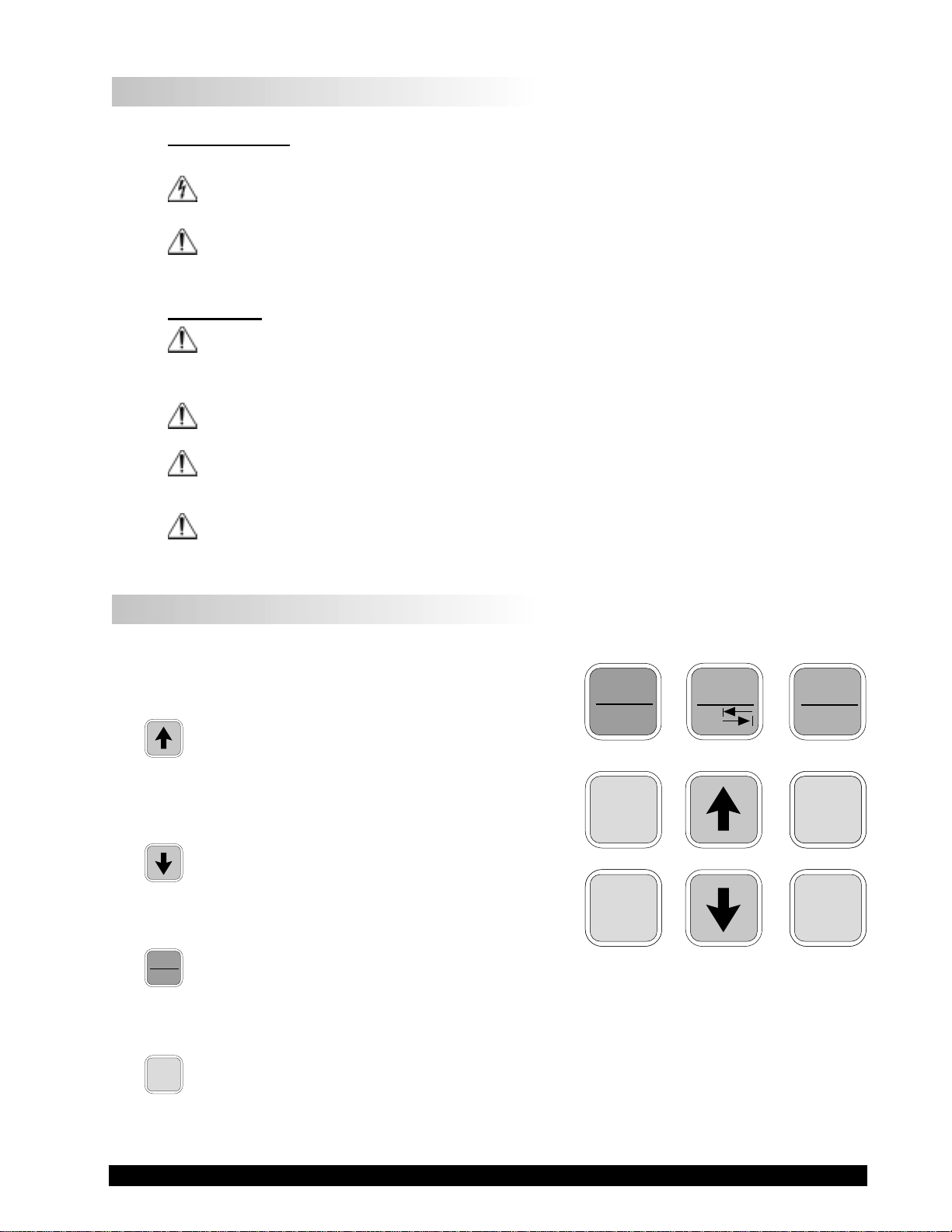
I.6 Key Functions
Figure 1 shows the control keys on the face of the DVII+ Viscometer. The following describes the function
of each key.
UP ARROW
This key is used to scroll UP (in an increasing
value direction) through the available speed,
spindle and Option menu tables.
DOWN ARROW
This key is used to scroll DOWN (in a decreasing
value direction) through the available speed,
spindle and option menu tables.
MOTOR
ON/OFF
ESCAPE
MOTOR ON/OFF/ESCAPE
Turns the motor ON or OFF. ESCAPE exits the
Options menu.
MOTOR
ON/OFF
ESCAPE
SET
SPEED
SELECT
DISPLAY
OPTIONS
TAB
Figure 1
ENTER
AUTO
RANGE
SELECT
SELECT
SPINDLE
SPINDLE
SET
SPEED
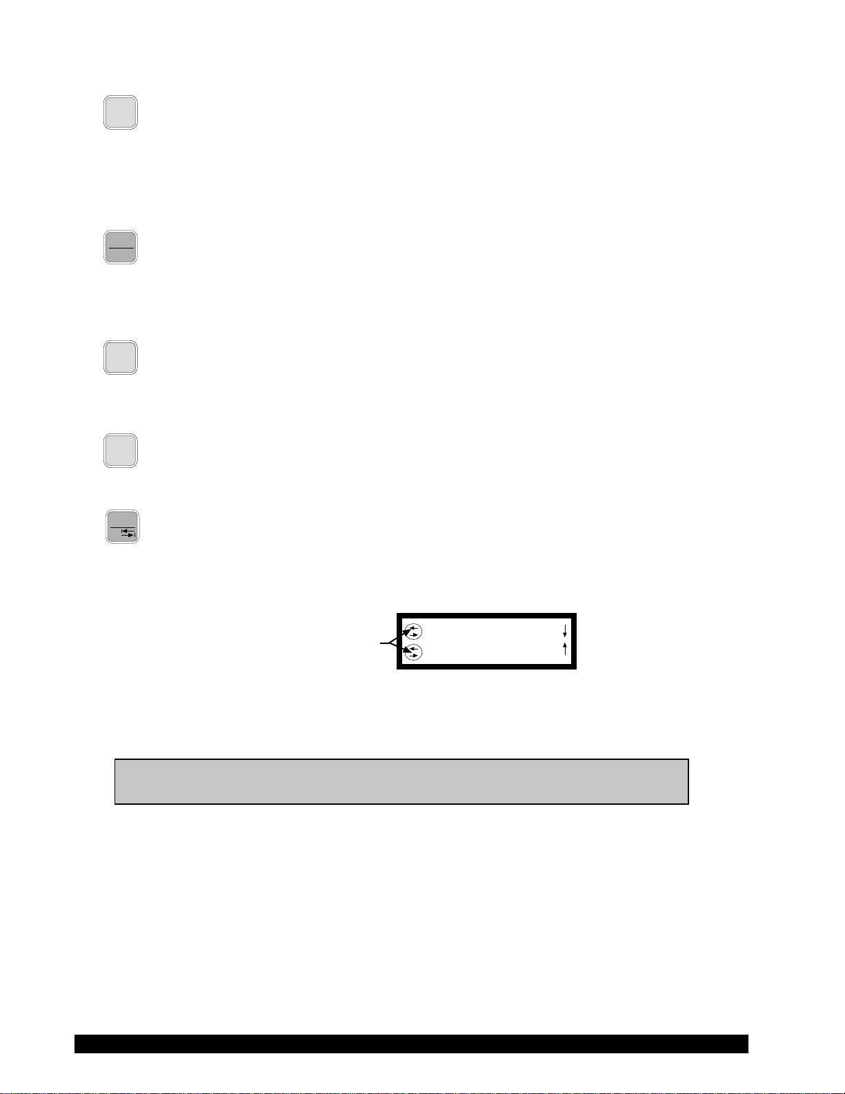
SET SPEED
Causes the DV-II+ to begin running at the currently selected speed. This function works
only when the motor is ON. Also used to select custom speeds when in the Custom Speed
option.
Brookfield Engineering Labs., Inc. Page 7 Manual No. M/97-164-F1 102
SELECT
DISPLAY
ENTER
AUTO
RANGE
SELECT
SELECT
SPINDLE
SPINDLE
SELECT DISPLAY
Selects the data parameter to be displayed:
cP Viscosity (cP or mPa.s)
SS Shear Stress (dynes/cm2 or Newtons/m2)
SR Shear Rate (1/sec)
ENTER/AUTO RANGE
ENTER: Used to execute the currently flashing option.
AUTO RANGE: Presents the maximum (100% torque) viscosity attainable using the
selected spindle at the current viscometer spindle speed.
SELECT SPINDLE
Initiates spindle selection on the first press and then selects the currently scrolled-to spindle
when pressed a second time.
Selects printing and non-printing modes when a printer is attached.
OPTIONS
TAB
OPTIONS/TAB
OPTIONS: Presents the Options menu, flashing the last escaped option.
TAB: Toggles between selectable items when indicated, as shown in Figure 2.
Note: Symbol indicating the
OPTIONS/TAB key
Note: Inverted text (black background with white lettering) indicates that the
information is flashing on the viscometer display.
L°F(FAHRENHEIT)
CGS UNITS
Figure 2
Brookfield Engineering Labs., Inc. Page 8 Manual No. M/97-164-F1102

I.7 Cleaning
Be sure to remove the spindle from the instrument prior to cleaning. Severe instrument damage may result if the spindle is cleaned in place.
Instrument and Keypad: Clean with a dry, non-abrasive cloth. Do not use solvents
or cleaners.
Immersed Components (spindles): Spindles are made of stainless steel. Clean with a non-
abrasive cloth and solvent appropriate for sample material.
Note: When cleaning, take care not to apply excessive force — it may bend the spindles.
Brookfield Engineering Labs., Inc. Page 9 Manual No. M/97-164-F1 102
II. GETTING STARTED
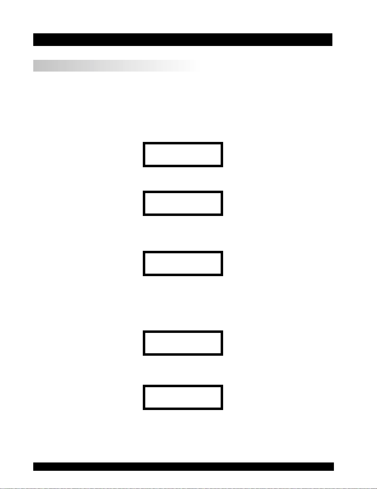
II.1 Autozero
Before readings may be taken, the Viscometer must be Autozeroed. This action is performed each
time the power switch is turned on. The display window on the Viscometer will guide you through
the procedure as follows:
Turn the power switch (located on the rear panel) to the ON position. This will result in the screen
display shown in Figure 3. The viscosity measurement range is indicated by the information in the
lower left, in this case RV. For most DV-II+ Viscometers, this information will be either “LV” or
“RV”.
BROOKFIELD DV-2+
RV VISCOMETER
Figure 3
After a few seconds, the following screen appears:
BROOKFIELD DV-2+
VERSION: 6.1
Figure 4
No key press is required at this point. After a short time, the display will clear and the following
will be displayed:
REMOVE SPINDLE
PRESS ANY KEY
Figure 5
After removing the spindle and pressing any key, the DV-II+ begins its Autozero. The screen will
flash «Autozeroing.»
After approximately 15 seconds, the display shows the screen in Figure 6:
REPLACE SPINDLE
PRESS ANY KEY
Figure 6
Pressing any key at this point results in the display of the DV-II+ default screen:
CP 0.0 20.1C
OFFRPM % 0.0
Figure 7
The display will vary depending upon the selection of temperature (°F or °C) and units of viscosity
(cP or mPa•s).
Brookfield Engineering Labs., Inc. Page 10 Manual No. M/97-164-F1102

SELECT
SELECT
II.2
Spindle Selection
SPINDLE
SPINDLE
LVDV-II+ Viscometers are provided with a set of four spindles and a narrow guardleg; RVDV-II+
Viscometers come with a set of six spindles and a wider guardleg; HADV-II+ and HBDV-II+
Viscometers come with a set of six spindles and no guardleg. (See Appendix E for more information
on the guardleg.)
The spindles are attached to the viscometer by screwing them onto the lower shaft. Note that the
spindles have a left-hand thread. The lower shaft should be secured and slightly lifted with one hand
while screwing the spindle to the left. The face of the spindle nut and the matching surface on the
lower shaft should be smooth and clean to prevent eccentric rotation of the spindle. Spindles can be
identified by the number on the side of the spindle coupling nut.
The DV-II+ must have a Spindle Entry Code number to calculate Viscosity, Shear Rate and Shear
Stress values. The DV-II
+ memory contains parameters for all standard Brookfield spindles
including custom spindles and the two digit entry code for each spindle (the complete list of entry
codes may be found in Appendix D).
Note: The DV-II+ will remember the Spindle Entry Code which was in use when the
power was turned off.
Pressing the SELECT SPINDLE key will display the current selected spindle code instead of
temperature and cause the character S to begin to blink . It will blink for about three seconds. If the
UP or DOWN ARROW keys are pressed (while S is blinking) the two character spindle value to the right
of the S character will begin to change (in either an increasing or decreasing direction depending upon
which ARROW key is pressed) for each press of the key. If the ARROW key is pressed and held, the
display will scroll through the spindle codes for as long as the ARROW key is depressed. When it
reaches the last item in the list (either at the top or bottom of the list) the spindle code displayed will
“roll-over” to either the first or last spindle code and the scroll action will continue.
When the desired spindle code is displayed, release the ARROW key to halt further scrolling. Press
the SELECT SPINDLE key once again. This will cause the S character to cease blinking and the new
spindle code will be accepted for use in viscometer calculations.
Note: You have approximately three seconds in which to press the SELECT SPINDLE
key before the
before the
the desired spindle.
blinking
blinking
stops. If you fail to press the SELECT SPINDLE key
stops you will have to repeat the above steps and re-select
The DV-II+ will begin to calculate using the new spindle parameters as soon as the SELECT SPINDLE
key is pressed the second time.
Note: The number 99 spindle is for use with special spindles when using Brookfield’s
WINGATHER computer program. Refer to the WINGATHER operator manual for
further information on using “99” spindles.
The DV-II+ may also be programmed at Brookfield Engineering for “special” user spindles. These
“special” spindles will appear on the spindle scroll list starting with designation “AA” and continuing
through “AZ”. Contact Brookfield Engineering regarding your needs for special spindles.
Brookfield Engineering Labs., Inc. Page 11 Manual No. M/97-164-F1 102
II.3
Speed Selection, Setting, Running
SET
SPEED
There are 54 speeds programmed into the DV-II+. These speeds correspond to the standard LVT,
RVT, HAT and HBT dial models (18 possible speeds altogether) plus 36 additional speeds.
The DV-II+ comes with the Sequential Speed Set already selected (see Appendix F). The speed set
will start at speed 0.0. It will then scroll up through the LV speeds, pass through speed 0.0 again, and
then scroll up through the RV speeds, pass through speed 0.0 again and then repeat the above
sequence.
The DV-II
+ can also be configured by the operator to interleave the LV and RV speeds. See Section
III.2.3 on Setup for a description of how to install the Interleave Speed Set.
A complete list of speed sets and custom speeds is included in Appendix F. The DV-II+ can be
programmed to select up to 19 of the 54 speeds for use at any one time. Speed 0.0 is the 20th speed
and is automatically included. See Section III. 2.3.2 on Setup for a description of how to install a
Custom Speed Set.
To select a Viscometer speed first press either the
UP or DOWN arrow keys which will cause the area
to the right of RPM to display the currently selected speed. Figure 8 shows the DV-II+ is operating
at 6.0 RPM, and the current selected speed is 6.0 RPM.
cP 123.4 20.1C
6.0RPM6.0 % 15.6
Figure 8
If the ARROW key is pressed just once and then released, the characters “RPM” will blink for three
seconds, then will cease blinking resulting in no change to the speed entry.
Note: The speed selection process remembers the last value of scrolled-to speed so
that the next time you initiate a speed change (by pressing an ARROW key), the
DV-II+ will begin its scroll display from the last entered value.
The last-scrolled-to speed does not necessarily have to be the same as the speed at which the DVII+ is currently running. The user may operate at a given speed and pre-set the DV-II+ to the next
desired speed before that speed will be used. For example, if the DV-II+ is currently running at 6.0
RPM and was previously scrolled to 12 RPM, a single press of either ARROW key would result in
the Figure 9 screen display:
cP 123.4 20.1C
6.0RPM12 % 15.6
Figure 9
Pressing the SET SPEED key would cause the DV-II+ to begin running at 12 RPM.
If the user did not press the SET SPEED key, the DV-II+ would continue to run at its current speed
of 6 RPM. In fact, you may scroll to a new speed (12 RPM in this example) and press the SET SPEED
key at any future time (without further pressing an ARROW key) to immediately cause the DV-II+
to run at the new speed. Pressing the ARROW key at any time reminds the operator of what was
selected for the next speed.
Brookfield Engineering Labs., Inc. Page 12 Manual No. M/97-164-F1102
If an ARROW key is pressed and held the DV-II+ will scroll up (or down) through the speed table.
When it reaches the last speed in the list (either at the top or bottom of the list) the speed displayed
will “roll-over” to either the first or last speed in the table and the scroll action will continue.
When the required speed is displayed, release the ARROW key to halt further scrolling. You have
approximately two seconds (before the blinking RPM stops) in which to press the SET SPEED key
to immediately begin rotation at the new speed.
Pressing the MOTOR ON/OFF/ESCAPE key stops the Viscometer spindle rotation. Pressing this key
sets the DV-II+ to 0.0 RPM and causes the screen display to change as shown in Figure 10:
cP 0.0 20.1C
OFFRPM % 0.0
Figure 10
Pressing the MOTOR ON/OFF/ESCAPE key again immediately starts the DV-II+ running at the last
scrolled-to-speed. If you had been running at 12 RPM, pressed MOTOR ON/OFF/ESCAPE and then
re-started the DV-II+ by pressing MOTOR ON/OFF/ESCAPE once again, you would again be running
at 12 RPM. However, if while the motor was off you had scrolled to a new speed of 0.5 RPM, pressing
the MOTOR ON/OFF/ESCAPE key would start the DV-II+ running at 0.5 RPM.
Note: During both spindle or speed selection and scrolling operations, the DV-II+ will
continue to calculate and display Viscometer data as selected.
SELECT
DISPLAY
II.4
Display Selection
Viscosity (displayed in units of cP or mPa•s), Shear Stress and Shear Rate are displayed on the left
side of the top line. You may “step” through the three display options by pressing the SELECT
DISPLAY key. For example, the DV-II+ is currently displaying Viscosity as shown in Figure 11:
cP 123e3 20.1C
6.0RPM % 15.6
Figure 11
If the viscosity value exceeds 99,999 scientific notation is used. In Figure 11, the viscosity value is
123,000 cP.
The first press of the SELECT DISPLAY key would display Shear Stress (SS) in Dynes/cm2 (or
Newtons/m2), see Figure 12:
SS 29.0 20.1C
6.0RPM % 15.6
Figure 12
If the shear stress value exceeds 99,999, scientific notation is used.
The next press of the SELECT DISPLAY key would display Shear Rate (SR) in 1/Sec; see Figure 13.
Brookfield Engineering Labs., Inc. Page 13 Manual No. M/97-164-F1 102
SR 40.0 20.1C
6.0RPM % 15.6
Figure 13
One more press of the SELECT DISPLAY key would result in a return to the viscosity screen, as shown
in Figure 11.
Notes: 1. You may step through the display at any time. This will not interrupt any
Viscometer calculations that are in progress.
2. Display of shear rate and shear stress requires selection of appropriate
spindles. Otherwise, values displayed will be zero (0).
Units of Measurement
The DV-II+ Viscometer can be configured using the SETUP option (Section III.2.2) to display/
print in either the CGS or SI system of units.
ENTER
II.5
The ENTER/AUTO RANGE key functions as auto range and allows you to determine the maximum
calculated viscosity (full scale reading) possible with the current spindle/speed setting only when in
the default screen. Pressing the key at any time will cause the current viscosity display to change and
show that maximum viscosity. The screen area displaying % (torque) will now display a flashing
“%100.0” to indicate this special condition. This maximum viscosity and flashing %100.0 value will
be displayed for as long as the ENTER/AUTO RANGE key is depressed. Figure 14 shows the AUTO
RANGE function for the situation where the No. 1 LV spindle is rotating at 60 rpm. The full scale
range is 100.0 cP (or 100.0 mPa.s).
Autorange
AUTO
RANGE
cP 100.0 S61
60 RPM % 100
Figure 14
Notes: 1. If the RPM is 0.0, the maximum viscosity displayed will be 0.0 cP (or 0.0
mPa.s).
2. While the Viscometer is in the Auto Range mode, any data sent to an
attached printer or computer reflects the displayed values (i.e. Auto Range
values).
3. This function is only available when in the default screen.
Brookfield Engineering Labs., Inc. Page 14 Manual No. M/97-164-F1102
II.6 Out of Range
The DV-II+ gives indications for out-of-range operation. When % (Torque) readings exceed 100%
(over-range), the display changes to that shown in Figure 15; EEEE will also appear in the display
for % and viscosity or shear stress:
cP EEEE 20.1C
10 RPM % EEEE
Figure 15
You must change either speed or spindle to correct this condition. If you operate at spindle speeds
that produce % (Torque) below 10.0 %, the DV-II+ flashes the % (Torque), cP (Viscosity), SS
(Shear Stress) and SR (Shear Rate) as shown in Figure 16:
cP 12.4 20.1C
10 RPM % 8.2
Figure 16
Negative % (Torque) will be displayed as shown in Figure 17:
cP —- 20.1C
10 RPM % -2.2
Figure 17
Figure 18 is an example of the printed output of each of the above conditions.
Normal Operation:
RPM=50 M=RV S=29 %=51.4 cP=10280 D/CM2=1285 1/SEC=12.3 T=20.1C Z00:30
Over-Range Operation (>100% torque) (see Fig. 15):
RPM=50 M=RV S=29 %=EEEE cP=EEEE D/CM2=EEEE 1/SEC=12.3 T=20.1C Z00:30
Under-Range Operation (<10% torque) (see Fig. 16):
?RPM=50 M=RV S=29 %=5.2 cP=1040 D/CM2=130 1/SEC=12.3 T=20.1C Z00:30
Negative Torque Operation (see Fig. 17):
RPM=50 M=RV S=29 %=-0.1 cP=—- D/CM2=—- 1/SEC=12.3 T=20.1C Z00:30
M = Torque Range T = Temperature Z = Time
Figure 18
Brookfield Engineering Labs., Inc. Page 15 Manual No. M/97-164-F1 102

II.7 Temperature Display
The DV-II
+ displays the temperature measured by its RTD temperature probe. Temperature may be
displayed in either ˚C (Centigrade) or ˚F (Fahrenheit) units, depending upon selection from the
Options menu. As received, the default temperature display will be in ˚C (Centigrade) units as shown
in the Figure 19:
cP 123.4 20.1C
10 RPM % 19.7
Figure 19
If you turn on the DV-II+ with the temperature probe disconnected, or remove the temperature probe
at any point after power-up, the display will indicate “- — — -C”. The four “dashes” indicate the absence
of the probe. If you were displaying temperature in Fahrenheit units the C would be replaced by an
F. Accuracy of temperature measurement for the DV-II+ is shown in Table 1.
Table 1
Temperature Accuracies for
Programmable DV-II+ Viscometer
Temperature Range Temperature Accuracy
-100°C to +149°C ±1.0°C
+150°C to +300°C ±2.0°C
II.8
Printing
The DV-II+ will print data to an attached Serial (RS232) or Parallel (centronics) printer. The printer
must be attached to the appropriate rear panel output connector. See Appendix G for configuration
and connection requirements.
Data may be printed in two ways:
1. Pressing the PRINT key once (for less than three (3) seconds) will result in the printing of one
standard print line.
2. If the PRINT key is pressed and held for more than three (3) seconds, the DV-II+ will then begin
continuous printer output at a print rate interval selected via the Options menu (see Section III.4).
The display will show a flashing P in front of the % sign. See Figure 20.
cP 123.4 20.1C
10 RPM P% 19.7
Figure 20
To stop continuous printing, press the PRINT key for one (1) second. The flashing P will
disappear on the viscometer display.
Figure 21 is an example of the print strings for CGS and SI units.
Brookfield Engineering Labs., Inc. Page 16 Manual No. M/97-164-F1102
For the case of CGS units with non-exponential results:
11020304050607080
RPM=XXX M=XXXXX S=XX %=XXX.X cP=XXXXX D/CM2=XXXXX 1/SEC=XXXXX T=XX.XC ZXX=XX
and CGS units with exponential results.
11020304050607080
RPM=XXX M=XXXXX S=XX %=XXX.X cP=XXXeX D/CM2=XXXeX 1/SEC=XXXXX T=XX.XC ZXX=XX
Similarly, for SI units with non-exponential results.
11020304050607080
RPM=XXX M=XXXXX S=XX %=XXX.X mPas=XXXXX N/M2=XXXXX 1/SEC=XXXXX T=XX.XC ZXX=XX
and SI units with exponential results.
11020304050607080
RPM=XXX M=XXXXX S=XX %=XXX.X mPas=XXXeX N/M2=XXXeX 1/SEC=XXXXX T=XX.XC ZXX=XX
M = Torque T = Temperature Z = Time
Figure 21
When printing via the parallel port, please note that if a printer is not attached to the viscometer,
the following screen appears:
PRINTER ERROR
CHECK CONNECTION
Figure 22
II.9 Making Viscosity Measurements
The following general procedure is used for making viscosity measurements. Brookfield recommends the use of a 600 ml Low Form Griffin beaker when using LV/RV/HA/HB spindles.
1. Mount the guardleg on the DV-II+ Viscometer (LV and RV series) and insert into the container.
2. Insert and center spindle in the test material until the fluid’s level is at the immersion groove on
the spindle’s shaft. With a disc-type spindle, it is necessary to tilt the spindle slightly while
immersing to avoid trapping air bubbles on its surface. Attach the spindle to the lower shaft of
the viscometer. Lift the shaft slightly, holding it firmly with one hand while screwing the spindle
on with the other (note left-hand thread). Avoid putting side thrust on the shaft. Verify the proper
spindle immersion depth and that the viscometer is level.
3. The process of selecting a spindle and speed for an unknown fluid is normally trial and error. An
appropriate selection will result in measurements made between 10-100 on the instrument
% torque scale. Two general rules will help in the trial and error process.
1) Viscosity range is inversely proportional to the size of the spindle.
2) Viscosity range is inversely proportional to the rotational speed.
To measure high viscosity, choose a small spindle and/or a slow speed. If the chosen spindle/
speed results in a reading above 100%, then reduce the speed or choose a smaller spindle.
Experimentation may reveal that several spindle/speed combinations will produce satisfactory
results between 10-100%. When this circumstance occurs, any of the spindles may be selected.
Brookfield Engineering Labs., Inc. Page 17 Manual No. M/97-164-F1 102

Non-Newtonian fluid behavior can result in the measured viscosity changing if the spindle and/
or speed is changed. See our publication, “More Solutions to Sticky Problems,” for more detail.
Turn on motor.
Allow time for the indicated reading to stabilize. The time required for stabilization will depend
on the speed at which the Viscometer is running and the characteristics of the sample fluid. For
maximum accuracy, readings below 10% should be avoided.
Record values.
4. Press the
MOTOR ON/OFF/ESCAPE key and turn the motor “OFF” when changing a spindle or
changing samples. Remove spindle before cleaning.
5. Interpretation of results and the instrument’s use with non-Newtonian and thixotropic materials
is discussed in the booklet, «More Solutions to Sticky Problems», and in Appendix C, Variables
in Viscosity Measurements.
II.10 Time Modes for Viscosity Measurement
The Time Modes allow the viscometer user to implement the unattended Time to Stop and Time to
Torque capabilities of the DV-II+ Viscometer. These features will allow the user to set up the
viscometer (i.e. select spindle and speed) and then record readings for a fixed period of time (Time
to Stop) or until a set torque value is attained (Time to Torque). When timing begins, a message will
be displayed showing time remaining (or time elapsed) and the appropriate display item (viscosity
or torque) will be updated continuously during the event. Upon completion, the viscometer will stop
and display a screen stating that the test is complete and will also display the final recorded value for
the viscosity in the first case, or the time in minutes and seconds to reach the torque limit in the second
case. Pressing the UP or DOWN ARROW keys will allow additional viscometer data to be examined.
Pressing any other key (except the PRINT or ENTER/AUTORANGE key) will bring the user back to the
default (normal) viscometer display with the motor OFF. Refer to the Time Modes in Section III.3.
Brookfield Engineering Labs., Inc. Page 18 Manual No. M/97-164-F1102

III. OPTIONS
OPTIONS
III.1
The OPTIONS/TAB key provides access to the configuration (Setup) of the DV-II+ Viscometer as
well as special functions that can enhance the user’s ability to make viscosity measurements.
The Options menu, shown in Table 1, gives a complete picture of the various configuration
choices and special functions.
Quick References to Options
Introduction to OPTIONS
TAB
SETUP:
Temperature — °F or °C
Units — CGS or SI
* Speed Sets — Sequential, Interleave, Custom
Printer Port — Serial (RS232) or Parallel
Data Averaging — Display Only
Table 2
Options Menu
* TIME TO STOP
* TIME TO TORQUE
SET PRINT TIME:
Set the Printing Time
PC PROG (ON/OFF):
Enables/Disables Communication of Serial (RS232) Port
* DOWNLOAD A PROGRAM:
Link to PC to Receive a B.E.V.I.S. Program
(B.E.V.I.S. = Brookfield Engineering Viscometer Instruction Set)
* RUN A PROGRAM:
Execute a B.E.V.I.S. Program
*Not available when motor is ON
Pressing OPTIONS/TAB places you into the Options menu at the last option selected. The following
keys are active and perform as follows:
UP ARROW — Scrolls up through menu or selects new value from
list.
DOWN ARROW — Scrolls down through menu or selects new value
from list.
Brookfield Engineering Labs., Inc. Page 19 Manual No. M/97-164-F1 102
OPTIONS
OPTIONS/TAB — Toggles between options.
TAB
ENTER
ENTER/AUTORANGE — Accepts the currently flashing option and moves
AUTO
RANGE
user to next level (if applicable) of the selected
option.
MOTOR
ON/OFF
MOTOR ON/OFF/ESCAPE — Cancels current operation and backs user out one
ESCAPE
menu level. Repeated pressing will back the user
out to the default screen. While in the Options
menu, the
MOTOR ON/OFF/ESCAPE key does not
cause the viscometer motor to turn on or off!
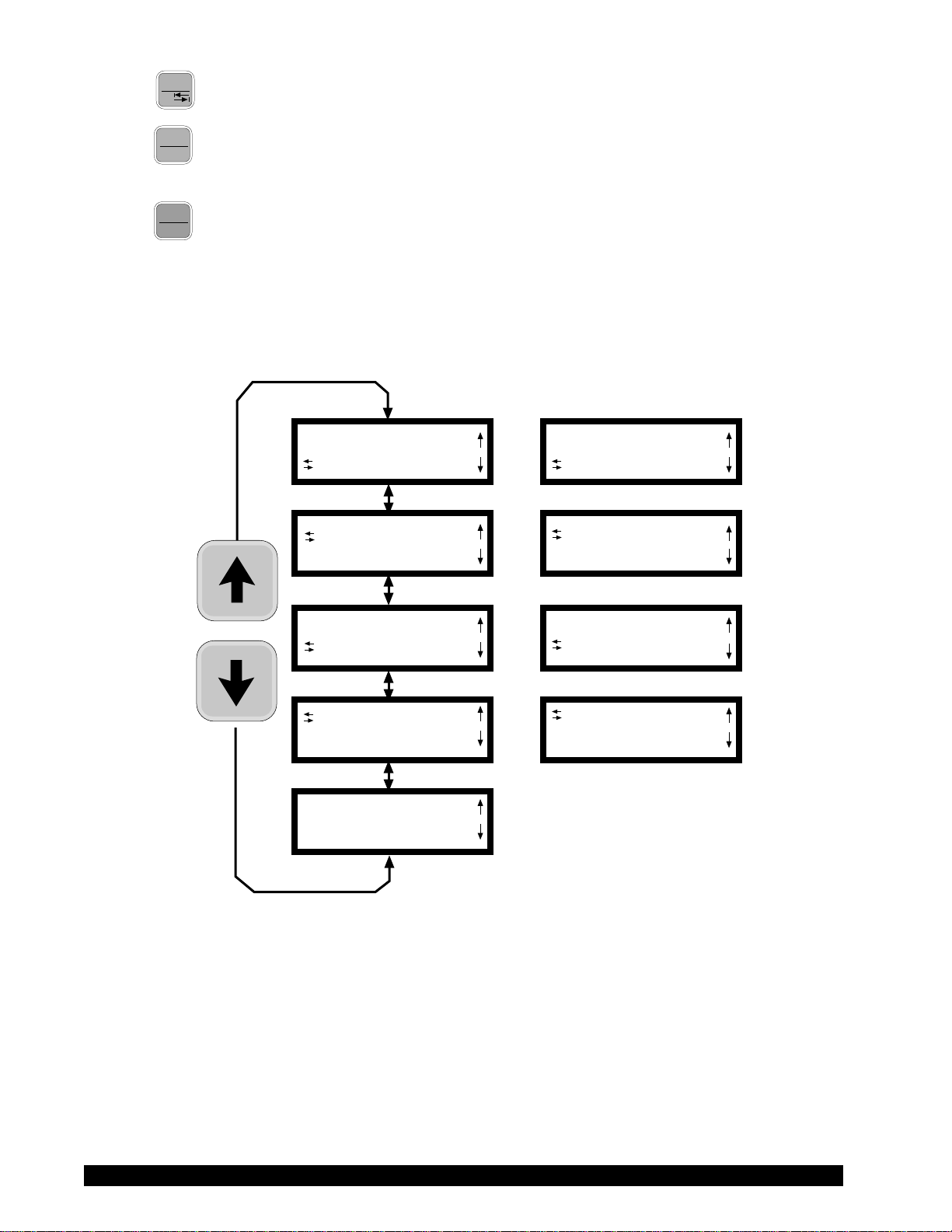
The Options menu screens will appear as shown in Figure 23 if you cycle through the
possible options using the
UP/DOWN arrows.
SETUP
TIME TO TORQUE
TIME TO TORQUE
SET PRINT TIME
SET PRINT TIME
PC PROG OFF
PC PROG OFF
DOWNLOAD A PROG
DOWNLOAD A PROG
RUN A PROG
OR
OR
OR
OR
SETUP
TIME TO STOP
LTIME TO STOP
SET PRINT TIME
SET PRINT TIME
PC PROG ON
LPC PROG ON
DOWNLOAD A PROG
Figure 23
On entry to the Options menu, the following rules regarding current viscometer operation are in force:
1. Printer output will be suppressed when in the Custom Speed option, the Time to
Torque and Time to Stop options, the Download A Program and Run A Program
options. It will be continued when any other option is selected.
2. If the motor is ON when the user enters the Options menu, choices will be limited
to: CGS/SI units (under SETUP), °F/°C units (under SETUP), PRINTING SELECTIONS and PC PROG.
3. The last selected menu option will be flashing.
Brookfield Engineering Labs., Inc. Page 20 Manual No. M/97-164-F1102
Selecting an Option
The following is a quick reference for entering and using the OPTIONS menu:
Press
Press
OPTIONS
TAB
To enter Options Menu
or To scroll to a specific option
For Options:
Press
Press
OPTIONS
TAB
ENTER
AUTO
RANGE
To toggle between the choices available for a specific option when indicated
To select the flashing option
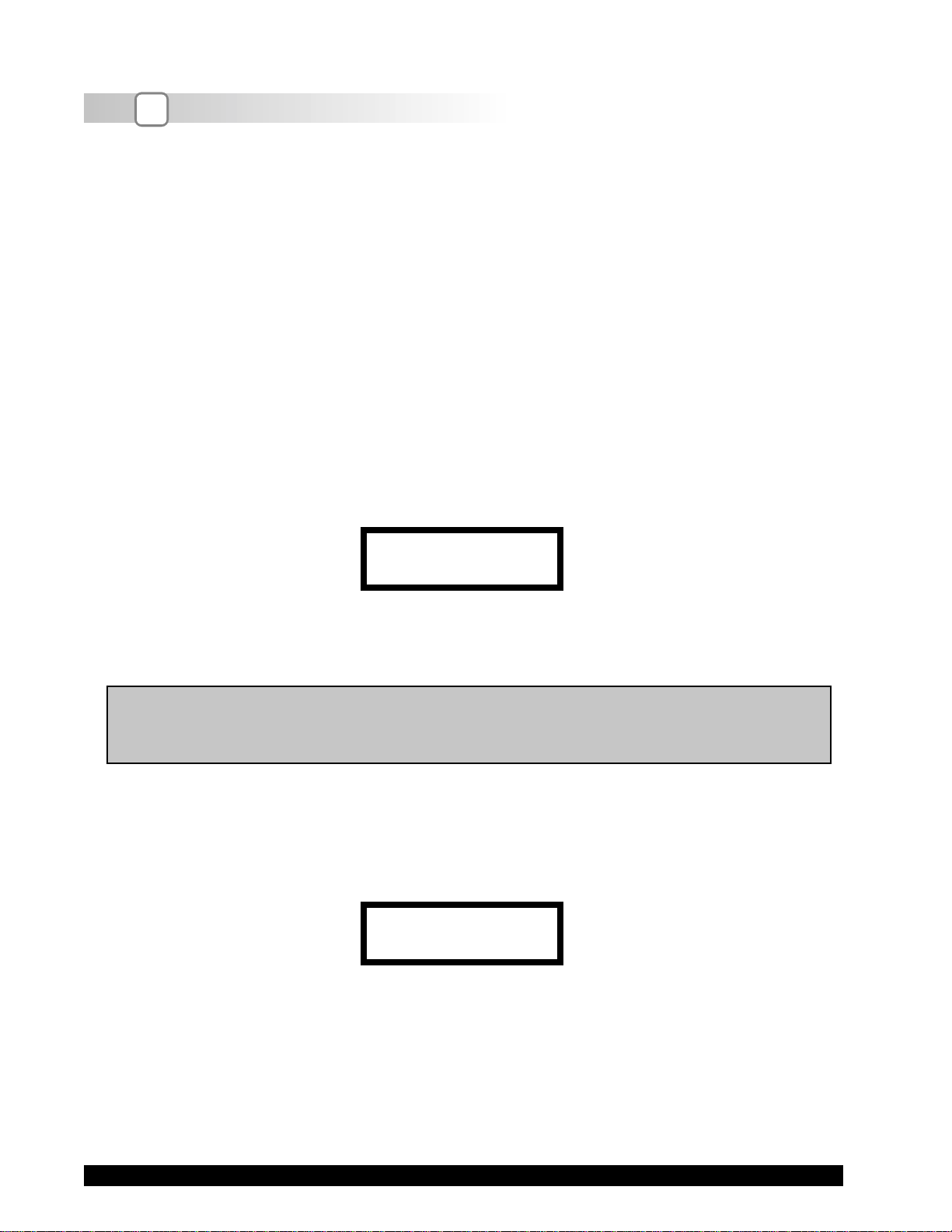
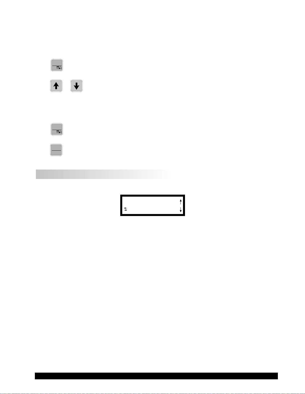
III.2 Setup
From the main Options screen, the user scrolls up or down until the following screen is displayed:
SETUP
TIME TO TORQUE
Figure 24
A press of the ENTER/AUTORANGE key takes you into the Setup sub-menu (Figure 25). As in the
main Options menu, you can scroll up or down through the various Setup options. In order to access
all options, the motor must be turned off.
Brookfield Engineering Labs., Inc. Page 21 Manual No. M/97-164-F1 102
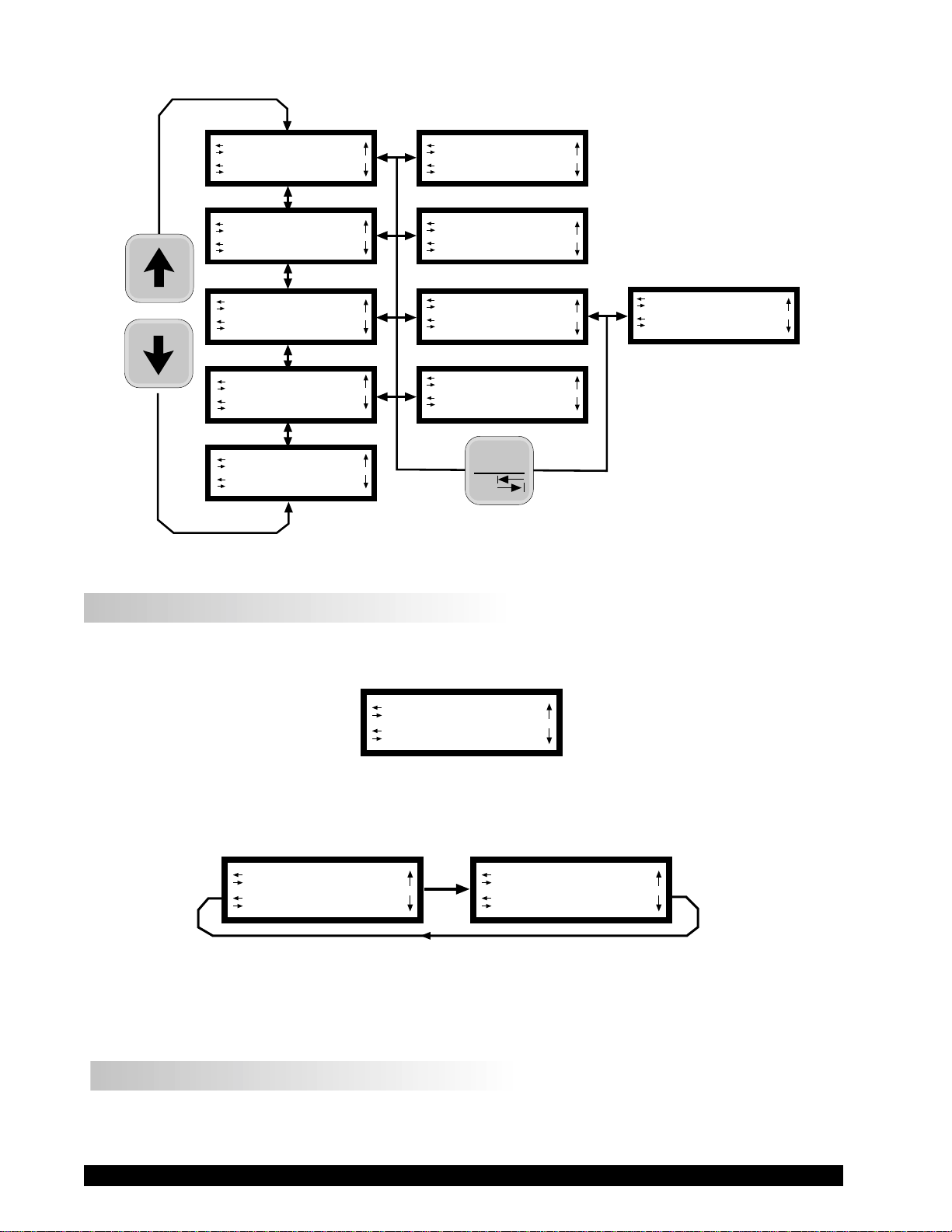
L°F(FAHRENHEIT)
CGS UNITS
L°C(CENTIGRADE)
CGS UNITS
L°F(FAHRENHEIT)
CGS UNITS
LCGS UNITS
SEQUENTIAL
LSEQUENTIAL
PRINT SERIAL
LPRINT SERIAL
DATA AVERAGING
L°F(FAHRENHEIT)
SI UNITS
LCGS UNITS
INTERLEAVE
LSEQUENTIAL
PRINT PARALLEL
OPTIONS
TAB
Figure 25
LCGS UNITS
CUSTOM SPEEDS
III.2.1 Temperature Display
The DV-II+ viscometer can display temperature in either degrees Centigrade or degrees Fahrenheit.
On entry (assuming the viscometer is currently displaying °F) you will be presented with:
L°F(FAHRENHEIT)
CGS UNITS
Figure 26
A press of the OPTIONS/TAB key at this point will “toggle” between the two available temperature
scale options as shown in Figure 27:
L°F(FAHRENHEIT)
CGS UNITS
Figure 27
To select the temperature display mode, press the ENTER/AUTORANGE key. You automatically exit
the Setup menu with the viscometer displaying temperature in the selected scale. You must press the
ENTER/AUTORANGE key to select the flashing option.
III.2.2 Units of Measurement
Selecting units of measurement is identical to that for temperature described above. The screen
display shows:
L°C(CENTIGRADE)
CGS UNITS
Brookfield Engineering Labs., Inc. Page 22 Manual No. M/97-164-F1102
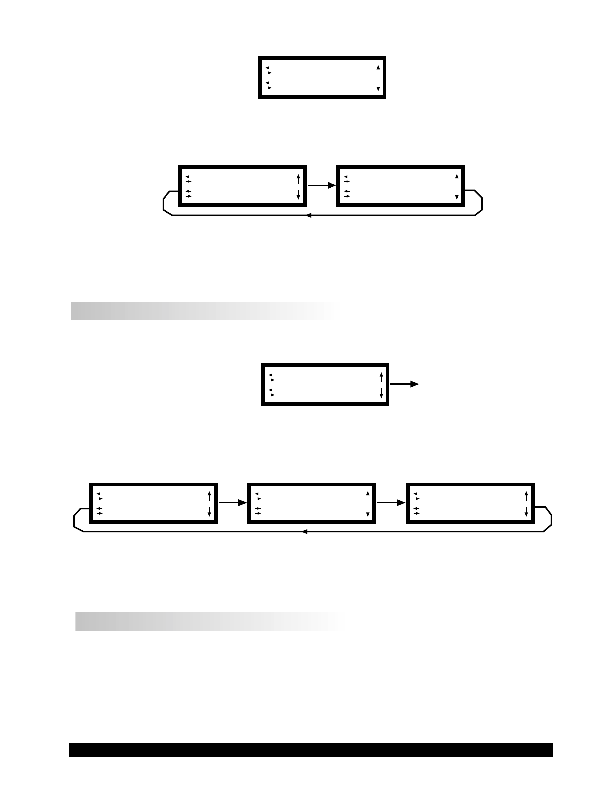
L°F(FAHRENHEIT)
CGS UNITS
Figure 28
A press of the OPTIONS/TAB key at this point allows the user to “toggle” between the two available
data display units as shown in Figure 29:
L°F(FAHRENHEIT)
CGS UNITS
Figure 29
L°F(FAHRENHEIT)
SI UNITS
Pressing the ENTER/AUTORANGE key selects the display units, which are flashing, followed by an
exit of the Setup menu. You must press the ENTER/AUTORANGE key to select the flashing option.
III.2.3 Motor Speed Set Selection
This selection must be done with the motor off. Scrolling in the Setup options menu to the speed set
selection option yields the following screen display:
LCGS UNITS
SEQUENTIAL
Figure 30
The last selected speed set option is displayed, in this case, Sequential. For each press of the
OPTIONS/TAB key, the display shows selectable options (Figure 31). You must press the ENTER/
AUTORANGE key to select the flashing option.
LCGS UNITS
INTERLEAVE
LCGS UNITS
CUSTOM SPEEDS
Figure 31
LCGS UNITS
SEQUENTIAL
The speeds available in each of the above options are listed in Appendix F. The DV-II+ is initially
set up with the Sequential Speed Set at Brookfield prior to shipment.
III.2.3.1 LV/RV Speeds
In the case of Sequential or Interleave, a press of the ENTER/AUTORANGE key immediately selects
that option and exits the SETUP option menu.
Brookfield Engineering Labs., Inc. Page 23 Manual No. M/97-164-F1 102
Loading…
Ротационный вискозиметр Brookfield DV2TRV.
Особенности и преимущества
* 5–дюймовый полноцветный сенсорный дисплей
* Усовершенствованный контроль
* Индикатор измерения в режиме реального времени
* Поддержка нескольких языков интерфейса
Повышенная безопасность
* Настраиваемый доступ пользователя
* Файл фиксации даты и времени анализа
…
Перейти к полному описанию >
Ротационный вискозиметр Brookfield DV2TRV.
Особенности и преимущества
- 5–дюймовый полноцветный сенсорный дисплей
- Усовершенствованный контроль
- Индикатор измерения в режиме реального времени
- Поддержка нескольких языков интерфейса
Повышенная безопасность
- Настраиваемый доступ пользователя
- Файл фиксации даты и времени анализа
- Защищенный паролем доступ
- Мобильные настройки регистрации
Встроенные опции
- Испытания на скорость
- Усреднение данных
- Программируемые пределы контроля качества/аварийные сигналы
- Настраиваемые списки скорости/шпинделя
- Инструкции для пользователя в зависимости от испытания
- Экранное сравнение данных
Отображаемая информация
- Вязкость (сПз или мПа•с)
- Температура (°C или °F)
- Скорость сдвига/напряжение сдвига
- Крутящий момент %
- Скорость вращения/шпиндель
- Статус текущего шага выполнения программы
Программа RheocalcT (дополнительная)
Программа Rheocalc обеспечивает автоматическое управление и сбор данных с использованием компьютера. Rheocalc может анализировать данные, накладывать несколько графиков друг на друга, распечатывать табличные данные, рассчитывать математические модели и выполнять другие экономящие время операции. Можно графически отобразить и сохранить до пяти сравниваемых наборов данных.
Дополнительные функции программы
- Встроенные подсказки, обеспечивающие пошаговое создание стандартных тестов
- Функции с поддержкой циклов для решения повторяющихся задач
- Усреднение собранных данных по шагам или в целом для испытания
- Возможно математическое моделирование: Bingham, Casson, Casson NCA/CMA, Power Law, IPC Paste, Herschel-Bulkley, Thix Index
| Диапазон вязкости, сПз (мПа*с) | Скорости | |||
| Модель | Мин. | Макс. | Об./мин. | Число скоростей |
| DV2TLV | 1** | 6000000 | 0,1 — 200 | 200 |
| DV2TRV | 100 | 40000000 | 0,1 — 200 | 200 |
| DV2THA | 200 | 80000000 | 0,1 — 200 | 200 |
| DV2THB | 800 | 320000000 | 0,1 — 200 | 200 |
** — 1 сПз достигается с UL адаптером, 15 сПз для модели LV со стандартными шпинделями.
- Набор из 6 шпинделей (RV/HA/HB)
- Специализированная программа PG Flash
- Температурный датчик RTD
- Предохранительная подставка для шпинделя
- Лабораторный штатив (модель G)
- Набор инструментов для техобслуживания (флеш-накопитель USB, стилус, салфетка для очистки)
- Кейс для хранения и переноски
- Руководство по эксплуатации
- Гарантийный талон
- Упаковка