
No. 2B771-004EN*M
OPERATION MANUAL
FOR
DIAGNOSTIC ULTRASOUND SYSTEM
MODEL TUS-A500
[FUNDAMENTALS]
(2B771-004EN*M)
CAUTION:
In the USA, federal law restricts this device to sale by
or on the order of a physician.
IMPORTANT!
Read and understand this manual before operating
the equipment. After reading, keep this manual in
an easily accessible place.
TOSHIBA MEDICAL SYSTEMS CORPORATION 2010-2014
ALL RIGHTS RESERVED

Introduction
This operation manual describes the operating procedures for the diagnostic ultrasound system
TUS-A500. To ensure safe and correct operation of the system, carefully read and understand
the manual before operating the system.
Trademarks
Windows® is a registered trademark of Microsoft Corporation in the United States and other
countries.
Clorox Healthcare is a trademark of The Clorox Company.
Dispatch® is a registered trademark of The Clorox Company.
Cleanisept® is a registered trademark of Dr. Schumacher GmbH.
Java is a registered trademark of Oracle and/or its affiliates.
APLIO, Dynamic Flow, ApliPure, MicroPure, and TwinView are trademarks of Toshiba Medical
Systems Corporation.
This manual may include trademarks or registered trademarks of other companies.
Note that the trademark symbol «» and the registered trademark symbol «» may or may not
be used in this manual.
IMPORTANT!
1. No part of this manual may be copied or reprinted, in whole or in part,
without prior written permission.
2. The contents of this manual are subject to change without prior notice
and without legal obligation.
3. The contents of this manual are correct to the best of our knowledge.
Please inform us of any ambiguous or erroneous descriptions, missing
information, etc.
No. 2B771-004EN*M
Organization of the Operation
Manuals
1. Notation Conventions
In this operation manual, the following word is used in addition to the signal words related to the
safety precautions (refer to section 2 «General Safety Information»). Please read this operation
manual before using the system.
NOTE: Indicates reference information that enables more efficient use of the equipment.
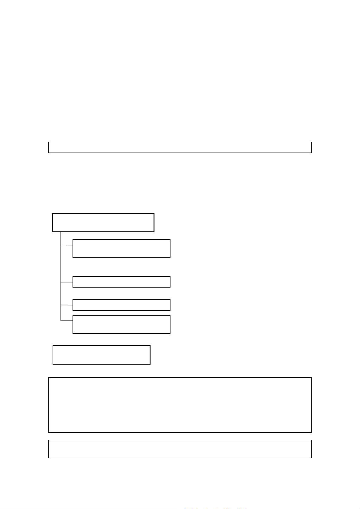
2. Operation Manuals
A TOSHIBA service person or instructor will explain the basic operating procedures for this
system at the time of delivery. However, read this operation manual carefully before using the
system in order to understand the detailed operating procedures, functions, performance, and
maintenance procedures.
Operation manual for the main unit
of the ultrasound system
Fundamentals volume
(this manual)
Applications volume
Measurements volume
Acoustic power and surface
temperature data
Operation manual for each
transducer
………………… Describes the operating and
……… Describes the basic information
concerning the system, such as
preparation for examination, operation,
inspection, and functional descriptions of
the system.
……… Describes the exam data manipulation
procedures and optional unit operation
procedures.
……… Describes the registration and
measurement procedures.
……… Describes the acoustic power
transmitted from the ultrasound
transducer.
disinfection/sterilization procedures for
the transducer.
NOTE: For certain applications, the following manuals are available in English:
2B771-005EN Applications volume
2B771-006EN Measurements volume
2B771-007EN Acoustic power and surface temperature data (For regions other
than the USA)
2B771-008EN Acoustic power and surface temperature data (For the USA only)
2B771-010EN Operation card
NOTE: The operation manuals Applications volume and Measurements volume may be
supplied on electronic media.
No. 2B771-004EN*M
U-1

3. Switch Configuration
The descriptions in this operation manual are based on the standard switch configuration. If
the switch configuration has been changed, the differences between the current configuration
and the standard configuration must be understood before use.
The layout, shapes, labels, and icons of the switches on the touch panel can be changed. All
the figures of touch panel and switches in this manual are examples and may differ from the
actual display.
4. Operation Switches
Some operations can be performed using either the switches on the main panel or the
corresponding switches on the touch panel.
The switches displayed on the touch panel differ depending on the selected exam type,
transducer, and mode.
No. 2B771-004EN*M
U-2
* *

Table of Contents
Organization of the Operation Manuals ……………………………………………… U-1
1. Intended Use …………………………………………………………………………. 1-1
1.1 Intended Medical Use ……………………………………………………………….. 1-1
1.2 Intended Patient Information …………………………………………………. 1-1
1.3 User Profile
1.4
Operating Principles ………………………………………………………………….. 1-1
…………………………………………………………………………………….. 1-1
2. General Safety Information ……………………………………. 2-1
2.1 Meaning of Signal Words ………………………………………………………… 2-1
2.2 Meaning of Safety Symbols …………………………………………………… 2-1
2.3 Ensuring the Safety of Patients and Operators ……………. 2-2
2.4 Preventing Electric Shocks, Fires, and
Power Supply Interruptions
2.5 Chemical Hazard …………………………………………………………………………. 2-5
2.6
Electromagnetic Compatibility (EMC) ……………………………….. 2-5
2.7 Acoustic Power ……………………………………………………………………………. 2-6
…………………………………………………… 2-3
2.8 Preventing System Malfunctions ………………………………………… 2-7
2.9 Handling Patient and Image Data ………………………………………… 2-9
2.10 Warning Labels ……………………………………………………………………………. 2-9
2.11 Regulatory Labels …………………………………………………………………….. 2-12
2.12 Precautions Concerning Clinical
Examination Techniques
No. 2B771-004EN*M
……………………………………………………….. 2-13
— a —

3. General Information on Usage and
Maintenance …………………………………………………………………………… 3-1
4. Use Conditions …………………………………………………………………… 4-1
4.1 Power and Environmental Requirements ……………………….. 4-1
4.2 Environmentally Friendly Usage and
Maintenance Management
……………………………………………………… 4-2
5. System Configuration ………………………………………………….. 5-1
5.1 Standard Configuration ……………………………………………………………. 5-1
5.2 List of Optional Units ………………………………………………………………… 5-1
5.3 Compatible Peripheral Devices ……………………………………………. 5-2
5.4 External Storage Devices ……………………………………………………….. 5-2
5.5 List of Optional Software ………………………………………………………… 5-3
5.6 List of Available Transducers ……………………………………………….. 5-4
6. Names and Functions of Each Section …….. 6-1
6.1 Name of Each Section ………………………………………………………………. 6-1
6.2 Main Panel ……………………………………………………………………………………… 6-3
6.3 Rear Panel ………………………………………………………………………………………. 6-7
6.4 Symbols …………………………………………………………………………………………… 6-8
7. Preparation for Examination ………………………………… 7-1
7.1 Moving and Installing the System ………………………………………. 7-1
7.2 Handling and Connecting/Disconnecting the
Transducer
7.2.1 Handling the transducer …………………………………………………………………. 7-4
…………………………………………………………………………………….. 7-4
No. 2B771-004EN*M
— b —

7.2.2 Connecting/Disconnecting the transducer …………………………………. 7-4
7.3 Adjusting the Main Panel ………………………………………………………… 7-6
7.4 Adjusting the Monitor ……………………………………………………………….. 7-8
7.4.1 Locking and releasing the monitor ………………………………………………. 7-8
7.4.2 Adjusting the angle of the monitor ……………………………………………….. 7-9
7.4.3 Adjusting the monitor display ……………………………………………………… 7-10
8. Checks Before and After Use ………………………………. 8-1
8.1 Checks Before Turning ON the Power ……………………………… 8-1
8.2 Checks After Turning ON the Power …………………………………. 8-2
9. Turning the Power ON/OFF ……………………………………. 9-1
9.1 Connecting the Power Cable and the
Protective Grounding
9.2 Turning ON the Power ………………………………………………………………. 9-4
9.3 Turning the Power OFF ……………………………………………………………. 9-6
9.4 Standby Mode ………………………………………………………………………………. 9-9
9.4.1 Setting Standby mode …………………………………………………………………….. 9-9
9.4.2 Recovery from the Standby status ……………………………………………… 9-11
9.5 Preparation for Use During Surgery or for
Emergency Cases
……………………………………………………………….. 9-2
…………………………………………………………………….. 9-12
9.5.1 Preparation of a backup system ………………………………………………….. 9-12
9.5.2 Power OFF/ON in the case of system failure …………………………….. 9-12
10. Basic Screen and Menu …………………………………………… 10-1
10.1 Display of Various Data Items …………………………………………….. 10-1
10.2 Displaying the Acoustic Power Data ……………………………….. 10-2
No. 2B771-004EN*M
— c —

10.3 Thumbnail Display ……………………………………………………………………. 10-4
11. Starting an Examination ………………………………………….. 11-1
11.1 Entering and Saving Data on the
[Patient Registration] Screen
………………………………………………. 11-2
12. Reference Signal Display ……………………………………….. 12-1
12.1 Reference Signal Panel ………………………………………………………….. 12-4
12.2 Installing the Reference Signal Sensor ………………………….. 12-5
12.3 Adjusting Reference Signals ……………………………………………….. 12-5
13. Common Operation for Each Mode …………….. 13-1
13.1 Touch Panel Operation …………………………………………………………… 13-1
13.2 Trackball Functions …………………………………………………………………. 13-8
13.2.1 Trackball function area ………………………………………………………………….. 13-8
13.2.2 Trackball operations ………………………………………………………………………. 13-9
13.3 Selecting an Imaging Preset During Examination …… 13-10
13.3.1 [DEFAULT PRESET] tab ………………………………………………………………. 13-12
13.3.2 [USER PRESET] tab ……………………………………………………………………… 13-15
13.3.3 [Sub Preset] menu ………………………………………………………………………… 13-15
13.4 Selecting an Application Preset
During Examination
……………………………………………………………….. 13-16
13.5 Changing the Transducer During
Examination
……………………………………………………………………………….. 13-18
14. Display and Operation in Each Mode ………… 14-1
14.1 2D Mode …………………………………………………………………………………………. 14-1
14.1.1 2D display layout ……………………………………………………………………………. 14-1
No. 2B771-004EN*M
— d —

14.1.2 Adjustment using the main panel ……………………………………………….. 14-2
14.1.3 Adjustments using the touch panel ……………………………………………. 14-5
14.1.4 Selection of image zooming method ………………………………………….. 14-8
14.1.5 2D mode quick scan …………………………………………………………………….. 14-10
14.1.6 Trapezoid scan ……………………………………………………………………………… 14-12
14.2 M Mode …………………………………………………………………………………………. 14-13
14.2.1 M display layout ……………………………………………………………………………. 14-13
14.2.2 Adjustment using the main panel ……………………………………………… 14-14
14.2.3 Adjustment using the touch panel ……………………………………………. 14-16
14.2.4 FLEX-M mode ………………………………………………………………………………… 14-18
14.3 CDI Mode ……………………………………………………………………………………… 14-20
14.3.1 CDI display layout ………………………………………………………………………… 14-20
14.3.2 Adjustment using the main panel ……………………………………………… 14-21
14.3.3 Adjustment using the touch panel ……………………………………………. 14-23
14.4 Power Angio Mode (Power Mode) …………………………………… 14-25
14.4.1 Power Angio display layout ………………………………………………………… 14-25
14.4.2 Adjustment using the main panel ……………………………………………… 14-25
14.4.3 Adjustment using the touch panel ……………………………………………. 14-26
14.5 Dynamic Flow Mode (ADF Mode) …………………………………….. 14-28
14.5.1 Dynamic Flow display layout ……………………………………………………… 14-28
14.5.2 Adjustment using the main panel ……………………………………………… 14-28
14.5.3 Adjustment using the touch panel ……………………………………………. 14-29
14.6 TDI Mode (Tissue Doppler Imaging Mode) ………………….. 14-31
14.6.1 TDI display layout …………………………………………………………………………. 14-31
14.6.2 Adjustment using the main panel ……………………………………………… 14-31
14.6.3 Adjustment using the touch panel ……………………………………………. 14-32
No. 2B771-004EN*M
— e —

14.7 Doppler Mode ……………………………………………………………………………. 14-34
14.7.1 Doppler display layout …………………………………………………………………. 14-34
14.7.2 Adjustment using the main panel ……………………………………………… 14-35
14.7.3 Adjustments using the touch panel ………………………………………….. 14-38
15. Cine Function ……………………………………………………………………… 15-1
15.1 Overview ……………………………………………………………………………………….. 15-1
15.2 Cine Operations …………………………………………………………………………. 15-1
16. Body Mark ………………………………………………………………………………. 16-1
16.1 Body Mark Entry Mode …………………………………………………………… 16-1
16.2 Setting and Editing Body Marks ………………………………………… 16-2
17. Entering Comments …………………………………………………….. 17-1
17.1 Entering Comment Entry Mode ………………………………………….. 17-1
17.2 Entering/Editing Characters and Arrow Marks …………… 17-1
18. Needle Mark ………………………………………………………………………….. 18-1
18.1 Applicable Transducers and Biopsy Adapters …………… 18-3
18.2 Needle Mark Display and Angle Change
Procedures
…………………………………………………………………………………… 18-5
18.2.1 Needle mark display ………………………………………………………………………. 18-6
18.2.2 Needle mark angle change procedures ……………………………………… 18-8
19. Storing Image Data ……………………………………………………….. 19-1
19.1 Storing Still Images ………………………………………………………………….. 19-1
19.1.1 Operations using the touch panel ………………………………………………. 19-1
19.2 Storing a Dynamic Image ………………………………………………………. 19-2
No. 2B771-004EN*M
— f —

19.2.1 Operations using the touch panel ………………………………………………. 19-3
19.2.2 Snapshot Clips ……………………………………………………………………………….. 19-4
19.2.3 Cine Clips (storage of cine image data) …………………………………….. 19-6
19.2.4 Setting of the storage format (for retrospective storage) ………. 19-8
19.3 File Handling for Image Data ……………………………………………….. 19-8
19.4 Displaying Saved Images ……………………………………………………… 19-8
20. Maintenance …………………………………………………………………………. 20-1
20.1 Technical Descriptions …………………………………………………………… 20-1
20.2 Outline of Preventive Maintenance …………………………………… 20-1
20.3 Preventive Maintenance Performed by the User ……….. 20-2
20.3.1 Cleaning the system ………………………………………………………………………. 20-2
20.3.2 Disinfecting the system ………………………………………………………………… 20-8
20.3.3 Creating a backup copy of the system hard disk …………………… 20-10
20.3.4 [Maintenance] menu …………………………………………………………………….. 20-10
20.3.5 Backing up the customer-specific data (Backup) ………………….. 20-11
20.4 Preventive Maintenance Performed by
Service Personnel
…………………………………………………………………… 20-14
20.5 Periodically Replaced Parts and
Consumable Parts
…………………………………………………………………… 20-14
20.6 Checks During Storage ………………………………………………………… 20-14
21. Disposal ……………………………………………………………………………………. 21-1
22. Checks Before the System
Is Judged Defective ……………………………………………………… 22-1
23. Specifications …………………………………………………………………….. 23-1
No. 2B771-004EN*M
— g —

23.1 External Dimensions and Mass ………………………………………….. 23-1
23.2 Essential Performance of This System…………………………… 23-1
23.3 Conformance Standards ……………………………………………………….. 23-2
23.4 Safety Classification ………………………………………………………………… 23-3
23.5 Accuracy of Measurement ……………………………………………………. 23-4
24. Using MI/TI …………………………………………………………………………….. 24-1
24.1 Using MI/TI (Outside the USA and Canada) ………………….. 24-1
24.1.1 Basic knowledge of MI/TI ………………………………………………………………. 24-1
24.1.2 MI/TI display description……………………………………………………………….. 24-3
24.1.3 Parameters affecting the MI/TI values ………………………………………… 24-4
24.1.4 Operating procedures for MI/TI ……………………………………………………. 24-5
24.1.5 Output display …………………………………………………………………………………. 24-6
24.1.6 Reminder ………………………………………………………………………………………….. 24-6
24.1.7 Ultrasonic output power and acoustic output ………………………….. 24-7
24.1.8 References for MI/TI ……………………………………………………………………….. 24-8
24.2 Using MI/TI (in the USA and Canada) ………………………………. 24-9
24.2.1 Basic knowledge of MI/TI ………………………………………………………………. 24-9
24.2.2 MI/TI display description……………………………………………………………… 24-11
24.2.3 Parameters affecting the MI/TI values ………………………………………. 24-12
24.2.4 Operating procedures for MI/TI ………………………………………………….. 24-13
24.2.5 Output display ……………………………………………………………………………….. 24-14
24.2.6 Information contained in the system documentation ……………. 24-15
24.2.7 Measurement uncertainty and precision …………………………………. 24-15
24.2.8 Reminder ………………………………………………………………………………………… 24-15
24.2.9 Ultrasonic output power and acoustic output ………………………… 24-16
No. 2B771-004EN*M
— h —

24.2.10 References for MI/TI ……………………………………………………………………… 24-18
25. Guidance and Manufacturer’s
Declaration …………………………………………………………………………….. 25-1
26. Intellectual Property …………………………………………………….. 26-1
26.1 Availability of This Software and
Related Documents Is Restricted.
26.2 Agreement for Microsoft Software ……………………………………. 26-1
26.3 Others ……………………………………………………………………………………………… 26-9
…………………………………….. 26-1
27. Indication of Year of Manufacture …………………. 27-1
No. 2B771-004EN*M
— i —
*

1. Intended Use
1.1 Intended Medical Use
(1) The intended use of this system is to visualize structures, characteristics, and
dynamic processes within the human body using ultrasound and to provide image
information for diagnosis.
(2) This system provides high-quality ultrasound images in all its modes: 4D mode,
2D mode, M mode, CDI (Color Doppler Imaging) mode (blood-flow imaging), and
Doppler mode (blood-flow spectrum).
(3) This system is a general-purpose diagnostic ultrasound imaging system that
conforms to the standard for Real Time Display of Thermal and Mechanical Output
Indices on Diagnostic Ultrasound Equipment (American Institute of Ultrasound in
Medicine (AIUM), 1992). Note that transducers have their own characteristic
applications. For the transducers that can be used with this system and their
applications, refer to subsection 5.6 «List of Available Transducers».
1.2 Intended Patient Information
Age, health condition: Not specified
However, do not use this system if it is judged that the patient will be exposed to hazard
due to the patient’s own condition.
1.3 User Profile
Only physicians or legally qualified persons who have received appropriate training
Before using this system, it must be ensured that the user has received sufficient
training.
1.4 Operating Principles
This system transmits ultrasound signals into the human body from a transducer and
receives the reflected echoes from the human body using the same transducer. It then
processes the received signals and displays them as images on a display screen (LCD
monitor).
Gating signals are sent from the scan control circuit through the transmission delay
circuit and are input to the reception circuit. The reception circuit then generates the
transmission signals (electrical pulses) according to the gating signals.
These electrical pulses are applied to piezoelectric elements that convert the electrical
signals into mechanical vibrations in the transducer. These mechanical vibrations,
which are ultrasound signals, are then transmitted into the human body.
This system supports convex, sector, linear, and some other scanning techniques.
When the ultrasound signals transmitted into the human body encounter a substance
with different acoustic characteristics, they are reflected and return to the transducer as
echoes. Based on the time required for the ultrasound signals to return to the
transducer, the distance between the transducer surface and the reflecting substance
can be determined.
No. 2B771-004EN*M
1-1

In 2D (B) mode imaging, the echo amplitudes are represented as brightness changes
on the image display screen. Since the ultrasound beam attenuates in tissue, the
degree of amplification required generally increases as depth increases. Regions of
high reflection are displayed as brighter, while regions of low reflection appear darker.
An M-mode image (cross-sectional image) can be displayed together with a 2D-mode
image on the same screen through time-sharing control, allowing the user to perform
M-mode diagnosis while observing a 2D-mode image.
In color Doppler imaging, phase detection is performed in a receive signal processing
circuit to obtain I and Q signals. These signals undergo frequency analysis with the
correlational method in a color Doppler imaging circuit to produce the mean velocity,
variance, and power information of the blood flow. These information items are
assigned color signals and represented as real-time two-dimensional color Doppler
images.
In Doppler imaging, the signals output from the receive signal processing board are
frequency-analyzed by fast Fourier transform (FFT) in a Doppler circuit to produce
velocity and power information. A Doppler image is then displayed, plotting velocity on
the vertical axis, time on the horizontal axis, and representing power as brightness.
This system supports basic measurements including distance, time, angle, and trace, as
well as combinations of some basic measurements. In addition, calculations based on
the measurement values can be performed for each region (circulatory organ, OB, etc.)
using widely accepted expressions. The calculation results can be displayed in values,
tables, or graphs.
No. 2B771-004EN*M
1-2
*
2. General Safety Information
This section describes the general precautions and details that must be observed when
using this system. Precautions related to specific operations are described in the
corresponding sections.
When using the system, be sure to also read the precautions in the operation manual
Measurements volume and the operation manual Applications volume, respectively.
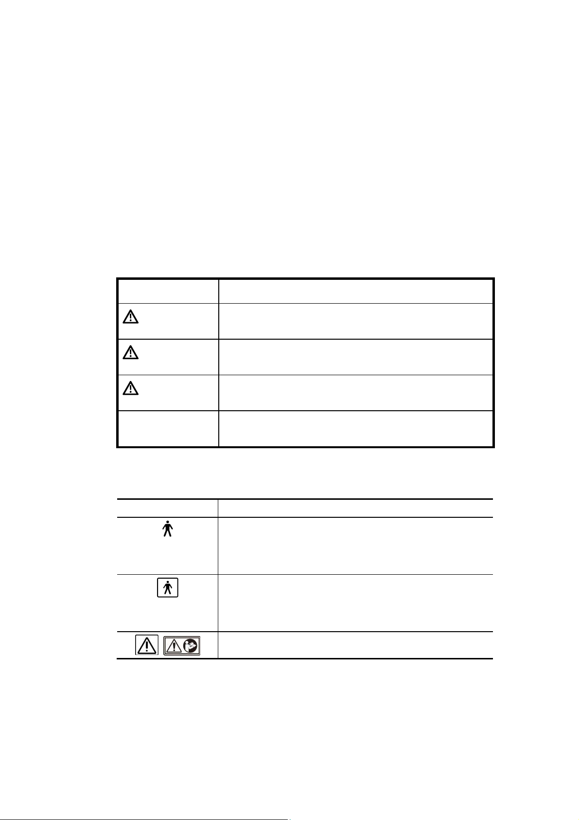
2.1 Meaning of Signal Words
In this operation manual, the signal words DANGER, WARNING, and
CAUTION are used regarding safety and other important instructions. The signal
words and their meanings are defined as follows. Please understand their meanings
clearly before reading this manual.
Signal word Meaning
DANGER
WARNING
CAUTION
CAUTION Indicates a potentially hazardous situation which, if not
Indicates an imminently hazardous situation which, if not
avoided, will result in death or serious injury.
Indicates a potentially hazardous situation which, if not
avoided, could result in death or serious injury.
Indicates a potentially hazardous situation which, if not
avoided, may result in minor or moderate injury.
avoided, may result in property damage.
2.2 Meaning of Safety Symbols
Symbol Description
Type-B applied part
* Type B when Type-B applied parts are connected.
The heart sound sensor and pulse wave sensor that can
be connected to this system are Type-B applied parts.
Type-BF applied part
* Type BF when Type-BF applied part is connected.
The reference signal cables that can be connected to this
system are Type-BF applied parts.
«Attention» (Refer to the operation manual.)
No. 2B771-004EN*M
2-1

2.3 Ensuring the Safety of Patients and Operators
Observe the following safety precautions to ensure the safety of patients and operators.
DANGER: This system must be used only when the potential benefits to
the patient are judged outweigh the possible risk to the
patient.
WARNING: 1. Do not use damaged or defective transducers. Doing so
may result in injury to the patient.
2. Take special precautions when examining a patient with
high temperature. A high patient temperature may slow
down cooling of the transducer surface, which may result
in a burn injury to the patient.
If the surface temperature of the transducer becomes
abnormally high, stop using the transducer and contact
your TOSHIBA service representative.
3. This device is contraindicated for ophthalmic use or any
application that causes the acoustic beam to pass
through the eye.
4. Do not look inside the DVD/CD unit. The emitted laser
beam is hazardous to the eyes and other parts of the
body.
5. Prolonged and repeated use of keyboards can result in
hand or arm nerve disorders in some individuals.
Observe the local institutional work safety/health
regulations on keyboard use.
6. Do not use the Fusion function (option) for patients who
use electronic life-support devices (for example, a cardiac
pacemaker or defibrillator). The magnetic field generated
in Fusion mode may affect such devices.
CAUTION: 1. Do not use the transducer on the same region of the patient
for a prolonged period. Low temperature burns may occur.
Use the transducer for the minimum period of time that is
required for diagnosis. Though the transducer surface
temperature may exceed the patient’s body temperature
under some ambient conditions and usage modes, the use
of the transducer for normal ultrasound diagnosis is unlikely
to cause low temperature burns.
2. Do not sit on the system. Doing so may result in the system
moving unexpectedly, causing you to lose your balance and
fall.
3. When this system is used to examine an elderly patient or an
infant, an attendant should be present if required.
No. 2B771-004EN*M
2-2

2.4 Preventing Electric Shocks, Fires, and Power Supply
Interruptions
Observe the following safety precautions to prevent electric shocks, fires, and power
supply interruptions.
DANGER: Never use flammable or explosive gases near this system.
Also do not use the system with oxygen or in an oxygenenriched atmosphere. Doing so may result in an explosion
(the system is not explosion-proof).
WARNING: 1. Follow the instructions below regarding the power cable
and plug.
Insert the power plug only into a 3-pin (with protective
grounding) medical electrical outlet.
Do not connect the power cable to a 2-pin outlet using
an adapter.
Do not forcibly bend the cable.
Do not modify the power cable or plug.
Do not damage the power cable or plug.
Do not twist the power cable or plug.
Do not bundle the power cable or plug.
Do not place heavy objects on the power cable or plug.
Do not pinch the power cable or plug.
Do not subject the power cable or plug to impact.
Do not pull the power cable to disconnect the plug
from the outlet.
2. If any abnormalities (such as damage or wear) are found
on the power cable or plug, the power cable and plug
must be replaced. Stop using it immediately and contact
your Toshiba service representative. Continuing to use
the system may result in electric shock, fire, or
interruption of power supply.
3. Do not use the system if the connection to the outlet is
loose.
4. If an abnormal smell or noise, or smoke occurs,
immediately turn the main power switch on the power
panel OFF and disconnect the plug from the power outlet.
Continuing to use the system with such an abnormality
may result in a fire etc. When using the system, ensure
that there is enough space for access to the main power
switch.
5. Do not allow this system or other equipment to come into
contact with the patient. If this system or other
equipment is defective, the patient may receive an electric
shock.
No. 2B771-004EN*M
2-3
WARNING: 6. Do not connect any devices other than those specified by
TOSHIBA to the USB connector or other connectors on
the system.
7. Do not connect to the system transducers other than
those specified by TOSHIBA, to prevent accidents such
as fire.
8. Do not use a defective transducer.
9. Do not remove the covers or panels of the system. Doing
so exposes high-voltage parts.
10. When in the patient environment, the operator must not
touch any exposed connectors. In addition, if the system
covers have been removed for some reason, the operator
must be extremely careful not to touch any part where the
voltage exceeds 25 VAC or 60 VDC and the patient at the
same time. Doing so may result in an electric shock.
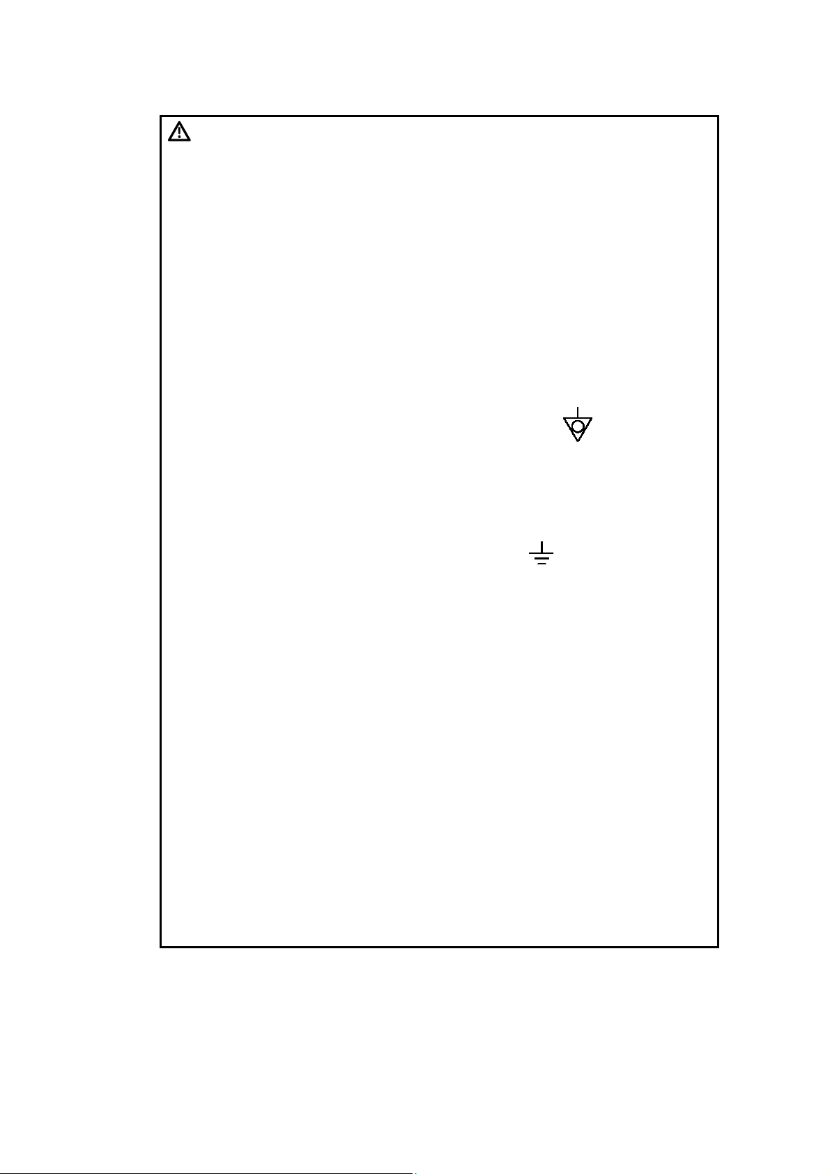
11. Connect the equipotential terminal ( ) of this system to
the equipotential bus of the facility using an equipotential
conductor. When this system is used close to a device
that is applied directly to the patient heart (such as in a
cardiac catheterization room, CCU, or ICU), voltage
equalization with the device is required to prevent an
electric shock to the patient.
12. A functional ground terminal ( ) is used to connect a
functional grounding wire between systems or between
the system and the ground for functional purposes of the
system (for example, to eliminate potential differences in
the signal level between systems or to eliminate potential
differences between the system and the ground). Do not
use the functional ground terminal for protective
grounding. Also, do not connect the functional ground
terminal to a gas pipe or water pipe. Doing so may result
in the failure of functional grounding or in a gas
explosion.
13. Use a separate socket with an appropriate rated capacity
for the supply of power to this system.
14. Do not connect this system to an outlet that shares a
circuit breaker (or fuse) with an outlet to which a device
such as a life-support system is connected. If this
system malfunctions and generates an overcurrent, or if
there is a current surge when the power is turned ON, the
circuit breaker may trip (or the fuse may blow).
15. Do not connect the diagnostic ultrasound system to the
same power outlet as another device. Doing so may
cause the circuit breaker of the facility to trip, fuses to
blow, or a fire or electric shock to occur.
No. 2B771-004EN*M
2-4
WARNING: 16. Remove the ECG electrodes from the patient before using
devices such as electric scalpels, high-frequency therapy
equipment, electrostimulators, or electric defibrillators.
In addition, when using such devices, do not let
ultrasound transducers, PCG microphones, or pulse wave
sensors to come into contact with the patient. Doing so
may result in the patient receiving a burn injury or an
electric shock.
CAUTION: 1. To prevent electric shock, do not connect peripheral units
(such as a video printer or video recording unit) to an
external outlet. Peripheral units should be connected inside
the system. For the connection procedures, contact your
TOSHIBA service representative.
2. If any abnormality of the system is found as a result of
inspection, stop using the system and contact your
TOSHIBA service representative for repair.
3. Do not spill or spray liquids such as water onto the system
or peripheral units.
2.5 Chemical Hazard
Observe the following instruction in order to protect patients and operators from
inflammation or poisoning by chemical substances.
WARNING: Handling the cord on this product will expose you to lead, a
chemical known to the State of California to cause birth
defects or other reproductive harm.
Wash hands after handling.
2.6 Electromagnetic Compatibility (EMC)
Definition: Electromagnetic compatibility (EMC) refers to the ability to function without
causing electromagnetic interference (EMI) in other devices or systems, as
well as to a certain level of immunity to EMI from other devices or systems.
Observe the following precautions to ensure EMC.
WARNING: The use of transducers and cables other than those
specified, with the exception of transducers and cables sold
by Toshiba Medical Systems Corporation as replacement
parts, may result in increased emissions or reduced system
performance.
No. 2B771-004EN*M
2-5

CAUTION: Malfunctions due to radio waves
(1) This system may malfunction due to electromagnetic
influence from electric scalpels, high-frequency therapy
equipment, or other devices that generate high
frequencies.
(2) The use of radio-wave-emitting devices near this unit may
interfere with its operation. Devices that generate radio
waves, such as cellular phones, transceivers, and radiocontrolled toys, must not be brought into the room where
this unit is installed and must never be used near the unit.
(3) If a device that generates radio waves is brought into the
room where this unit is installed, instruct the user to turn
OFF the power of the device immediately. This is
necessary to ensure proper operation of the system.
CAUTION: 1. Do not use this system in locations exposed to strong electric or
magnetic fields (near transformers, for example). Such fields may
adversely affect the monitor.
2. Do not use this system near devices that generate high frequencies
(such as medical telemeters and cordless telephones). Doing so may
cause the system to malfunction or to adversely affect such devices.
3. Do not use devices that generate high frequencies near other devices
or stack such devices on each other. If doing so is unavoidable,
confirm that the system operates normally at its usual operating
location.
2.7 Acoustic Power
Observe the following safety precautions.
CAUTION: 1. When a fetus is to be exposed to ultrasound, set the
acoustic power to as low a level as possible.
2. The FDA allows ultrasound equipment to output acoustic
power level TRACK3, which is higher than TRACK1,
provided that MI/TI values are displayed on the system.
This means that users now have a higher degree of
responsibility for safety. Users are thus required to
understand the bioeffects of ultrasound and their causes,
and to only then increase diagnostic capabilities by
increasing MI/TI.
Refer to section 24 «Using MI/TI» for details.
No. 2B771-004EN*M
2-6

2.8 Preventing System Malfunctions
Observe the following precautions to prevent system malfunctions.
CAUTION: 1. Only software authorized by TOSHIBA should be installed in
this system. Otherwise, a system failure or malfunction may
result.
2. If the system is infected with malware (malicious software,
such as a computer virus or worm), data stored in the
system may be deleted, altered, or disclosed or the system
may malfunction or infect other systems. The user must
establish security measures to prevent the system from
being infected.
(a) Do not connect this system to a network for which any
of the conditions below is true:
Security control is not established for the network.
There is a risk of malware invasion in the network.
A system for which any of the following conditions is
true is connected to or can be connected to the
network:
<1> The security of the system is not controlled by
the user.
<2> The system can be accessed by persons not
authorized by the user.
<3> The system is capable of wireless
communication.
(b) The following instructions must be observed in order to
prevent this system from being infected with malware:
Do not connect this system to the Internet.
When external storage media (such as a CD or USB
flash drive) is to be used, confirm in advance that the
media is not infected with malware.
Do not perform any other actions that may result in
infection.
No. 2B771-004EN*M
2-7

CAUTION: 1. To prevent damage to the system, do not install it in a location where
it may be exposed to the following:
Direct sunlight
Sudden temperature fluctuations
Excessive dust
Excessive shock or vibration
High temperatures
High humidity
Poor air circulation because the system air filter is blocked by a wall
etc. (A space at least 10 cm wide and 20 cm deep is required.)
2. Do not disconnect the power plug while the system is starting up.
Doing so may cause the system to malfunction.
3. If either of the following phenomena occurs, press and hold down
for 5 seconds or more to turn OFF the power of the system.
The startup screen is not displayed after waiting for 30 seconds.
The patient registration screen is not displayed after waiting for
10 minutes.
If the power is not turned ON after holding down for 5 seconds
or more, turn OFF the main power on the power panel.
Do not turn OFF the power in this manner during normal operation.
Doing so may cause the system to malfunction.
4. Do not press or use force on the main panel. Doing so may damage
the system.
5. The service outlets on the main unit provide power for recommended
external options only. Do not connect other devices to these outlets.
Doing so may result in the outlet power capacity being exceeded and
cause a system malfunction.
6. The cooling fan must be cleaned at least once a year. If the cooling
fan is clogged, the internal temperature will rise, shortening the
service life of the system. For inspection and cleaning by service
personnel, contact your TOSHIBA service representative.
7. If the main power switch on the power panel or circuit protector trips,
be sure to consult your TOSHIBA service representative. If the main
power switch is turned ON again before the problem is corrected, the
system or a connected device may sustain further damage.
No. 2B771-004EN*M
2-8

2.9 Handling Patient and Image Data
To prevent incorrect diagnosis and reexaminations, observe the following precautions
when handling data.
CAUTION: 1. Entering patient data
Before starting an examination for a new patient, confirm
that the patient ID matches the patient to be examined. If
images are recorded with an incorrect patient ID, the data
may be mixed up with that for another patient, resulting in
incorrect diagnosis.
2. This system is provided with a lossy data compression
function for images. Although this function helps to reduce
the size of stored images, it can cause image deterioration.
The amount of compression must therefore be limited so
that the image quality is maintained at a level that does not
adversely affect image reading.
2.10 Warning Labels
Various warning labels are attached to this system in order to call the user’s attention to
potential hazards.
* The symbol
use the same signal words as used in the descriptions in the operation manuals.
Read the operation manuals carefully before using the system.
The appearance and location of each warning label are as follows.
on the warning labels indicates safety precautions. Warning labels
No. 2B771-004EN*M
2-9
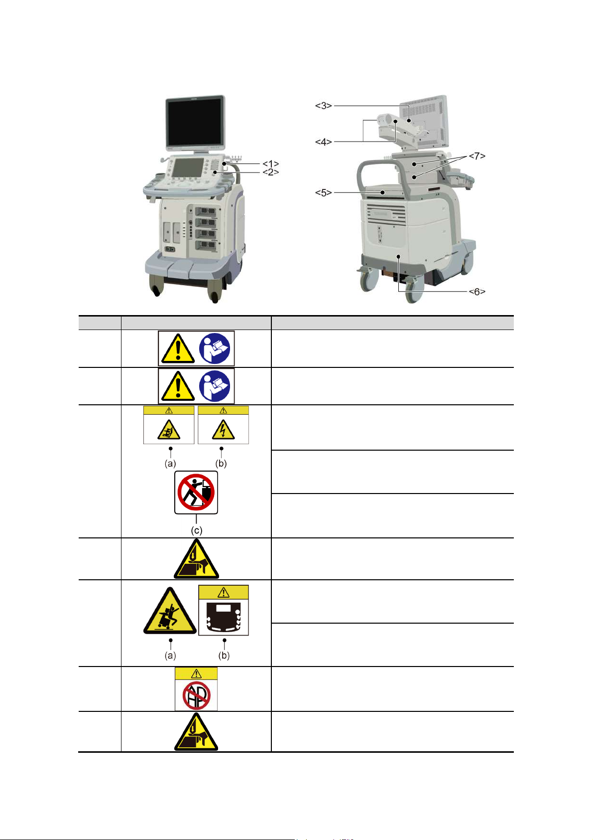
Warning labels on systems complying with the European Directive 93/42/EEC
No. Label Meaning
<1>
<2>
<3>
<4>
<5>
Urges caution related to handling of the transducers.
For handling of the transducers, refer to the
transducers’ operation manual.
Cautions that the MI/TI must be controlled as low as
reasonably achievable.
(a) Cautions that the system must be placed on a
horizontal surface.
(b) Cautions that the cover must not be removed in
order to prevent electric shock.
(c) Cautions that the system must not be leaned on
nor pushed from the side.
Cautions regarding handling of the monitor arm.
(a) Cautions against sitting on the system.
<6>
<7>
(b) Urges caution related to the switches on the
main panel.
Cautions that the system must not be used around
flammable gases.
Cautions that hands may be caught when the height
of the main panel is adjusted.
No. 2B771-004EN*M
2-10
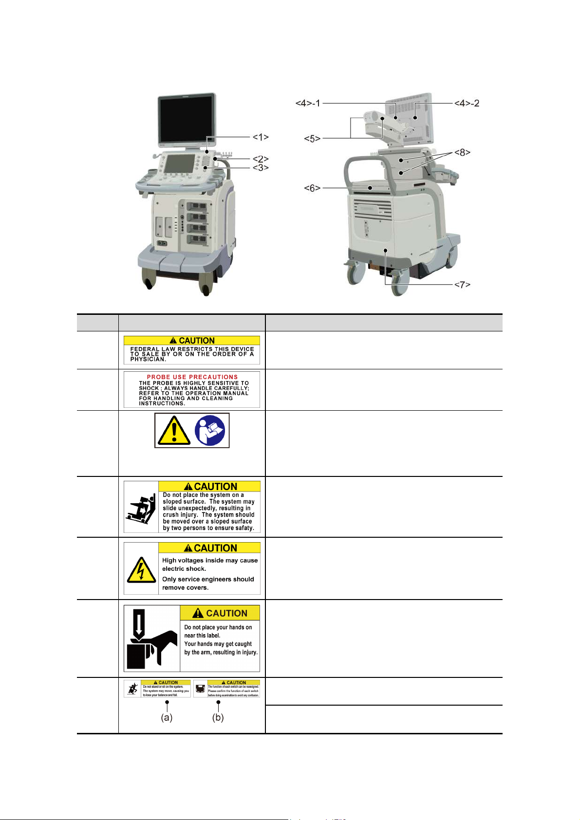
Warning labels on other systems
No. Label Meaning
<1> Cautions that restrict this device to sale by or on the
order of a physician. (USA/Canada only)
<2> Urges caution related to handling of the transducers.
<3>
<4>-1 Cautions that the system must be placed on a
<4>-2 Cautions that the cover must not be removed in
(a) Cautions that the MI/TI must be controlled as
low as reasonably achievable.
(b) As in the USA and Canada, cautions that
displayed MI/TI are mean values. Refer to
subsection 24.2.2 «MI/TI display description».
horizontal surface.
order to prevent electric shock.
<5> Cautions regarding handling of the monitor arm.
<6> (a) Cautions against sitting or leaning on the
system.
(b) Urges caution related to the switches on the
main panel.
No. 2B771-004EN*M
2-11
No. Label Meaning
<7> Cautions that the system must not be used around
flammable gases.
<8> Cautions that hands may be caught when the height
of the main panel is adjusted.
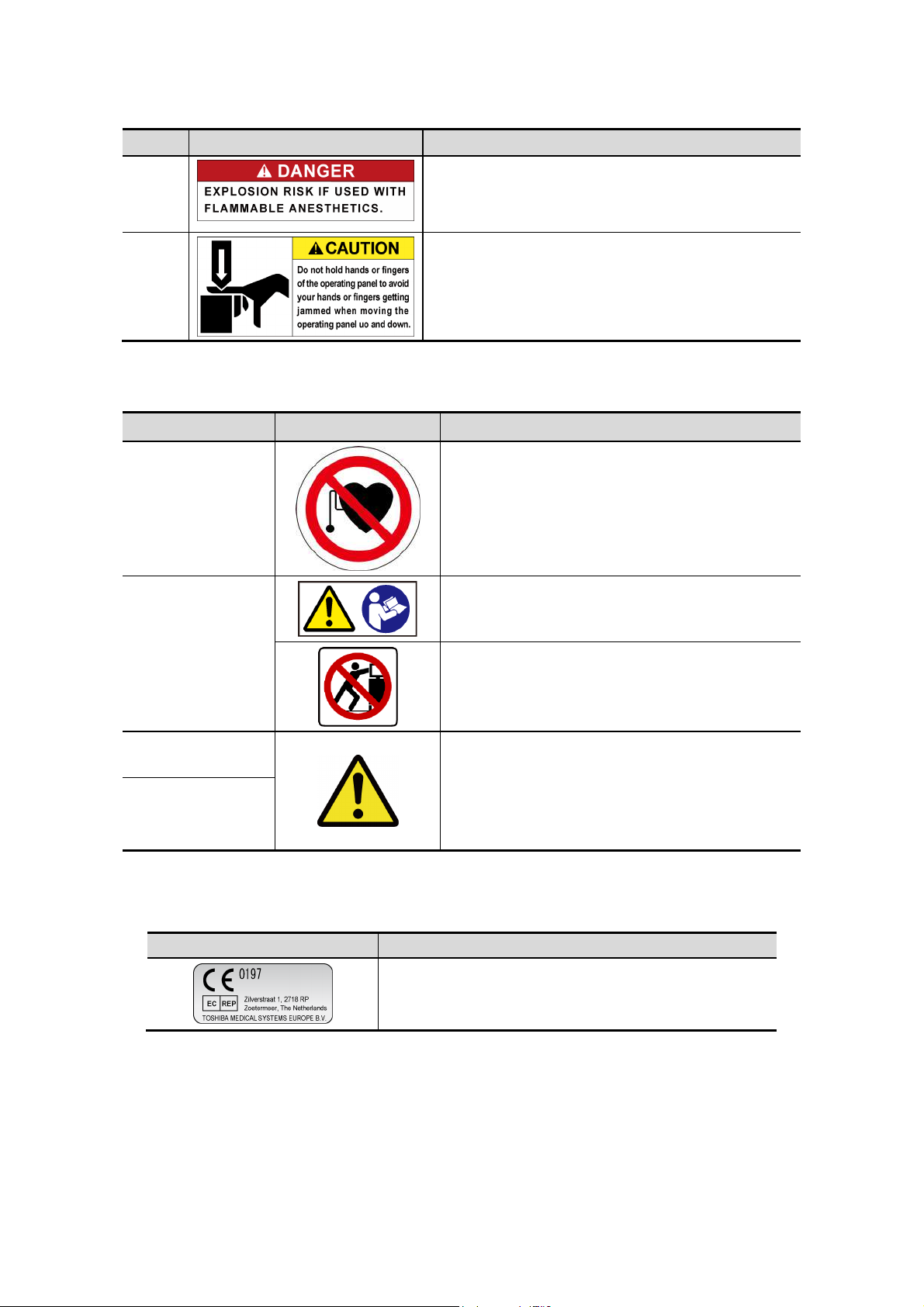
<<Warning labels for options>>
Item Label Meaning
Cautions that the Fusion function (option) must
not be used for patients who use electronic life-
Fusion unit
(UIFR-A500A)
Fusion Pole Cart
(UZWT-A500A)
support devices (for example, a cardiac
pacemaker or defibrillator). The magnetic field
generated in Fusion mode may affect such
devices.
Cautions that the operation manual must be
referred to.
Cautions that the Fusion pole cart must not be
leaned on or pushed forcefully from the side.
M-TEE hanger kit
(UAEH-770A)
Motor drive
M-TEE hanger kit
(UAEH-002A)
2.11 Regulatory Labels
Label Meaning
Precautions related to handling
1. Place the transducer in the box for
transportation.
This label indicates this device complies with European
Directive 93/42/EEC and subsequent amendments.
2. Do not allow the transducer to bump against
the main unit.
No. 2B771-004EN*M
2-12

2.12 Precautions Concerning Clinical Examination Techniques
(1) This operation manual is intended for users who are well-versed in the principles
and basic techniques of ultrasound.
(2) This system must be used only by medical personnel fully trained in clinical
examination techniques.
(3) This operation manual does not describe clinical examination techniques.
Selection of the proper clinical examination technique must be based on
specialized training and clinical experience.
No. 2B771-004EN*M
2-13
*

3. General Information on Usage
and Maintenance
1. The responsibility for maintenance and management of the product after delivery
resides with the customer who has purchased the product.
2. The warranty does not cover the following items, even during the warranty period:
(1) Damage or loss due to misuse or abuse.
(2) Damage or loss caused by Acts of God such as fires, earthquakes, floods,
lightning, etc.
(3) Damage or loss caused by failure to meet the specified conditions for this
system, such as inadequate power supply, improper installation, or
unacceptable environmental conditions.
(4) Damage or loss due to mobile use in a vehicle which is not authorized by
TOSHIBA.
(5) Damage or loss due to use outside the territory in which the system was
originally sold.
(6) Damage or loss involving system purchased from a source other than
TOSHIBA or its authorized distributors or agents.
3. This system shall not be used by persons other than fully qualified and certified
medical personnel.
4. Do not make changes or modifications to the software or hardware of this product.
5. In no event shall TOSHIBA be liable for problems, damage, or loss caused by
relocation, modification, or repair performed by personnel other than those
designated by TOSHIBA.
6. The purpose of this system is to provide physicians with data for clinical diagnosis.
The responsibility for diagnostic procedures lies with the physicians involved.
TOSHIBA shall not be liable for the results of diagnostic procedures.
7. Important data must be backed up on external recording media such as clinical
records, notebooks, floppy disks, or magnetic tapes.
8. TOSHIBA shall not be liable for loss of data stored in the memory of this system
caused by operator error or accidents.
9. This manual contains warnings regarding foreseeable potential dangers. Be alert
at all times to dangers other than those indicated.
10. TOSHIBA shall not be liable for damage or loss that results from negligence or
from ignoring the precautions and operating instructions contained in this operation
manual.
11. Ultrasound transducers are precision equipment and should be handled with
proper care. If they are not handled according to the instructions in the operation
manual, problems such as scratches, holes, defects in the acoustic lens surface,
twisting of the transducer cable, or degradation of the ultrasound images may
result.
Note that the warranty does not cover problems caused by improper handling of
the transducers.
No. 2B771-004EN*M
3-1
12. TOSHIBA shall not be liable for any error or malfunction that results from use of a
transducer other than that specified by TOSHIBA.
13. On the occasion of change of the administrator or manager for this system, be sure
to hand over this operation manual.
14. When this system is to be transported, be sure to contact your TOSHIBA service
representative first. Special packaging must be performed by a TOSHIBA service
engineer or a service engineer authorized by TOSHIBA. TOSHIBA does not
assume any responsibility for damage resulting from transportation of this system
without consulting TOSHIBA.
15. When disposing of this system, contact your TOSHIBA service representative. Do
not dispose of this system without consulting TOSHIBA service representative first.
TOSHIBA does not assume any responsibility for damage resulting from disposal
of this system without consulting TOSHIBA.
NOTE: Concerning the WEEE label
The following information is only for EU member states:
The use of this symbol indicates that this product
should not be treated as household waste.
By ensuring that this product is disposed of correctly,
you will help prevent potential negative consequences
for the environment and human health, which could
otherwise be caused by inappropriate waste-handling
of this product.
For more detailed information concerning the return
and recycling of this product, please consult the
supplier from whom you purchased the product.
* For system products, this label may be attached to the main unit only.
NOTE: Concerning BATTERIES
The following information is only for EEA countries:
The directive 2006/66/EC requires separate collection
and appropriate disposal of spent batteries.
This product also contains batteries that are not
intended to be replaced by the user.
Replacement of those batteries will usually be done
during regular maintenance or service by service staff
who can also arrange proper disposal.
NOTE: Regulatory information
The high-efficiency LCD backlights used in this product contain 5 mg or
less of mercury, the disposal of which may be regulated due to
environmental considerations.
For disposal or recycling information, please contact your local authorities
or the Electronic Industries Alliance (www.eiae.org).
This information is only for the USA.
No. 2B771-004EN*M
3-2
Loading…
Toshiba Aplio 500 TUS-A500 user guide recommended for: PAL32000, Verifier Pro T, MAMMOMAT Novation DR, Hemi Sling NC15999, FLOW.
The Toshiba Aplio 500 TUS-A500 Medical Equipment manual (Toshiba Operation manual, 232 pages) is completely safe to download (last scan date: 17/09/2024). You can rest assured of your safety when interacting with Toshiba Aplio 500 TUS-A500 document.
1
CARESCAPE Monitor B850
Technical manual PDF Manual (@96T79V), GE CARESCAPE Monitor B850 Medical Equipment (24/09/2024)
172
774
124
2
Maestra
Manual PDF User Manual (@4O12BM), Kinetec Maestra Medical Equipment (08th Sep 2024)
20
414
71
3
839 E
Manual 839 E (Exercise Bike ePDF User Guide, #7AHIV5)
32
1040
229
4
Breathe Easy
Quick start Breathe Easy Quick start — YT3918
2
279
65
5
M2 Basic
Instruction manual #8ES19G: M2 Basic Blood Pressure Monitor Instruction manual
22
255
62
6
PARAPODIUM PD150
16
612
129
8
DAC UNIVERSAL
46
1480
341
9
Provox Flush
Manual Provox Flush Manual — 3UGC38
40
1447
319
10
X-431 PADII
Manual X-431 PADII (Diagnostic Equipment ePDF Manual, #4QE164)
92
431
65

Класс прибора: экспертный Состояние: отличное Монитор: ЖК 19 дюймов Управление аппаратом: на английском языке Количество портов для подключения датчиков:
Режимы и открытые опции:
Доплеры:
Датчики:
Инструкция: на русском языке Страна производства: Япония Регистрационное удостоверение: действующее Гарантия: 12 месяцев Окончательная стоимость зависит от выбранных Вами датчиков Под заказ (1-2 недели) можем привезти любые другие датчики Нет в наличии Так же советуем посмотреть |
Универсальный ультразвуковой сканер японского бренда для экспертной диагностики. Аппарат уходит с рынка и предлагается по очень выгодной цене.
Описание прибора
Обновленная версия легендарного УЗ-сканера. Стационарный аппарат экспертного класса Aplio 500 Toshiba NEW, визуализирует анатомические структуры в высоком разрешении. Модель позволяет выявить микрокальцификаты, новообразования, нарушения в работе сердца, сосудов и мышц. Присутствует функция виртуальной эндоскопии, 4D-сканирования, эластометрии тканей, УЗИ с контрастированием. За повышение качества изображения отвечают технологии ApliPure и Superb Microvascular Imaging. Первая задействует возможности пространственного и частотного кодирования, формирует цельный визуальный ряд с сохранением клинических маркеров. Вторая улучшает отображение микрососудистого русла, используя доплеровский эффект. Модель оснащена 21-дюймовым монитором, имеет 4 активных порта. Возможно подключение педиатрических, интраоперационных, лапароскопических и чреспищеводных датчиков.
Сканер снят с производства. Интересует аппарат с похожими характеристиками? Получите консультацию у нашего специалиста, позвонив по бесплатному номеру 8 (800) 100-52-10 или закажите обратный звонок.
Характеристики
| Монитор | 21″ |
| Сенсорная панель управления | 10,4″ |
| Вес | 145 кг |
| Гарантия (мес) | 12 |
| Активные порты | 4 |
| Паркинговые порты | 2 |
| Аккумуляторная батарея | Да |
| Встроенный Wi-Fi | Да |
| Максимальная глубина сканирования | 40 см |
| Высокоплотные датчики | Да |
| Монокристальные датчики | Да |
| Матричные 1.5D датчики | Да |
| CW доплер | CW |
| Тканевой доплер | Да |
| Анатомический М-режим | FLEX-M |
| Режим визуализации микрокровотока | SMI |
| 3D Freehand | Smart 3D |
| 3D/4D | Mecha 4D |
| Виртуальный источник освещения для получения 3D/4D изображения высокой четкости (по типу HDLive GE) | Luminace |
| Объемная динамическая визуализация сердца плода STIC | STC |
| Автоматическое измерение ТВП плода в режиме 2D | Auto NT |
| Панорамное сканирование | Panoramic |
| Эластография компрессионная | Elastography |
| Эластография сдвиговая (эластометрия) | Shear wave |
| Контрасты | CHI |
| Совмещение изображений КТ/МРТ с УЗИ изображением в реальном времени | Smart Fusion |
| Магнитная навигация иглы | Smart Navigation |
| Режим «подсветки» биопсийной иглы | Beam |
| Автоматическое измерение комплекса интима-медиа | Да |
| Оценка глобальной и локальной сократимости ЛЖ сердца в 2D | 2D Wall Motion Tracking |
| Автоматические измерения в кардиологии — фракция выброса, объемы и пр. | Да |
| Стресс эхокардиография | Stress Echo |
| Педиатрические датчики | Да |
| Интраоперационные датчики | Да |
| Лапароскопические датчики | Да |
| Чреспищеводные датчики для взрослых | Да |
| Чреспищеводные датчики для детей | Да |
Инновационные технологии
- Fly Thru. Виртуальная эндосонография обеспечивает построение трехмерной модели полостей, протоков и сосудов в рельном времени, облегчает организацию инвазивных процедур и динамических исследований. Посредством Fly Thru можно установить шунты и стенты, проводить точные оперативные вмешательства.
- MicroPure. Высокотехнологичное решение в области выявления микрокальцификатов – маркеров новообразований злокачественного типа. Маркеры идентифицируются путем изучения затененных изображений целевого участка. Микрокальцификаты отображаются в виде белых пятен.
- D-THI. Режим дифференцированной тканевой гармоники, повышающий качество визуализации глубоко расположенных тканей. Получаемое изображение отличается высокой четкостью, не содержит дефектов в виде «заснеженных» и размытых участков.
- SMI. Опция, упрощающая визуализацию микроциркуляторного русла. С ее помощью обследуются сосуды с низкой интенсивностью кровотока, изучаются наиболее тонкие структуры. SMI упрощает диагностику новообразований, минимизирует вероятность ошибки.
Примеры эхограмм
Canon Toshiba Aplio 500
Примеры эхограмм Canon Toshiba Aplio 500
Датчики
Конвексные
Линейные
")
Линейный датчик Canon PLT-604AT (10L4)
4-9,2 МГц | 38 мм
Исследования поверхностных органов, сосуды, костно-мышечная система.
")
Линейный датчик Canon PLT-705BT (11L3)
3-11 МГц | 45 мм
Исследования поверхностных органов, сосуды, костно-мышечная система.
")
Линейный датчик Canon PLT-1005BT (14L5)
4-14 МГц | 58 мм
Исследования поверхностных органов, сосуды, костно-мышечная система.
")
Линейный датчик Canon PLT-1204BT (18L7)
5-18 МГц | 38 мм
Исследования поверхностных органов, сосуды, костно-мышечная система.
")
Линейный датчик Canon PLT-1204BX (18LX7)
5-18 МГц | 38 мм
Исследования поверхностных органов, сосуды, костно-мышечная система.
Внутриполостные
Микроконвексные
")
Микроконвексный датчик Canon PVT-382BT (6MC1)
1,5-5,5 МГц
Неонатология и педиатрия: абдоминальные исследования, почки, сердце, глубоко расположенные сосуды, мозг, суставы.
")
Микроконвексный датчик Canon PVT-712BT (11MC4)
3,3-11 МГц
Неонатология и педиатрия: абдоминальные исследования, почки, сердце, глубоко расположенные сосуды, мозг, суставы.
3D/4D объемные
Биплановые
Интраоперационные
")
Интраоперационный линейный датчик Canon PLT-1202S (14L7)
6-18 МГц | 25 мм
Скелетно-мышечная система, интраоперационные исследования, подкожные структуры, периферические сосуды.
")
Интраоперационный линейный датчик Canon PLT-705BTF (11LI4)
3,8-11 МГц
Интраоперационные исследования, абдоминальные структуры.
")
Интраоперационный конвексный датчик Canon PVT-745BTV (11CI4)
3,8-11 МГц
Интраоперационные исследования, абдоминальные структуры.
")
Интраоперационный конвексный датчик Canon PVT-745BTF (11CI4)
3,8-11 МГц
Интраоперационные исследования, абдоминальные структуры.
")
Интраоперационный конвексный датчик Canon PVT-745BTH (11CI4)
3,8-11 МГц
Интраоперационные исследования, абдоминальные структуры.
")
Интраоперационный линейный датчик Canon PLT-705BTH (11LI4)
3,8-11 МГц
Интраоперационные исследования, абдоминальные структуры.
")
Интраоперационный линейный датчик Canon PLT-1202BT (17LH7)
6-17 МГц
Скелетно-мышечная система, интраоперационные исследования, подкожные структуры, периферические сосуды.
Чреспищеводные
Лапароскопические
Секторные
")
Секторный датчик Canon PST-25BT (5S1)
1,8-4,2 МГц
Кардиология, транскраниальные и абдоминальные исследования.
")
Секторный датчик Canon PST-30BT (5S2)
1,8-4,8 МГц
Кардиология, транскраниальные и абдоминальные исследования.
")
Секторный датчик Canon PST-50BT (6S3)
2,8-6,2 МГц
Кардиология, транскраниальные исследования, абдоминальные исследования, педиатрия.
")
Секторный датчик Canon PST-65AT (9S4)
4-9 МГц
Кардиология, транскраниальные исследования, абдоминальные исследования, педиатрия.
Похожие товары
Аналогичные или близкие по возможностям к Canon Toshiba Aplio 500 УЗИ сканеры, которые вам подойдут.
Калькулятор лизинга
Стоимость оборудования
900 000 руб.
900 000 руб. 7 000 000 руб.
Авансовый платеж
180 000 руб./20%
10% 50%
Срок
12
12 месяцев 60 месяцев
руб/мес.
Вопросы и ответы
Нужна помощь?
Задайте свой вопрос по данному оборудованию, и вам ответит product-специалист, инженер по медицинскому оборудованию или специалист отдела продаж.
Задать вопрос
Проконсультируйтесь с экспертом:
Запросите всю интересующую вас информацию по данному оборудованию.
Страна производства: Япония
Производитель: Canon Toshiba
Год выпуска: 2022
Гарантия: 12 месяцев
Класс: эксперт
Тип: стационарный
Состояние: Новый
Наличие: Снят с производства
Калькулятор
лизинга
Описание прибора
Характеристики
Инновационные технологии
Примеры эхограмм
Датчики
Похожие товары
Вопросы и ответы
Гарантируем лучшую цену
Официальный поставщик в России
Бесплатная апробация в клинике от 7 дней
Бесплатная доставка в любую точку РФ
Бесплатный монтаж, пуско-наладка и обучение врачей
Получить коммерческое предложение
Заполните форму и мы вышлем вам коммерческое предложение,
составленное согласно потребностям врачей в течение 10-ти минут.
Toshiba Aplio 500 TUS-A500 Operation manual
- Toshiba
- Medical Equipment
- Operation manual for Toshiba Aplio 500 TUS-A500
- toshiba-aplio-500-tus-a500-operation-manual-232_manual.pdf
- 232 |
Pages Preview:
Document Transcription:
See Details
Download