
-
Руководства по ремонту
1
-
Инструкции по эксплуатации
6
Языки:
SONY STR-DE445 инструкция по эксплуатации
(170 страниц)
- Языки:Польский, Русский
-
Тип:
PDF -
Размер:
1.9 MB -
Описание:
Ресивер
Просмотр
SONY STR-DE445 инструкция по эксплуатации
(56 страниц)
- Языки:Английский
-
Тип:
PDF -
Размер:
1.78 MB
Просмотр
SONY STR-DE445 инструкция по эксплуатации
(226 страниц)
- Языки:Английский, Итальянский, Немецкий, Португальский
-
Тип:
PDF -
Размер:
2.48 MB
Просмотр
SONY STR-DE445 инструкция по эксплуатации
(161 страница)
- Языки:Испанский, Китайский, Французский
-
Тип:
PDF -
Размер:
1.93 MB
Просмотр
SONY STR-DE445 инструкция по эксплуатации
(226 страниц)
- Языки:Нидерландский, Шведский
-
Тип:
PDF -
Размер:
2.47 MB
Просмотр
SONY STR-DE445 инструкция по эксплуатации
(114 страниц)
- Языки:Датский, Финский
-
Тип:
PDF -
Размер:
1.21 MB
Просмотр
На NoDevice можно скачать инструкцию по эксплуатации для SONY STR-DE445. Руководство пользователя необходимо для ознакомления с правилами установки и эксплуатации SONY STR-DE445. Инструкции по использованию помогут правильно настроить SONY STR-DE445, исправить ошибки и выявить неполадки.
Раздел: Видео Аудио Фото Оборудование
Тип: Ресивер
Инструкция к Ресиверу Sony STR-DE445

4-227-987-74(1)
FM Stereo
FM-AM Receiver
GB
Operating Instructions
RU
Инструкция по эксплуатации
PL
Instrukcja obsługi
STR-DE545
STR-DE445
STR-SE501
2000 Sony Corporation

WARNING
Precautions
To prevent fire or shock
On safety
Should any solid object or liquid fall into
hazard, do not expose the
the cabinet, unplug the receiver and have it
unit to rain or moisture.
checked by qualified personnel before
operating it any further.
To avoid electrical shock,
do not open the cabinet.
On power sources
• Before operating the receiver, check that
Refer servicing to qualified
the operating voltage is identical with
personnel only.
your local power supply. The operating
voltage is indicated on the nameplate at
Do not install the
the rear of the receiver.
appliance in a confined
• The unit is not disconnected from the AC
power source (mains) as long as it is
space, such as a bookcase
connected to the wall outlet, even if the
or built-in cabinet.
unit itself has been turned off.
• If you are not going to use the receiver
for a long time, be sure to disconnect the
receiver from the wall outlet. To
disconnect the AC power cord, grasp the
plug itself; never pull the cord.
• AC power cord must be changed only at
the qualified service shop.
On placement
• Place the receiver in a location with
adequate ventilation to prevent heat
buildup and prolong the life of the
receiver.
• Do not place the receiver near heat
sources, or in a place subject to direct
sunlight, excessive dust or mechanical
shock.
• Do not place anything on top of the
cabinet that might block the ventilation
holes and cause malfunctions.
On operation
Before connecting other components, be
sure to turn off and unplug the receiver.
On cleaning
Clean the cabinet, panel and controls with
a soft cloth slightly moistened with a mild
detergent solution. Do not use any type of
abrasive pad, scouring powder or solvent
such as alcohol or benzine.
If you have any question or problem
concerning your receiver, please
consult your nearest Sony dealer.
GB
2

About This Manual
TABLE OF CONTENTS
The instructions in this manual are for the STR-DE545,
STR-DE445 and STR-SE501. Check your model number by
Hooking Up the Components 4
looking at the upper right corner of the front panel or
lower right corner of the remote. In this manual, the STR-
Unpacking 4
DE545 and the remote commander RM-U304 are used for
Antenna Hookups 5
illustration purposes unless stated otherwise. Any
Audio Component Hookups 6
difference in operation is clearly indicated in the text, for
example, “STR-DE545 only”.
Video Component Hookups 7
Digital Component Hookups 8
Type of differences
5.1CH Input Hookups 9
Other Hookups 10
Model
DE545
DE445 SE501
Feature
CONTROL A1-II
Hooking Up and Setting Up the
•
•
SPEAKERS FRONT B
•
•
Speaker System 12
S-Video
•
•
Speaker System Hookup 13
TV/SAT OPTICAL IN
Performing Initial Setup Operations 15
•
•
AC OUTLET
Multi Channel Surround Setup 16
•
•
Before You Use Your Receiver 20
Conventions
• The instructions in this manual describe the controls on
Location of Parts and Basic
the receiver. You can also use the controls on the
supplied remote if they have the same or similar names
Operations 22
as those on the receiver. For details on the use of the
remote RM-PP404 (STR-DE545 and STR-SE501 only),
Front Panel Parts Descriptions 22
refer to the separate operating instructions supplied
with the remote.
• The following icon is used in this manual:
Enjoying Surround Sound 27
z Indicates hints and tips for making the task easier.
Selecting a Sound Field 28
This receiver incorporates Dolby* Digital and Pro Logic
Understanding the Multi-Channel Surround Displays
31
Surround and the DTS** Digital Surround System.
Customizing Sound Fields 33
Manufactured under license from Dolby Laboratories.
*
“Dolby”, “AC-3”, “Pro Logic” and the double-D symbol a are
trademarks of Dolby Laboratories.
Receiving Broadcasts 37
Manufactured under license from Digital Theater Systems, Inc. US
**
Storing FM Stations Automatically 39
Pat. No. 5,451,942 and other worldwide patents issued and pending.
Direct Tuning 39
“DTS” and “DTS Digital Surround” are trademarks of Digital
Theater Systems, Inc. © 1996 Digital Theater Systems, Inc. All
Automatic Tuning 40
rights reserved.
Preset Tuning 40
Using the Radio Data System (RDS) 41
Demonstration Mode
The demonstration will activate the first time you turn on the
power. When the demonstration starts, the following message
Other Operations 44
appears in the display :
“NOW DEMONSTRATION MODE IF YOU FINISH
Naming Preset Stations and Program Sources 45
DEMONSTRATION PLEASE PRESS POWER KEY
Recording 45
WHILE THIS MESSAGE APPEARS IN THE DISPLAY
THANK YOU”
Using the Sleep Timer 46
To cancel the demonstration
Adjustment Using the SET UP Button 47
Press 1/u to turn the receiver off while the above message is
being displayed. The next time you turn the receiver on, the
demonstration will not appear.
Additional Information 48
To view the demonstration
Troubleshooting 48
Hold down SET UP and press 1/u to turn on the power.
Specifications 50
Notes
• Running the demonstration will clear the receiver’s
Glossary 52
memory. For details on what will be cleared, see “Clearing
Settings Using SUR, LEVEL, BASS/TREBLE, and
the receiver’s memory” on page 15.
SET UP buttons 53
• There will be no sound when the demonstration mode is
activated.
Remote Button Descriptions (STR-DE445 only) 54
Index 57
GB
3
Hooking Up
Unpacking
the
Check that you received the following items with the
receiver:
• FM wire antenna (1)
Components
• AM loop antenna (1)
• R6 (size-AA) batteries (2)
• STR-DE545 and STR-SE501 only
• Remote Commander RM-PP404 (remote) (1)
This chapter describes how to connect
• Operating instructions of the remote (1)
• Operating instructions of CONTROL A1 II (1)
various audio and video components
• STR-DE445 only
to the receiver. Be sure to read the
• Remote Commander RM-U304 (remote) (1)
sections for the components you have
before you actually connect them to
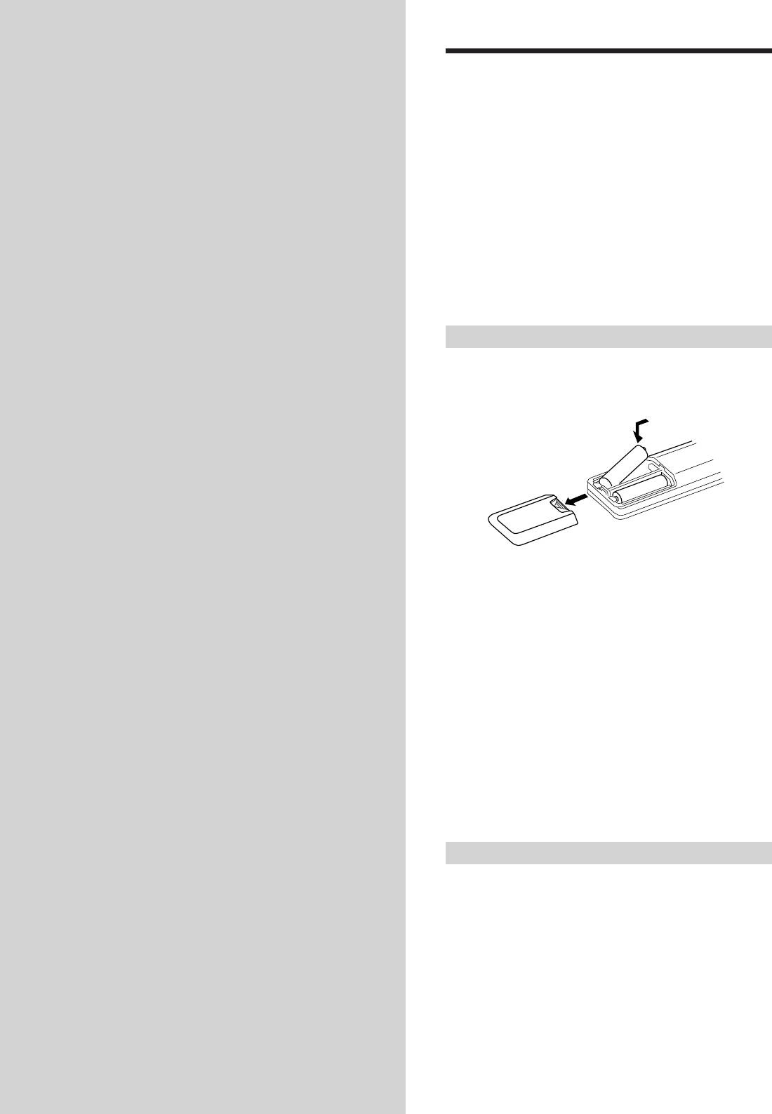
Inserting batteries into the remote
the receiver.
Insert R6 (size-AA) batteries with the + and – properly
oriented in the battery compartment. When using the
remote, point it at the remote sensor g on the receiver.
]
}
}
]
For details, refer to the operating instructions supplied
with your remote (STR-DE545 and STR-SE501 only).
z
When to replace batteries
Under normal conditions, the batteries should last for about 6
months. When the remote no longer operates the receiver, replace
all batteries with new ones.
Notes
• Do not leave the remote in an extremely hot or humid place.
• Do not use a new battery with an old one.
• Do not expose the remote sensor to direct sunlight or lighting
apparatuses. Doing so may cause a malfunction.
• If you don’t use the remote for an extended period of time,
remove the batteries to avoid possible damage from battery
leakage and corrosion.
Before you get started
• Turn off the power to all components before making
any connections.
• Do not connect the AC power cords until all of the
connections are completed.
• Be sure to make connections firmly to avoid hum and
noise.
• When connecting an audio/video cord, be sure to
match the color-coded pins to the appropriate jacks on
the components: yellow (video) to yellow; white (left,
audio) to white; and red (right, audio) to red.
GB
4
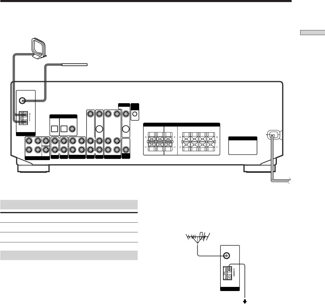
Antenna Hookups
AM loop antenna
Hooking Up the Components
(supplied)
FM wire antenna
(supplied)
FM
75Ω
COAXIAL
MONITOR
CTRL
A1 I I
DIGITAL IN
TV/SAT
DVD/LD
VIDEO IN
VIDEO IN
VIDEO OUT VIDEO IN VIDEO OUT
AM
SPEAKERS
REAR
CENTER B FRONT A
RL
RLRL
ANTENNA
OPTICAL OPTICAL COAXIAL
S-VIDEO
S-VIDEO
IN
OUT
L
L
L
L
L
AC OUTLET
AUDIO
FRONT
SWITCHED 120W/1A MAX
OUT
4 Ω 8 ΩCENTER
R
SUB
AUDIO IN AUDIO IN
R
R
RLRL
WOOFER
REC OUT IN AUDIO IN
R
R
AUDIO OUT AUDIO IN
RL
AC 120V 60Hz
FRONT REAR
AUDIO IN
SUB
IMPEDANCE
5.1 CH INPUT
AUX CD
MD/TAPE
TV/SAT
DVD/LD
VIDEO
WOOFER
SELECTOR
z
If you have poor FM reception
Terminals for connecting the antennas
Use a 75-ohm coaxial cable (not supplied) to connect the receiver
to an outdoor FM antenna as shown below.
Connect the To the
AM loop antenna AM terminals
Outdoor FM antenna
FM wire antenna FM 75Ω COAXIAL terminal
Notes on antenna hookups
• To prevent noise pickup, keep the AM loop antenna
Ground wire
away from the receiver and other components.
(not supplied)
• Be sure to fully extend the FM wire antenna.
• After connecting the FM wire antenna, keep it as
horizontal as possible.
To ground
Important
If you connect the receiver to an outdoor antenna, ground
it against lightning. To prevent a gas explosion, do not
connect the ground wire to a gas pipe.
GB
5
FM
75Ω
COAXIAL
AM
ANTENNA
Receiver
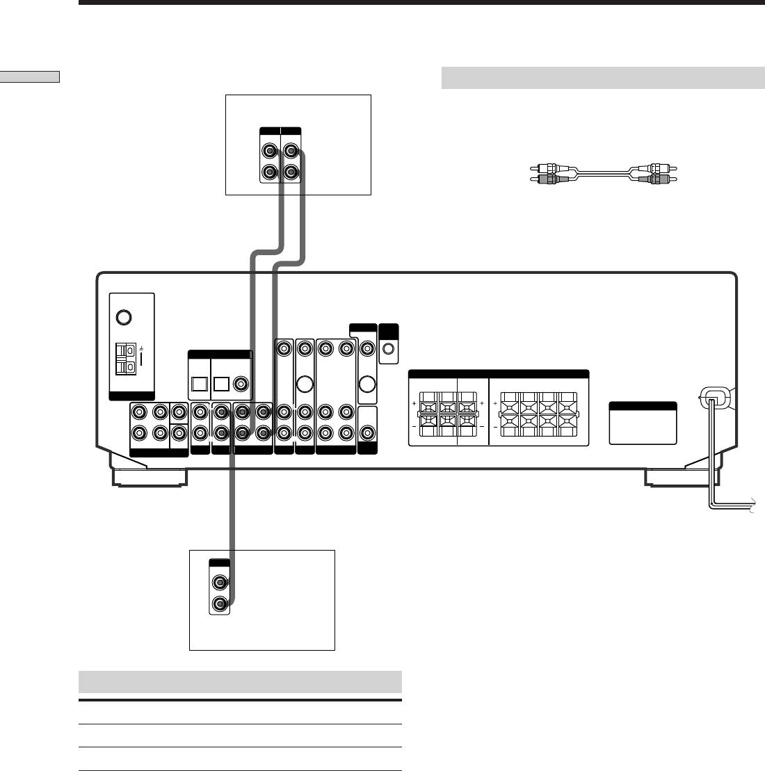
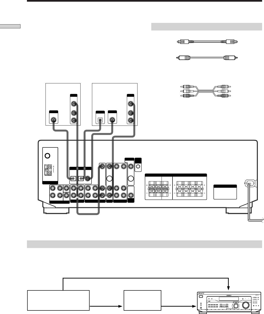
Audio Component Hookups
Required cords
Hooking Up the Components
Audio cords (not supplied)
MD/TAPE deck
When connecting a cord, be sure to match the color-coded pins to
the appropriate jacks on the components.
White (L) White (L)
Red (R) Red (R)
CD player
Jacks for connecting audio components
Connect a To the
CD player CD jacks
MD deck or Tape deck MD/TAPE jacks
GB
6
INPUT OUTPUT
LINELINE
L
R
IN OUT
ç
ç
FM
75Ω
COAXIAL
MONITOR
CTRL
A1 I I
DIGITAL IN
TV/SAT
DVD/LD
VIDEO IN
VIDEO IN
VIDEO OUT VIDEO IN VIDEO OUT
AM
SPEAKERS
REAR
CENTER B FRONT A
RL
RLRL
ANTENNA
OPTICAL OPTICAL COAXIAL
S-VIDEO
S-VIDEO
IN
OUT
L
L
L
L
L
AC OUTLET
AUDIO
FRONT
OUT
4 Ω 8 ΩCENTER
R
FRONT REAR
WOOFER
SUB
AUDIO IN AUDIO IN
R
REC OUT IN AUDIO IN
R
R
AUDIO IN
AUDIO OUT AUDIO IN
R
RL
RLRL
SUB
IMPEDANCE
5.1 CH INPUT
AUX CD
MD/TAPE
TV/SAT
DVD/LD
VIDEO
WOOFER
SELECTOR
OUTPUT
LINE
L
R
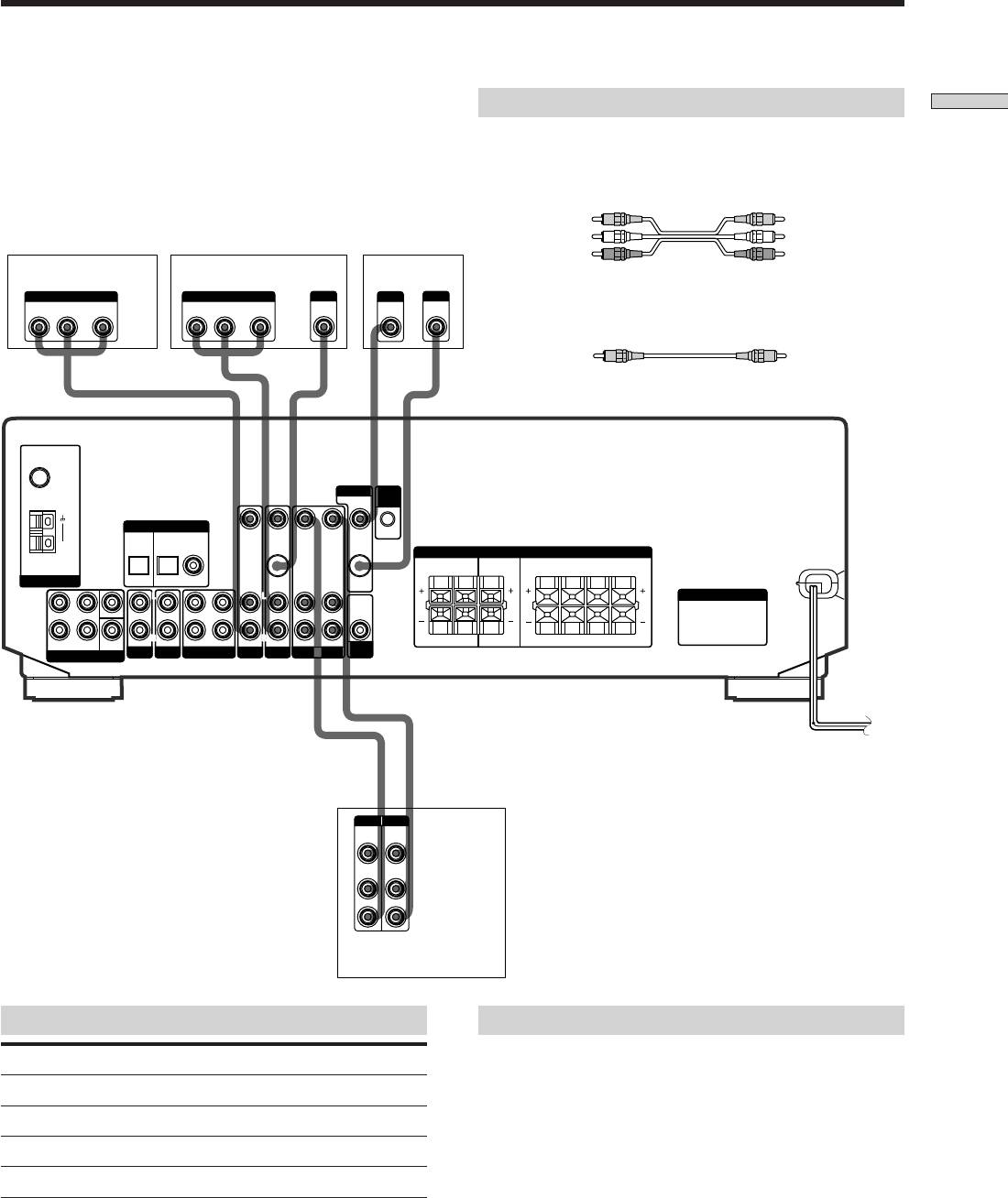
Video Component Hookups
Required cords
Hooking Up the Components
Audio/video cords (not supplied)
When connecting a cord, be sure to match the color-coded pins to
the appropriate jacks on the components.
Yellow (video) Yellow (video)
White (L/audio) White (L/audio)
TV or Satellite tuner
DVD or LD player
TV monitor
Red (R/audio) Red (R/audio)
OUTPUT
OUTPUT
S-VIDEO
INPUT
S-VIDEO
AUDIO OUT VIDEO
AUDIO OUT VIDEO
OUT
VIDEO
IN
IN
RL
OUT
RL
OUT
Video cord for connecting a TV monitor (not supplied)
Yellow Yellow
FM
75Ω
COAXIAL
MONITOR
CTRL
A1 I I
DIGITAL IN
TV/SAT
DVD/LD
VIDEO IN
VIDEO IN
VIDEO OUT VIDEO IN VIDEO OUT
AM
SPEAKERS
REAR
CENTER B FRONT A
RL
RLRL
ANTENNA
OPTICAL OPTICAL COAXIAL
S-VIDEO
S-VIDEO
IN
OUT
L
L
L
L
L
AC OUTLET
AUDIO
FRONT
OUT
4 Ω 8 ΩCENTER
R
R
R
R
R
RL
RLRL
FRONT REAR
WOOFER
SUB
AUDIO IN AUDIO IN
REC OUT IN AUDIO IN
AUDIO IN
AUDIO OUT AUDIO IN
SUB
IMPEDANCE
5.1 CH INPUT
AUX CD
MD/TAPE
TV/SAT
DVD/LD
VIDEO
WOOFER
SELECTOR
ç
ç
IN OUT
INPUT OUTPUT
VIDEO
VIDEO
IN
OUT
AUDIO
AUDIO
IN
OUT
L
R
VCR
Jacks for connecting video components
Note on video component hookups
You can connect your TV’s audio output jacks to the TV/
Connect a To the
SAT AUDIO IN jacks on the receiver and apply sound
TV or Satellite tuner TV/SAT jacks
effects to the audio from the TV. In this case, do not
VCR VIDEO jacks
connect the TV’s video output jack to the TV/SAT VIDEO
IN jack on the receiver. If you are connecting a separate
DVD or LD player DVD/LD jacks
TV tuner (or satellite tuner), connect both the audio and
TV monitor MONITOR VIDEO OUT jack
video output jacks to the receiver as shown above.
z
When using the S-video jacks instead of the video jacks
(STR-DE545 and STR-SE501 only)
Your monitor must also be connected via an S-video jack. S-video
signals are on a separate bus from the video signals and will not
be output through the video jacks.
GB
7
Digital Component Hookups
Connect the digital output jacks of your DVD player and
Required cords
Hooking Up the Components
satellite tuner (etc.) to the receiver’s digital input jacks to
Optical digital cords (not supplied)
bring the multi channel surround sound of a movie
theater into your home. To enjoy full effect of multi
Black Black
channel surround sound, five speakers (two front
Coaxial digital cord (not supplied)
speakers, two rear speakers, and a center speaker) and a
Yellow Yellow
sub woofer are required. You can also connect an LD
player with an RF OUT jack via an RF demodulator, such
Audio/video cords (not supplied)
as the Sony MOD-RF1 (not supplied).
When connecting a cord, be sure to match the color-coded pins to
the appropriate jacks on the components.
Yellow (video) Yellow (video)
TV or Satellite
DVD player (etc.)*
White (L/audio) White (L/audio)
tuner
OUTPUT
OUTPUT
VIDEO
VIDEO
OUT
OUT
Red (R/audio) Red (R/audio)
AUDIO
AUDIO
OUT
OUT
**
Note
OUTPUT
OUTPUT
OUTPUT
DIGITAL
L
DIGITAL
DIGITAL
OPTICAL
The optical and coaxial digital input jacks on the receiver are
OPTICAL
COAXIAL
R
compatible with sampling frequencies of 32 kHz, 44.1 kHz, and
48 kHz.
FM
75Ω
COAXIAL
MONITOR
CTRL
A1 I I
DIGITAL IN
TV/SAT
DVD/LD
VIDEO IN
VIDEO IN
VIDEO OUT VIDEO IN VIDEO OUT
AM
**
SPEAKERS
REAR
CENTER B FRONT A
RL
RLR
L
ANTENNA
OPTICAL OPTICAL COAXIAL
S-VIDEO
S-VIDEO
IN
OUT
L
L
L
L
L
AC OUTLET
AUDIO
FRONT
SWITCHED 120W/1A MAXSWITCHED 120W/1A MAX
OUT
4 Ω 8 ΩCENTER
R
AC 120V 60HzAC 120V 60Hz
FRONT REAR
SUB
AUDIO IN AUDIO IN
R
WOOFER
REC OUT IN AUDIO IN
R
R
AUDIO IN
AUDIO OUT AUDIO IN
R
RL
RLRL
SUB
IMPEDANCE
5.1 CH INPUT
AUX CD
MD/TAPE
TV/SAT
DVD/LD
VIDEO
WOOFER
SELECTOR
* When making digital audio connections to a DVD player, connect to either the coaxial OR optical digital jacks, and not
both. It is recommended to make digital audio connections to the coaxial jack.
** STR-DE545 and STR-SE501 only.
Example of LD player connected via an RF demodulator
Please note that you cannot connect an LD player’s AC-3 RF OUT jack directly to the receiver’s digital input jacks. You
must first convert the RF signal to either an optical or coaxial digital signal. Connect the LD player to the RF demodulator,
then connect the RF demodulator’s optical or coaxial digital output to the receiver’s OPTICAL or COAXIAL DVD/LD IN
jack. Refer to the instruction manual supplied with your RF Demodulator for details on AC-3 RF hookups.
DVD/LD
VIDEO OUT
VIDEO IN
DIGITAL
DIGITAL
DVD/LD IN
DVD/LD IN
MULTI CHANNEL DECODING
? / 1
DIMMER
– PTY SELECT +
PRESET/
DISPLAY
SHIFT
AC-3 RF
(COAXIAL)
(COAXIAL)
BASS BOOST TONE
– TUNING +
MEMORY
R ON r OFF
SPEAKERS
INPUT MODE
MASTER VOLUME
FM/AM
FM MODE
OUT
RF demodulatorLD player
or (OPTICAL)
(OPTICAL)
A
I
i
RDS EON RDS PTY
B
VIDEO
DVD/LD TV/SAT
5.1CH INPUT
A B C
CINEMA STUDIO
LEVEL
–
+
SET UP
PHONES
MD/TAPE CD TUNER AUX
SOUND FIELD
MUTING
SUR
BOOST
BASS
TONE
A. F. D.
2CH MODE
NAME
TREBLE
BASS/
ENTER
Note
When making connections as shown above, be sure to set INPUT MODE (3 on page 23) manually. The receiver may not operate correctly
if INPUT MODE is set to “AUTO.”
GB
8
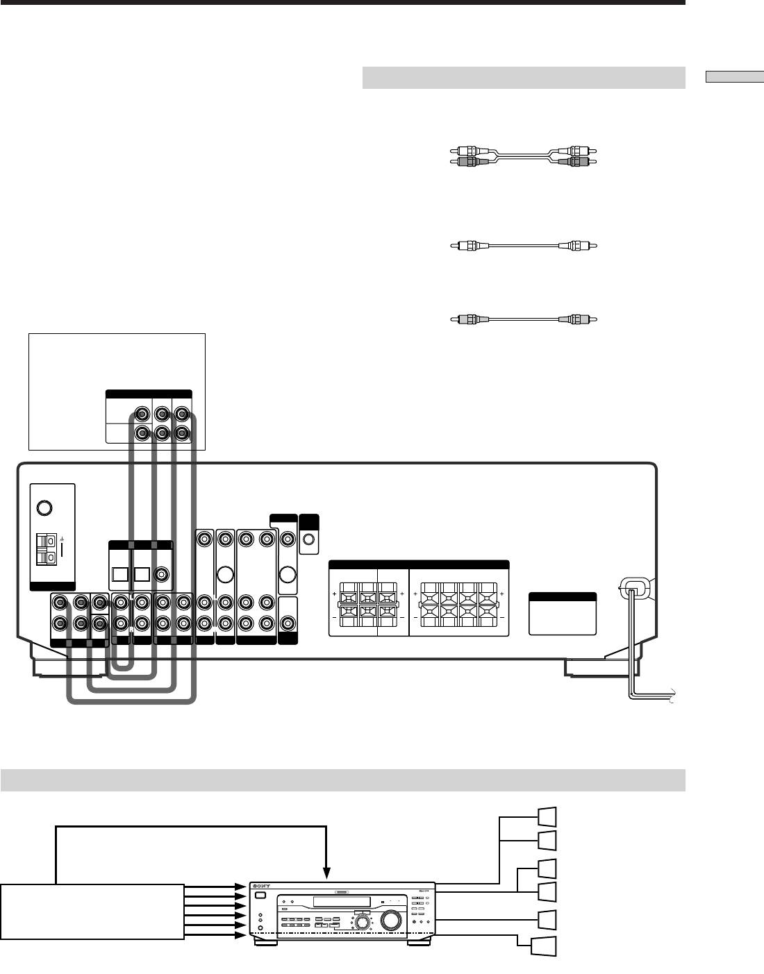
5.1CH Input Hookups
Although this receiver incorporates a multi channel
Required cords
Hooking Up the Components
decoder, it is also equipped with 5.1CH INPUT jacks.
Audio cords (not supplied)
These connections allow you to enjoy multichannel
Two for the 5.1CH INPUT FRONT and REAR jacks
software encoded in formats other than Dolby Digital
(AC-3) and DTS. If your DVD player is equipped with
White (L) White (L)
5.1CH OUTPUT jacks, you can connect them directly to
Red (R) Red (R)
the receiver to enjoy the sound of the DVD player’s multi
channel decoder. Alternatively, the 5.1CH INPUT jacks
Monaural audio cords (not supplied)
can be used to connect an external multi channel decoder.
Two for the 5.1CH INPUT CENTER and SUB WOOFER jacks
To fully enjoy multi channel surround sound, you will
need five speakers (two front speakers, two rear speakers,
Black Black
and a center speaker) and a subwoofer. Refer to the
instruction manual supplied with your DVD player, multi
Video cord (not supplied)
channel decoder, etc., for details on the 5.1 channel input
One for the DVD/LD VIDEO IN jacks (etc.)
hookups.
Yellow Yellow
DVD player,
Note
Multichannel decoder, etc.
When using the connections described below, adjust the level of
your surround speakers and subwoofer from the DVD player or
5.1 CH OUTPUT
multichannel decoder.
REAR
FRONT
CENTER
WOOFER
FM
75Ω
COAXIAL
MONITOR
CTRL
A1 I I
DIGITAL IN
TV/SAT
DVD/LD
VIDEO IN
VIDEO IN
VIDEO OUT VIDEO IN VIDEO OUT
AM
SPEAKERS
REAR
CENTER B FRONT A
RL
RLRL
ANTENNA
OPTICAL OPTICAL COAXIAL
S-VIDEO
S-VIDEO
IN
OUT
L
L
L
L
L
AC OUTLET
AUDIO
FRONT
OUT
4 Ω 8 ΩCENTER
R
SUB
AUDIO IN AUDIO IN
R
REC OUT IN AUDIO IN
R
R
FRONT REAR
WOOFER
AUDIO IN
AUDIO OUT AUDIO IN
R
RL
RLRL
SUB
IMPEDANCE
5.1 CH INPUT
AUX CD
MD/TAPE
TV/SAT
DVD/LD
VIDEO
WOOFER
SELECTOR
Example of a DVD player hookup using the 5.1CH INPUT jacks
Front Speaker (L)
Front Speaker (R)
DVD/LD
VIDEO IN etc.
SPEAKERS
Rear Speaker (L)
VIDEO OUT
5.1 CH INPUT
FRONT
MULTI CHANNEL DECODING
? / 1
DIMMER
DISPLAY
– PTY SELECT +
PRESET/
SHIFT
Rear Speaker (R)
BASS BOOST TONE
– TUNING +
MEMORY
SPEAKERS
SPEAKERS
MASTER VOLUME
FM/AM
FM MODE
DVD player
R ON r OFF
A
INPUT MODE
I
i
RDS EON RDS PTY
B
VIDEO
DVD/LD TV/SAT
5.1CH INPUT
A B C
CINEMA STUDIO
LEVEL
–
+
SET UP
MD/TAPE CD TUNER AUX
SOUND FIELD
MUTING
SUR
NAME
BOOST
BASS
TONE
REAR/CENTER
PHONES
Center Speaker
A. F. D.
2CH MODE
TREBLE
BASS/
ENTER
SUB WOOFER
Active Woofer
Note
See page 13 for details on speaker system hookup.
GB
9
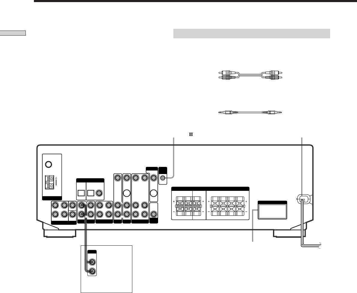
Other Hookups
Required cords
Hooking Up the Components
Audio cords (not supplied)
When connecting a cord, be sure to match the color-coded pins to the
appropriate jacks on the components.
White (L) White (L)
Red (R) Red (R)
CONTROL A1 connecting cord (not supplied) (STR-DE545 and STR-SE501
only)
Black Black
CONTROL A1
(STR- DE545 and
AC power cord
STR-SE501 only)
FM
75Ω
COAXIAL
MONITOR
CTRL
A1 I I
DIGITAL IN
TV/SAT
DVD/LD
VIDEO IN
VIDEO IN
VIDEO OUT VIDEO IN VIDEO OUT
AM
SPEAKERS
REAR
CENTER B FRONT A
RL
RLRL
ANTENNA
OPTICAL OPTICAL COAXIAL
S-VIDEO
S-VIDEO
IN
OUT
L
L
L
L
L
AC OUTLET
AUDIO
FRONT
OUT
4 Ω 8 ΩCENTER
R
SUB
AUDIO IN AUDIO IN
R
REC OUT IN AUDIO IN
R
R
AUDIO OUT AUDIO IN
R
RL
RLRL
FRONT REAR
WOOFER
AUDIO IN
SUB
IMPEDANCE
5.1 CH INPUT
AUX CD
MD/TAPE
TV/SAT
DVD/LD
VIDEO
WOOFER
SELECTOR
AC OUTLET
b
OUTPUT
To a wall outlet
LINE
CD player, tape deck,
MD deck, etc.
GB
10

CONTROL A1 hookup (STR-DE545 and
Connecting the AC power cord
Hooking Up the Components
STR-SE501 only)
Before connecting the AC power cord of this receiver to a
• If you have a CONTROL A1 compatible Sony
wall outlet:
CD player, tape deck, or MD deck
• Connect the speaker system to the receiver (see page
Use a CONTROL A1 cord (not supplied) to connect the
13).
CONTROL A1
jack on the CD player, tape deck, or
MD deck to the CONTROL A1
jack on the receiver.
Connect the AC power cord(s) of your audio/video
Refer to the separate manual “CONTROL-A1
Control
components to a wall outlet.
System” and the operating instructions supplied with
your CD player, tape deck, or MD deck for details.
STR-DE545 and STR-SE501 only
If you connect other audio/video components to the AC
Note
OUTLET(s) on the receiver, the receiver will supply power
If you make CONTROL A1 connections from the receiver to
to the connected component(s), allowing you to turn the
an MD deck that is also connected to a computer, do not
whole system on or off when you turn the receiver on or
operate the receiver while using the “Sony MD Editor”
off.
software. This may cause a malfunction.
Caution
• If you have a Sony CD changer with a
Make sure that the total power consumption of the component(s)
COMMAND MODE selector
connected to the receiver’s AC OUTLET(s) does not exceed the
If your CD changer’s COMMAND MODE selector can
wattage stated on the rear panel. Do not connect high-wattage
be set to CD 1, CD 2, or CD 3, be sure to set the
electrical home appliances such as electric irons, fans, or TVs to
command mode to “CD 1” and connect the changer to
this outlet. (STR-DE545 and STR-SE501 only)
the CD jacks on the receiver.
If, however, you have a Sony CD changer with VIDEO
Note
If the AC power cord is disconnected for about two weeks, the
OUT jacks, set the command mode to “CD 2” and
receiver’s entire memory will be cleared and the demonstration
connect the changer to the VIDEO IN jacks on the
will start.
receiver.
AUX AUDIO IN hookup
• If you have an individual audio component
(except PHONO)
Use the audio cords to connect the LINE OUT jacks on
the CD player, tape deck, or MD deck to the AUX
AUDIO IN jack on the receiver so that you can listen to
stereo sources in surround sound.
GB
11

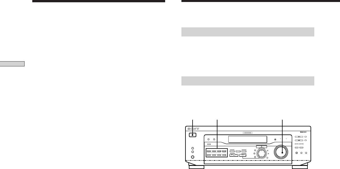
SET UP
Hooking Up
Cursor buttons
and Setting Up
MULTI CHANNEL DECODING
? / 1
– PTY SELECT +
PRESET/
SHIFT
DIMMER
DISPLAY
BASS BOOST TONE
– TUNING +
MEMORY
FM/AM
R ON r OFF
SPEAKERS
INPUT MODE
MASTER VOLUME
FM MODE
A
I
i
RDS EON RDS PTY
B
VIDEO
DVD/LD TV/SAT
5.1CH INPUT
CINEMA STUDIO
–
+
the Speaker
A B C
LEVEL
SET UP
MUTING
BOOST
BASS
TONE
PHONES
MD/TAPE CD TUNER AUX
SOUND FIELD
SUR
NAME
A. F. D.
2CH MODE
TREBLE
BASS/
ENTER
System
Jog dial
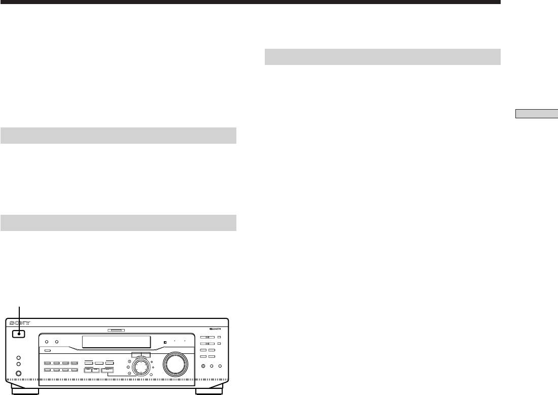
Brief descriptions of buttons and control
This chapter describes how to hook
used to set up the speaker system
up your speaker system to the
receiver, how to position each speaker,
SET UP button: Press to enter the setup mode when
and how to set up your speakers to
specifying speaker types and distances.
enjoy multi channel surround sound.
Cursor buttons ( / ): Use to select parameters after
pressing the SET UP button.
Jog dial: Use to adjust the setting of each parameter.
GB
12
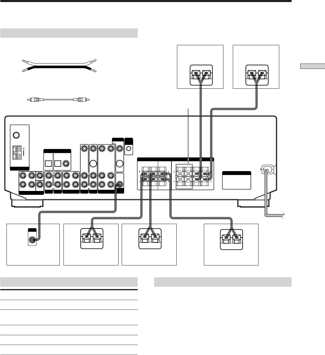
Speaker System Hookup
Required cords
Speaker cords (not supplied)
One for each front, rear, and center speaker
Front speaker (R)
Front speaker (L)
(+)
(+)
(–)
(–)
Hooking Up and Setting Up the Speaker System
}
]
}
]
Monaural audio cord (not supplied)
One for an active sub woofer
Black Black
*FRONT
SPEAKERS B
FM
75Ω
COAXIAL
MONITOR CTRL
A1 I I
DIGITAL IN
TV/SAT
DVD/LD
VIDEO IN
VIDEO IN
VIDEO OUT VIDEO IN VIDEO OUT
AM
SPEAKERS
REAR
CENTER B FRONT A
R L
R L R L
ANTENNA
OPTICAL OPTICAL COAXIAL
S-VIDEO
S-VIDEO
IN
OUT
L
L
L
L
L
AC OUTLET
AUDIO
FRONT
OUT
4 Ω 8 ΩCENTER
R
R
R
R
FRONT REAR
WOOFER
SUB
AUDIO IN AUDIO IN
REC OUT IN AUDIO IN
AUDIO IN
AUDIO OUT AUDIO IN
R
R L
R L R L
SUB
IMPEDANCE
5.1 CH INPUT
AUX CD
MD/TAPE VIDEO
DVD/LDTV/SAT
WOOFER
SELECTOR
INPUT
AUDIO
IN
}
]
}
]
}
]
Active sub woofer Rear speaker (R)
Rear speaker (L)
Center speaker
Terminals for connecting the speakers
Notes on speaker system hookup
• Twist the stripped ends of the speaker cords about 10
Connect the To the
mm (2/3 inch). Be sure to match the speaker cord to the
Front speakers (8 ohm) SPEAKERS FRONT A terminals
appropriate terminal on the components: + to + and – to
*Additional pair of front SPEAKERS FRONT B terminals
–. If the cords are reversed, the sound will be distorted
speakers (8 ohm)
and will lack bass.
• If you use front speakers with low maximum input
Rear speakers (8 ohm) SPEAKERS REAR terminals
rating, adjust the volume carefully to avoid excessive
Center speaker (8 ohm) SPEAKERS CENTER terminals
output on the speakers.
Active sub woofer SUB WOOFER AUDIO OUT jack
• You can also connect Micro Satellite Speaker (e.g.
SA-VE230) to the receiver. Micro Satellite Speaker is a
5.1 Channel speaker system consisting of two front
* STR-DE545 and STR-SE501 only.
speakers, two rear speakers, one center speaker and one
subwoofer.
GB
13
Speaker System Hookup
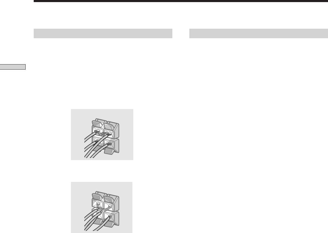
To avoid short-circuiting the speakers
To avoid damaging your speakers
Short-circuiting of the speakers may damage the receiver.
Make sure that you turn down the volume before you
To prevent this, make sure to take the following
turn off the receiver. When you turn on the receiver, the
precautions when connecting the speakers.
volume remains at the level you turn off the receiver.
Hooking Up and Setting Up the Speaker System
Make sure the stripped ends of each speaker cord
does not touch another speaker terminal or the
stripped end of another speaker cord.
Examples of poor conditions of the speaker cord
Stripped speaker cord is touching another speaker terminal.
Stripped cords are touching each other due to excessive
removal of insulation.
After connecting all the components, speakers,
and AC power cord, output a test tone to check
that all the speakers are connected correctly. For
details on outputting a test tone, see page 19.
If no sound is heard from a speaker while outputting a
test tone or a test tone is output from a speaker other than
the one whose name is currently displayed on the
receiver, the speaker may be short-circuited. If this
happens, check the speaker connection again.
GB
14
Performing Initial Setup Operations
Once you have made speaker connections and have
Setting up the receiver
turned on the power for the first time, clear the receiver’s
Before you use your receiver for the first time, use the SET
memory. After you have done this, set the speaker sizes,
UP button to adjust settings to correspond to your system.
speaker locations and other initial system settings that are
You can set the following items. For details on how to
necessary.
adjust each setting, see the page in parentheses.
• Set the speaker size (page 16).
Hooking Up and Setting Up the Speaker System
Before turning on the receiver
• Set the speaker distance (page 18).
• Select the 5.1CH INPUT video signal (page 47).
Make sure that you have:
• Selected the appropriate front speakers (see “7
SPEAKERS selector” on page 23). (STR-DE545 and
STR-SE501 only)
Clearing the receiver’s memory
Before you use your receiver for the first time or when
you want to clear the receiver’s memory, do the following.
If the Demonstration appears when the power is turned
on, this procedure is not necessary.
1/u
MULTI CHANNEL DECODING
? / 1
– PTY SELECT +
PRESET/
SHIFT
DIMMER
DISPLAY
BASS BOOST TONE
– TUNING +
MEMORY
SPEAKERS
INPUT MODE
MASTER VOLUME
FM/AM
FM MODE
R ON r OFF
A
I
i
RDS EON RDS PTY
B
VIDEO
DVD/LD TV/SAT
5.1CH INPUT
CINEMA STUDIO
LEVEL
–
+
A B C
SET UP
MUTING
BOOST
BASS
TONE
PHONES
MD/TAPE CD TUNER AUX
SOUND FIELD
SUR
NAME
A. F. D.
2CH MODE
TREBLE
BASS/
ENTER
1 Turn off the receiver.
2 Hold down ?/1 for four seconds.
The currently selected function, then the
demonstration message appears in the display and the
items including the following are reset or cleared:
• All preset stations are reset or cleared.
• All sound field parameters are reset to their factory
settings.
• All index names (of preset stations and program
sources) are cleared.
• All adjustments made with the SET UP button are
reset to their factory settings.
• The sound field memorized for each program source
and preset stations are cleared.
GB
15
Multi Channel Surround Setup
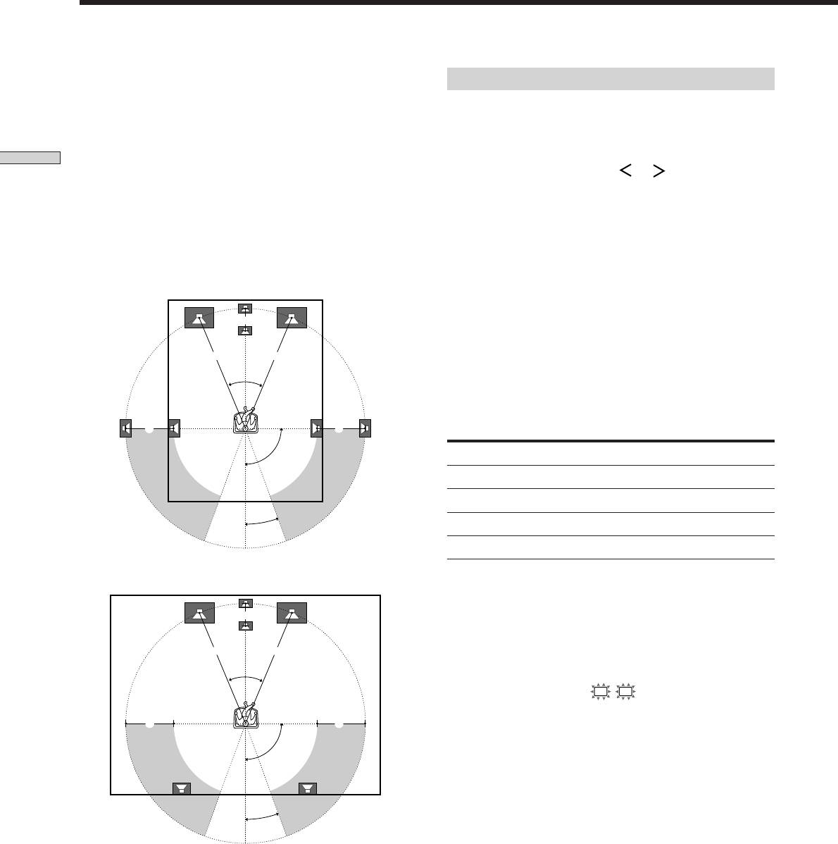
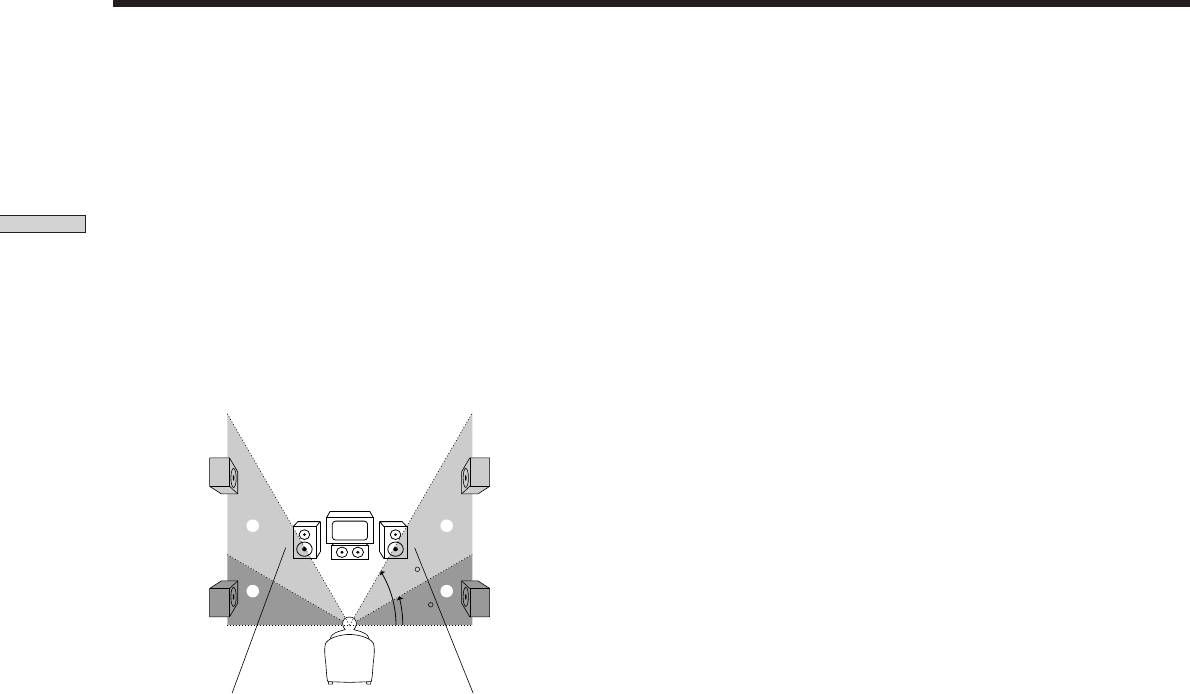
For the best possible surround sound all speakers should
Specifying the speaker parameters
be the same distance from the listening position (A).
1 Press ?/1 to turn on the receiver.
(However, this unit lets you to place the center speaker up
to 1.5 meters (5 feet) closer (B) and the rear speakers up
2 Press SET UP.
to 4.5 meters (15 feet) closer (C) to the listening position.
The front speakers can be placed from 1.0 to 12.0 meters (3
Hooking Up and Setting Up the Speaker System
3 Press the cursor buttons ( or ) to select the
to 40 feet) from the listening position (A).)
parameter you want to adjust.
You can place the rear speakers either behind you or to
4 Turn the jog dial to select the setting you want.
the side, depending on the shape of your room (etc.).
The setting is stored automatically.
When the rear speakers are placed to the side
5 Repeat steps 3 and 4 until you have set all of the
parameters that follow.
B
z
Normal speaker and Micro Satellite speaker
Choose NORM. SP if you’re using normal speakers and MICRO
A A
SP if you’re using Micro Satellite speakers. If you choose NORM.
SP, you can adjust the speaker size and the sub woofer selection
45°
as mentioned below. However, if you choose MICRO SP, the
speaker size and the sub woofer selection has been configurated
as follows:
CC
Speakers
Settings
90°
Front
SMALL
Center
SMALL
Rear
SMALL
20°
Woofer
YES
When the rear speakers are placed behind you
You cannot change the configuration if you choose MICRO SP.
B
For STR-SE501, the speaker size and sub woofer selection has
been preset to MICRO SP according to the supplied speaker
system. If you change the speaker system, choose NORM. SP to
A A
adjust the speaker size and sub woofer selection.
45°
p Front speaker size (
L
R
)
Initial setting : LARGE (STR-DE545/DE445)
CC
SMALL (STR-SE501)
• If you connect large speakers that will effectively
90°
reproduce bass frequencies, select “LARGE”. Normally,
select “LARGE”.
• If the sound is distorted, or you feel a lack of surround
effects when using multi channel surround sound,
20°
select “SMALL” to activate the bass redirection circuitry
and output the front channel bass frequencies from the
sub woofer.
Note
• When the front speaker is set to “SMALL”, the center
Do not place the center speaker farther away from the listening
and rear speakers are also automatically set to
position than the front speakers.
“SMALL” (unless previously set to “NO”).
GB
16
p Center speaker size (
C
)
z
About speaker sizes (LARGE and SMALL)
Initial setting : LARGE (STR-DE545/DE445)
Internally, the LARGE and SMALL settings for each speaker
SMALL (STR-SE501)
determine whether or not the internal sound processor will cut
the bass signal from that channel. When the bass is cut from a
• If you connect a large speaker that will effectively
channel the bass redirection circuitry sends the corresponding
reproduce bass frequencies, select “LARGE”. Normally,
bass frequencies to the sub woofer or other “LARGE” speaker.
select “LARGE”. However, if the front speakers are set
However, since bass sounds have a certain amount of
Hooking Up and Setting Up the Speaker System
to “SMALL”, you cannot set the center speaker to
directionality it best not to cut them, if possible. Therefore, even
“LARGE”.
when using small speakers, you can set them to “LARGE” if you
• If the sound is distorted, or you feel a lack of surround
want to output the bass frequencies from that speaker. On the
effects when using multi channel surround sound,
other hand, if you are using a large speaker, but prefer not to
select “SMALL” to activate the bass redirection circuitry
have bass frequencies output from that speaker, set it to
and output the center channel bass frequencies from the
“SMALL”.
1
front speakers (if set to “LARGE”) or sub woofer. *
If the overall sound level is lower than you prefer, set all speakers
• If you do not connect the center speaker, select “NO”.
to “LARGE”. If there is not enough bass, you can use the bass/
treble to boost the bass levels. To adjust the bass/treble, see page
The sound of the center channel will be output from the
2
35.
front speakers.*
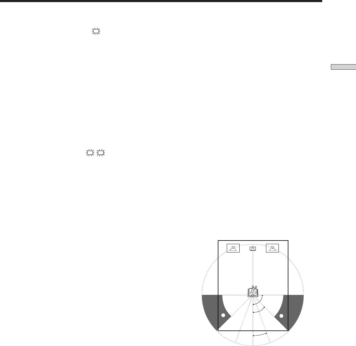
p Rear speaker position (REAR PL.)*
p Rear speaker size (
LS
RS
)
Initial setting : BEHIND
Initial setting : LARGE (STR-DE545/DE445)
This parameter lets you specify the location of your rear
SMALL (STR-SE501)
speakers for proper implementation of the Digital Cinema
• If you connect large speakers that will effectively
Sound surround modes in the “VIRTUAL” sound fields.
reproduce bass frequencies, select “LARGE”. Normally,
Refer to the illustration below.
select “LARGE”. However, if the front speakers are set
• Select “SIDE” if the location of your rear speakers
to “SMALL”, you cannot set the rear speakers to
corresponds to section A.
“LARGE”.
• Select “BEHIND” if the location of your rear speakers
• If the sound is distorted, or you feel a lack of surround
corresponds to section B.
effects when using multi channel surround sound,
This setting only effects the surround modes in the
select “SMALL” to activate the bass redirection circuitry
“VIRTUAL” sound fields.
and output the rear channel bass frequencies from the
sub woofer or other “LARGE” speakers.
3
• If you do not connect rear speakers, select “NO”.*
z
*1~*3 correspond to the following Dolby Pro Logic modes
1
*
NORMAL
2
*
PHANTOM
3
*
3 STEREO
90°
A
45°
A
B
B
20°
* These parameters are not available when “Rear speaker
size (REAR)” is set to “NO”.
GB
17
Multi Channel Surround Setup
p Rear speaker height (REAR HGT.)*
p Sub woofer selection (SUB WOOFER)
Initial setting : LOW
Initial setting : YES
This parameter lets you specify the height of your rear
• If you connect a sub woofer, select “YES”.
speakers for proper implementation of the Digital Cinema
• If you do not connect a sub woofer, select “NO”. This
Sound surround modes in the “VIRTUAL” sound fields.
activates the bass redirection circuitry and outputs the
Refer to the illustration below.
LFE signals from other speakers.
Hooking Up and Setting Up the Speaker System
• Select “LOW” if the location of your rear speakers
• In order to take full advantage of the Dolby Digital
corresponds to section A.
(AC-3) bass redirection circuitry, we recommend that
• Select “HIGH” if the location of your rear speakers
you set your sub woofer’s cut off frequency as high as
corresponds to section B.
possible.
This setting only affects the surround modes in the
“VIRTUAL” sound fields.
p Front speaker distance (FRONT)
Initial setting : 5.0 meter
Set the distance from your listening position to the front
(left or right) speaker (A on page 16).
• Front speaker distance can be set in 0.1 meter (1 foot)
steps from 1.0 to 12.0 meters (3 to 40 feet).
• If both speakers are not placed an equal distance from
B
B
your listening position, set the distance to the closest
speaker.
60
A
A
30
p Center speaker distance (CENTER)
Initial setting : 5.0 meter
Set the distance from your listening position to the center
speaker.
• Center speaker distance can be set in 0.1 meter (1 foot)
* These parameters are not available when “Rear speaker
steps from a distance equal to the front speaker distance
size (REAR)“ is set to “NO”.
(A on page 16) to a distance 1.5 meters (5 feet) closer to
your listening position (B on page 16).
z
About the rear speaker position (SIDE, and BEHIND)
• Do not place the center speaker farther away from your
This setting is designed specifically for implementation of the
listening position than the front speakers.
Digital Cinema Sound modes in the “VIRTUAL” sound fields.
With the Digital Cinema Sound modes, speaker position is not as
p Rear speaker distance (REAR)
critical as other modes. All of the modes in the “VIRTUAL”
Initial setting : 3.5 meter
sound fields were designed under the premise that the rear
Set the distance from your listening position to the rear
speaker would be located behind the listening position, but
(left or right) speaker.
presentation remains fairly consistent even with the rear speakers
• Rear speaker distance can be set in 0.1 meter (1 foot)
positioned at a rather wide angle. However, if the speakers are
steps from a distance equal to the front speaker distance
pointing toward the listener from the immediate left and right of
(A on page 16) to a distance 4.5 meters (15 feet) closer
the listening position, the “VIRTUAL” sound fields will not be
effective unless the rear speaker position parameter is set to
to your listening position (C on page 16).
“SIDE”.
• Do not place the rear speakers farther away from your
Nevertheless, each listening environment has many variables,
listening position than the front speakers.
such as wall reflections, and you may obtain better results using
• If both speakers are not placed an equal distance from
“BEHIND” if your speakers are located high above the listening
your listening position, set the distance to the closest
position, even if they are to the immediate left and right.
speaker.
Therefore, although it may result in a setting contrary to the
“Rear speaker position” explanation, we recommend that you
play back multi channel surround encoded software and listen to
the effect each setting has on your listening environment. Choose
the setting that provides a good sense of spaciousness and that
best succeeds in forming a cohesive space between the surround
sound from the rear speakers and the sound from the front
speakers. If you are not sure which sounds best, select
“BEHIND” and then use the speaker distance parameter and
speaker level adjustments to obtain proper balance.
GB
18

z
About speaker distances
Adjusting the speaker volume
This receiver allows you to input the speaker position in terms of
Use the remote while seated in your listening position to
distance. However, it is not possible to set the center speaker
farther away than the front speakers. Also, the center speaker can
adjust the volume of each speaker.
not be set more that 1.5 meters (5 feet) closer than the front
Note
speakers.
This receiver incorporates a new test tone with a frequency
Likewise, the rear speakers cannot be set farther away from the
Hooking Up and Setting Up the Speaker System
centered at 800 Hz for easier speaker volume adjustment.
listening position than the front speakers. And they can be no
more than 4.5 meters (15 feet) closer.
1 Press ?/1 to turn on the receiver.
This is because incorrect speaker placement is not conducive to
enjoy the surround sound.
2 Press TEST TONE on the supplied remote.
Please note that, setting the speaker distance closer than the
You will hear the test tone from each speaker in
actual location of the speakers will cause a delay in the output of
sequence.
the sound from that speaker. In other words, the speaker will
sound like it is farther away.
For example, setting the center speaker distance 1~2 m (3~6 feet)
3 Adjust the volume level so that the volume of the
closer than the actual speaker position will create a fairly realistic
test tone from each speaker sounds the same
sensation of being “inside” the screen. If you cannot obtain a
when you are in your main listening position.
satisfactory surround effect because the rear speakers are too
• To adjust the balance of the front right and front left
close, setting the rear speaker distance closer (shorter) than the
speakers, use the front balance parameter in the
actual distance will create a larger soundstage. (1 foot
LEVEL menu (see page 34).
corresponds to a 1 ms difference.)
• To adjust the balance of the rear right and rear left
Adjusting these parameters while listening to the sound often
speakers, use the rear balance parameter in the
results in much better surround sound. Give it a try!
LEVEL menu (see page 34).
• To adjust the volume level of the center speaker,
press MENU </> to select the center parameter.
Use +/– on the remote to adjust the level.
• To adjust the volume level of the rear speaker, press
MENU </> to select the rear parameter.
Use +/– on the remote to adjust the level.
4 Press TEST TONE on the remote again to turn off
the test tone.
Note
The test tone cannot be output when the receiver is set to 5.1CH
INPUT.
z
You can adjust the volume level of all speakers at the same
time
Rotate MASTER VOLUME on the receiver or press MASTER
VOL +/– on the remote.
GB
19
Multi Channel Surround Setup
Before You Use Your
Receiver
Notes
Before turning on the receiver
• The front balance, rear balance, center level, and rear level are
shown in the display during adjustment.
Make sure that you have:
• Although these adjustments can also be made via the front
• Selected the appropriate front speakers (see “7
panel using the LEVEL menu (when the test tone is output, the
SPEAKERS selector” on page 23). (STR-DE545 and
receiver switches to the LEVEL menu automatically), we
STR-SE501 only)
Hooking Up and Setting Up the Speaker System
recommend you follow the procedure described above and
adjust the speaker levels from your listening position using the
remote control.
Checking the connections
After connecting all of your components to the receiver,
z
When setting the volume levels for each speaker
do the following to verify that the connections were made
Let’s assume that you have matched the sound levels of all the
correctly.
speakers using the test tone. Although this lays the foundation
for high quality surround sound, it may be necessary to make
1/u
Function buttons
MASTER VOLUME
further adjustments while listening to playback of actual
software. This is because most software contains center and rear
channels recorded at slightly lower levels than the two front
MULTI CHANNEL DECODING
? / 1
– PTY SELECT +
PRESET/
SHIFT
channels.
DIMMER
DISPLAY
BASS BOOST TONE
– TUNING +
MEMORY
FM/AM
FM MODE
When you actually play back software recorded in multi channel
SPEAKERS
INPUT MODE
MASTER VOLUME
R ON r OFF
A
I
i
RDS EON RDS PTY
+
surround, you will notice that increasing the center and rear
B
VIDEO
DVD/LD TV/SAT
5.1CH INPUT
CINEMA STUDIO
–
A B C
LEVEL
SET UP
MUTING
BOOST
BASS
TONE
PHONES
MD/TAPE CD TUNER AUX
SOUND FIELD
SUR
NAME
A. F. D.
2CH MODE
speaker levels produces a better blend between the front and
TREBLE
BASS/
ENTER
center speakers and greater cohesion between the front and rear
speakers. Increasing the level of the center speaker about 1 dB,
and the rear speakers about 1~2 dB is likely to produce better
results.
1 Press ?/1 to turn on the receiver.
In other words, in order to create a more cohesive soundstage
with balanced dialog, we recommend that you make some
2 Press a function button to select a component
adjustments while playing your software. Changes of only 1 dB
(program source) that you connected (e.g., CD
can make a huge difference in the character of the soundstage.
player or tape deck).
3 Turn on the component and start playing it.
4 Rotate MASTER VOLUME to turn up the volume.
If you do not obtain normal sound output after
performing this procedure, look for the reason in the
checklist on the following page and take the appropriate
measures to correct the problem.
GB
20
Оглавление
Аннотация для Ресивера Sony STR-DE445 в формате PDF
Топ 10 инструкций
Другие инструкции
-
Страница 1
STR-DE545 STR-DE445 STR-SE501 DE ES IT 4-227-987- 54 (1) FM Ster eo FM-AM Receiver 2000 Sony Corporation PT Bedienungsanleitung Manual de instrucciones Istruzioni per l’uso Manual de instruções[…]
-
Страница 2
2 DE Zur besonder en Beachtung VORSICHT Um Feuergefahr und die Gefahr eines elektrischen Schlages zu vermeiden, darf das Gerät weder Regen noch Feuchtigkeit ausgesetzt werden. Um einen elektrischen Schlag zu vermeiden, darf das Gehäuse nicht geöffnet wer den. Überlassen Sie W artungsarbeiten stets nur einem Fachmann. Stellen Sie das Gerät nich[…]
-
Страница 3
3 DE I NHALTSVERZEICHNIS Anschluß der Geräte 4 Nach dem Auspacken 4 Antennenanschluß 5 Anschluß von Audiogeräten 6 Anschluß von V ideogeräten 7 Anschluß von Digitalgeräten 8 Anschluß an die 5.1CH-Anschlüsse 9 Sonstige Anschlüsse 10 Aufstellen der Anlage und Anschluß der Lautspr echer 12 Anschluß der Lautspr echer 13 V orber eitende Se[…]
-
Страница 4
4 DE Nach dem Auspacken V ergewissern Sie sich, da ß die folgenden T eile vorhanden sind: • UKW -Antenne (1) • MW -Rahmenantenne (1) • R6/AA-Batterie (2) • Nur STR-DE545 und STR-SE501 • Fernbedienung RM-PP404 (1) • Bedienungsanleitung f ü r die Fernbedienung (1) • Bedienungsanleitung f ü r CONTROL A1 II (1) • Nur STR-DE445 • Fe[…]
-
Страница 5
5 DE Anschlu ß der Ger ä te UKW-Antenne (mitgeliefert) MW-Rahmenantenne (mitgeliefert) Kennzeichnung der Antennenbuchsen Antenne Kennzeichnung der Antennenbuchse MW -Rahmenantenne AM UKW -Antenne FM 75 Ω COAXIAL Hinweise zum Antennenanschlu ß • Halten Sie die MW -Rahmenantenne m ö glichst weit vom Receiver und von den anderen Ger ä ten fer[…]
-
Страница 6
6 DE Anschlu ß der Ger ä te Anschlu ß buchsen f ü r Audioger ä te Ger ä t Buchse CD-Spieler CD MD-Deck oder MD/T APE Cassettendeck Erforderliche Kabel Audiokabel (nicht mitgeliefert) Beachten Sie beim Anschlu ß der Kabel die Farben der Stecker und Buchsen. Wei ß (L) Wei ß (L) Rot (R) Rot (R) Anschlu ß von Audioger ä ten MD-Deck/Cassetten[…]
-
Страница 7
7 DE Anschlu ß der Ger ä te Hinweis zum Anschlu ß von V ideoger ä ten W enn Sie die Audio-Ausgangsbuchsen Ihres Fernsehers mit den TV/SA T AUDIO IN-Buchsen des Receivers verbinden, k ö nnen Sie den Fernsehton mit Klangef fekten aufbereiten. In diesem Fall darf die V ideo- Ausgangsbuchse des Fernsehers jedoch nicht mit der TV/ SA T VIDEO IN-Buc[…]
-
Страница 8
8 DE Anschlu ß der Ger ä te DVD-Spieler usw.* Erforderliche Kabel Digitales Optokabel (nicht mitgeliefert) Digitales K oaxialkabel (nicht mitgeliefert) Audio-/Videokabel (nicht mitgeliefert) Beachten Sie beim Anschlu ß der Kabel die Farben der Stecker und Buchsen. W enn Sie die Digital-Ausgangsbuchsen Ihres DVD- Spielers und satelliten tuner usw[…]
-
Страница 9
9 DE Anschlu ß der Ger ä te Anschlu ß an die 5.1CH-Anschl ü sse Erforderliche Kabel Audiokabel (nicht mitgeliefert) Zwei Kabel f ü r 5.1CH INPUT FRONT — und REAR-Buchsen Wei ß (L) Wei ß (L) Rot (R) Rot (R) Mono-Audiokabel (nicht mitgeliefert) Zwei Kabel f ü r die 5.1CH INPUT CENTER- und SUB WOOFER- Buchsen Videokabel (nicht mitgeliefert) Ei[…]
-
Страница 10
10 DE Anschlu ß der Ger ä te Netzkabel An Steckdose Sonstige Anschl ü sse Erforderliche Kabel Audiokabel (nicht mitgeliefert) Beachten Sie beim Anschlu ß der Kabel die Farben der Stecker und Buchsen. Wei ß (L) Wei ß (L) Rot (R) Rot (R) CONTROL A1-Steuerkabel (nicht mitgeliefert) (Nur STR-DE545 und STR-SE501) Schwarz Schwarz b LINE OUTPUT CONT[…]
-
Страница 11
11 DE Anschlu ß der Ger ä te CONTROL A1 -Anschlu ß (Nur STR-DE545 und STR-SE501) • Bei V erwendung eines CONTROL A1 — kompatiblen Sony CD-Spielers, Cassettendecks oder MD-Decks: V erbinden Sie die CONTROL A1- oder CONTROL A1 -Buchse des CD-Spielers, Cassettendecks oder MD- Decks ü ber ein CONTROL A1 -Buchse des Receivers. Einzelheiten entnehm[…]
-
Страница 12
12 DE Aufstellen der Anlage und Anschlu ß der Lautspr echer Dieser Abschnitt behandelt den Anschlu ß der Lautspr echer , die Plazierung der Lautspr echer und die erforderlichen Einstellungen f ü r einen optimalen Mehrkanal- Surroundbetrieb. Cursortasten Kurzbeschreibung der Bedienungselemente f ü r die Anpassung an das Lautsprechersystem SET UP[…]
-
Страница 13
13 DE Aufstellen der Anlage und Anschlu ß der Lautspr echer Die Lautspr echeranschl ü sse Lautsprecher Buchse Frontlautspr echer (8 Ohm) SPEAKERS FRONT A *Zus ä tzliches Fr ontlautsprecherpaar SPEAKERS FRONT B ( 8 Ohm) R ü cklautsprecher (8 Ohm) SPEAKERS REAR Centerlautsprecher (8 Ohm) SPEAKERS CENTER Aktiv-Subwoofer SUB WOOFER AUDIO OUT Erford[…]
-
Страница 14
14 DE Aufstellen der Anlage und Anschlu ß der Lautspr echer Anschlu ß der Lautsprecher V orsicht vor Kurzschl ü ssen Durch Kurzschlu ß der Lautspr echerleitungen kann der Receiver besch ä digt werden. Um Kurzschl ü sse zu vermeiden, beachten Sie bitte stets die folgenden Angaben. Achten Sie sorgf ä ltig darauf, da ß die abisolierten Enden d[…]
-
Страница 15
15 DE Aufstellen der Anlage und Anschlu ß der Lautspr echer V orbereitende Setup-Einstellungen Nachdem Sie die Lautspr echer angeschlossen und das Ger ä t zum ersten Mal eingeschaltet haben, l ö schen Sie den Speicher des Receivers, geben Sie dann die Lautspr echerparameter (Gr öß e, Position) ein, und f ü hren Sie die anderen erfor derlichen[…]
-
Страница 16
16 DE Aufstellen der Anlage und Anschlu ß der Lautspr echer V orbereiten des Mehrkanal-Surr oundbetriebs Normalerweise erh ä lt man einen optimalen Surroundklang, wenn alle Lautspr echer gleich weit vom H ö rplatz ( A ) entfernt sind. (Bei diesem Receiver k ö nnen Sie den Centerlautsprecher jedoch auch bis zu 1,5 m ( B ) und die R ü cklautspre[…]
-
Страница 17
17 DE Aufstellen der Anlage und Anschlu ß der Lautspr echer x Gr öß e des Centerlautspr echers ( C ) Anfangseinstellung: LARGE (STR-DE545/DE445) SMALL (STR-SE501) • W enn ein gr o ß er Centerlautsprecher (mit kr ä ftigem Ba ß fundament) angeschlossen ist, w ä hlen Sie „ LARGE “ . „ LARGE “ ist die Normaleinstellung. Falls jedoch f […]
-
Страница 18
18 DE Aufstellen der Anlage und Anschlu ß der Lautspr echer x H ö he der R ü cklautsprecher (REAR HGT .)* Anfangseinstellung: LOW Stellen Sie diesen Parameter entsprechend der H ö he der R ü cklautsprecher ein, um einen optimalen Digital Cinema Sound VIR TUAL-Surroundklang zu erhalten. Zur H ö he der Lautsprecher siehe die untenstehende Abbil[…]
-
Страница 19
19 DE Aufstellen der Anlage und Anschlu ß der Lautspr echer z Hinweis zum Abstand der Lautsprecher Durch die obigen „ Abstands “ -Parameter wir d das Ger ä t an die jeweilige Lautsprecherplazierung angepa ß t. Beachten Sie jedoch, da ß der Centerlautsprecher nicht weiter vom H ö rplatz entfernt sein darf als die Frontlautspr echer und auch[…]
-
Страница 20
20 DE Aufstellen der Anlage und Anschlu ß der Lautspr echer V orbereiten des Mehrkanal- Surroundbetriebs Hinweise • W ä hrend der Einstellung zeigt das Display die Frontlautspr echerbalance, die R ü cklautsprecherbalance, den Centerlautsprecherpegel und den R ü cklautspr echerpegel an. • Die obigen Einstellungen im LEVEL-Men ü (bei der Aus[…]
-
Страница 21
21 DE Aufstellen der Anlage und Anschlu ß der Lautspr echer Bei keinem Ger ä t ist ein T on zu h ö ren. , Ü berpr ü fen Sie, ob der Receiver und die Ger ä te eingeschaltet sind. , Pr ü fen Sie, ob die Lautst ä rke im Display auf VOL MIN eingestellt ist. Stellen Sie gegebenfalls die Lautst ä rke mit MASTER VOLUME ein. , Stellen Sie sicher ,[…]
-
Страница 22
22 DE Bedienungselemente an der Ger ä tevorderseite Bedienungselemente und grundlegende Bedienung Der folgende Abschnitt behandelt die Lage und Funktionen der Bedienungselemente an der Ger ä tevorderseite sowie das grundlegende Bedienungsverfahr en. 1 ?/1 -Schalter Zum Ein- und Ausschalten des Receivers. 2 Funktionstasten Diese T asten dienen zur[…]
-
Страница 23
23 DE Bedienungselemente und grundlegende Bedienung 3 INPUT MODE-T aste Bei jedem Dr ü cken dieser T aste wird der Eingangsmodus des momentan gew ä hlten Ger ä ts (DVD/LD und TV/SA T) in der folgenden Reihenfolge umgeschaltet: Eingangsmodus Funktion AUTO Digitalsignale besitzen Priorit ä t, wenn sowohl ein Digital- als auch Analoganschlu ß vor[…]
-
Страница 24
24 DE Bedienungselemente und grundlegende Bedienung 8 DISPLA Y -T aste Durch wieder holtes Dr ü cken dieser T aste k ö nnen die folgenden Informationen in das Display abgerufen werden: v Indexname des Ger ä ts v Anzeige der FUNCTION-T aste v Schallfeld f ü r das Ger ä t W enn der T uner gew ä hlt ist v Indexname des V orwahlsenders* oder Name[…]
-
Страница 25
25 DE Bedienungselemente und grundlegende Bedienung qs Mit den CINEMA STUDIO-T asten k ö nnen Sie die CINEMA STUDIO-Klangef fekte aktivieren. A/B/C-T asten Zum Aktivieren des CINEMA STUDIO-Schallfelds A, B oder C (Seite 29). qd BASS BOOST -T aste Durch Dr ü cken dieser T aste werden die B ä sse der Frontlautspr echer angehoben, und die BASS BOOS[…]
-
Страница 26
26 DE Bedienungselemente und grundlegende Bedienung Bedienungselemente an der Ger ä tevorderseite wa Jog-Knopf Dieser Knopf dient zum Einstellen der verschiedenen Lautsprecherpegel-, Surr ound- und Ba ß -/H ö hen- Parameter usw . ws SET UP-T aste Durch Dr ü cken dieser T aste wird der Setup-Modus aktiviert. Mit den Cursortasten ( w; ) k ö nnen[…]
-
Страница 27
27 DE Wiedergabe mit Surroundklang Wieder gabe mit Surr oundklang Pr ogramme, die Dolby Digital un DTS-T on enthalten, k ö nnen mit mehrkanaligem Surr oundklang wiedergegeben wer den. Der folgende Abschnitt behandelt die Einstellung der Surr oundfunktion. Im Receiver sind verschiedene Surr ound-Modi einpr ogrammiert, mit denen Sie bei sich zu Haus[…]
-
Страница 28
28 DE Wiedergabe mit Surroundklang W ahl eines Schallfeldes Zur W ieder gabe mit Surroundton brauchen Sie lediglich eines der im Ger ä t fest gespeicherten Schallfelder auszuw ä hlen. 1 Dr ü cken Sie MODE. Das momentane Schallfeld wird im Display angezeigt. 2 Drehen Sie den Jog-Knopf oder dr ü cken Sie die Cursortasten ( oder ), um das gew ü n[…]
-
Страница 29
29 DE Wiedergabe mit Surroundklang * “ VIR TUAL ” -Schallfeld: Ein Schallfeld mit virtuellen Lautsprechern. Signalquellen mit Mehrkanal-Surroundton wer den in der Originalform wiedergegeben. Signalquellen mit Zweikanal-Stereoton werden mit Dolby Pro Logic-Surroundef fekt wiedergegeben. Reproduziert die Klangcharakteristik der Sony Pictur es Ent[…]
-
Страница 30
30 DE Wiedergabe mit Surroundklang W ahl eines Schallfeldes Schallfeld Effekt Hinweise Ein ideales Schallfeld f ü r weiche Kl ä nge. Optimal f ü r Rock- und Pop-Musik. Falls m ö glich, sollte das Spiel auf Stereo geschaltet werden. Hinweise • Die von den virtuellen Lautsprechern erzeugten Ef fekte k ö nnen dazu f ü hren, da ß die St ö rge[…]
-
Страница 31
31 DE Wiedergabe mit Surroundklang Die Mehrkanal-Surr oundanzeigen 1 ; DIGIT AL Diese Anzeige leuchtet, wenn nicht 2 CHANNEL, sondern ein anderes Schallfeld gew ä hlt ist und das Ger ä t Dolby Digital AC-3-Signale decodiert.* * Bei Signalen der Formate 2/0 und 2/0 Pro Logic leuchtet die Anzeige nicht. 2 PRO LOGIC Leuchtet auf, wenn der Pro Logic-[…]
-
Страница 32
32 DE Wiedergabe mit Surroundklang Eingangskanalanzeige Aufzeichnungsformat (Frontkanal/ R ü ckkanal) Anzeige der Signalquelle und der Ausgangskan ä le Alle Lautsprecher vorhanden Keine R ü cklautsprecher Kein Centerlautsprecher Keine R ü ck-/ Centerlautsprecher Kanalanzeigen Die Buchstaben (L, C, R usw .) zeigen die in der Signalquelle enthalt[…]
-
Страница 33
33 DE Wiedergabe mit Surroundklang Modifizier en der Schallfelder Sie k ö nnen die Schallfelder an Ihr e individuellen H ö rgewohnheiten anpassen, indem Sie die Surr ound- Parameter und T onmerkmale f ü r die Frontlautsprecher festlegen. Die f ü r ein Schallfeld vorgenommenen Modifikationen wer den gespeichert. (Die Speicherung bleibt auch bei […]
-
Страница 34
34 DE Wiedergabe mit Surroundklang Einstellen der Pegelparameter Das LEVEL-Men ü enth ä lt Parameter , mit denen Sie die Balance und den Pegel der einzelnen Lautsprecher einstellen k ö nnen. Die Einstellungen in diesem Men ü haben f ü r alle Schallfelder G ü ltigkeit. 1 Geben Sie die Mehrkanal-Surroundquelle wieder . 2 Dr ü cken Sie LEVEL. D[…]
-
Страница 35
35 DE Wiedergabe mit Surroundklang Einstellen der B ä sse/H ö hen Mit dem BASS/TREBLE-Regler k ö nnen Sie den T on (B ä sse oder H ö hen) des Frontlautspr echers optimal einstellen. Der T on kann f ü r alle Schallfelder separat eingestellt wer den. 1 Geben Sie eine Signalquelle, die Mehrkanal- Surroundton enth ä lt, wieder . 2 Dr ü cken Sie[…]
-
Страница 36
36 DE Wiedergabe mit Surroundklang Einstellbare Parameter der Schallfelder EFFECT WALL REVERB FRONT REAR REAR CENTER SUB WOOFER LFE dts LFE LEVEL TYPE TIME B AL. BAL. LEVEL LEVEL LEVEL MIX mix 2CH zz z A.F .D. z zzzz z z NORMAL SURROUND z zzzz z z CINEMA STUDIO A z z zzzz z z CINEMA STUDIO B z z zzzz z z CINEMA STUDIO C z z zzzz z z V . MUL TI DIME[…]
-
Страница 37
37 DE Empfang von Sendern Sender k ö nnen auf die folgenden Arten gespeichert und aufgesucht werden: Automatische V orwahl von UKW-Sender n (AUTOBETICAL) Der Receiver kann automatisch die 30 st ä rksten UKW — und UKW RDS-Sender in alphabetischer Reihenfolge speichern (siehe Seite 39). Direktabstimmung Die Frequenz des Senders kann dir ekt mit den[…]
-
Страница 38
38 DE Empfang von Sendern Kurzbeschreibung der f ü r den Empfang verwendeten Bedienungselemente TUNING +/ – T asten: Dr ü cken Sie diese T aste, um alle empfangbaren Sender zu dur chsuchen. DISPLA Y -T aste: Zum Anzeigen der RDS-Informationen. MEMOR Y -T aste: Zum V orw ä hlen von Sendern. PRESET/PTY SELECT +/ – T asten: Dr ü cken Sie diese[…]
-
Страница 39
39 DE Empfang von Sendern Dir ektabstimmung Einzelheiten zu den im folgenden verwendeten T asten finden Sie unter „ Kurzbeschr eibung der f ü r den Empfang verwendeten Bedienungselemente “ auf Seite 38. 1 Dr ü cken Sie TUNER. Der zuvor eingestellte Sender wird zur ü ckger ufen. 2 Schalten Sie durch Dr ü cken von FM/AM auf FM (UKW) oder AM ([…]
-
Страница 40
40 DE Empfang von Sendern Stationsvorwahl Einzelheiten zu den im folgenden verwendeten T asten finden Sie unter „ Kurzbeschreibung der f ü r den Empfang verwendeten Bedienungselemente “ auf Seite 38. Speichern Sie zun ä chst die Sender , wie im folgenden Abschnitt „ Manuelle Stationsvorwahl “ behandelt, ab. Manuelle Stationsvorwahl 1 Dr ?[…]
-
Страница 41
41 DE Empfang von Sendern DE Das Radio Data System (RDS) n A1 ˜ A2 ˜ … ˜ A0 ˜ B1 ˜ B2 ˜ … ˜ B0 N n C0 ˜ …C2 ˜ C1 N Abrufen eines gespeicherten Senders Durch die folgenden beiden V erfahren können Sie einen gespeicherten Sender abrufen. Abrufen der gespeicherten Sender nacheinander 1 Drücken Sie TUNER. Der zuletzt empfangene Send[…]
-
Страница 42
42 DE Empfang von Sendern Das Radio Data System (RDS) Automatische Umschaltung auf einen Sender mit V erkehrsfunkdur chsage, Nachrichten- oder Informationsprogramm (EON-Funktion) Die EON-Funktion (Enhanced Other Network) erm ö glicht dem Receiver die automatische Umschaltung auf einen Sender , der zum aktuellen Zeitpunkt V erkehrsdurchsagen, Nachr[…]
-
Страница 43
43 DE Empfang von Sendern Die einzelnen Programmar ten Anzeige Progr ammart NONE Programme, f ü r die keine der unten aufgelisteten Kategorien zutrifft. NEWS Nachrichten. AFF AIRS Zeitgeschehen. INFO Kaufberatungen, medizinische Beratungen. SPOR T Sport. EDUCA TE Fortbildungsprogramme und wissenschaftliche Programme. DRAMA H ö rspiele und Literat[…]
-
Страница 44
44 DE Zusatzfunktionen Kurzbeschreibung der in diesem Abschnitt verwendeten Bedienungselemente NAME-T aste: Zum Eingeben von Namen f ü r die V orwahlsender und Signalquellen. Jog-Knopf: Zur W ahl der Zeichen beim Eingeben von Namen f ü r die V orwahlsender und Signalquellen. Cursortasten ( / ): Zum V erschieben des Cursors beim Eingeben von Namen[…]
-
Страница 45
45 DE Zusatzfunktionen Eingabe von Namen f ü r gespeicherte Stationen und Signalquellen Der Receiver kann die Funktion einer Steuerzentrale zum Aufnehmen der angeschlossenen Signalquellen ü bernehmen. Alle Ger ä te brauchen lediglich an den Receiver angeschlossen zu werden. Es ist nicht erfor derlich, die Signalquelle direkt mit dem Aufnahmeger […]
-
Страница 46
46 DE Zusatzfunktionen Aufnehmen auf ein Videoband V ideosignalquellen (Fernseher oder LD-Spieler) k ö nnen mit einem am Receiver angeschlossenen V ideorecorder aufgenommen werden. Dabei k ö nnen Sie den Originalton durch den T on einer anderen Signalquelle ersetzen. Bei Unklarheiten lesen Sie bitte auch die Bedienungsanleitung des LD-Spielers du[…]
-
Страница 47
47 DE Zusatzfunktionen Einstellungen mit der SET UP-T aste Die SET UP-T aste erm ö glicht folgende Einstellungen. W ahl des 5.1CH-Videoeingangs Mit dem Parameter „ 5.1CH V : “ k ö nnen Sie die V ideoquelle, die zusammen mit der an der 5.1CH INPUT — Buchse angeschlossenen Audioquelle wiedergegeben wird, w ä hlen. W erksseitig ist dieser Param[…]
-
Страница 48
48 DE St ö rungs ü berpr ü fungen Gehen Sie bei Problemen mit dem Receiver die folgende Liste durch. Ü berpr ü fen Sie au ß er dem, ob alle Anschl ü sse exakt mit den Angaben des Abschnitts „Ü berpr ü fen der Anschl ü sse “ auf Seite 20 ü bereinstimmen. W enn Sie das Problem nicht selbst beheben k ö nnen, wenden Sie sich an den n ä[…]
-
Страница 49
49 DE Zusatzinformationen Schwacher oder kein T on von den R ü cklautsprechern. , Die Schallfeldfunktion einschalten (SOUND FIELD MODE dr ü cken). , Eines der „ Cinema “ — oder „ V irtual “ -Schallfelder w ä hlen (siehe Seite 28 bis 30). , Die Lautst ä rke einstellen (siehe Seite 19). , Den Lautsprecher gr öß e-Parameter des R ü ckla[…]
-
Страница 50
50 DE Zusatzinformationen T echnische Daten Frequenzgang CD, MD/T APE, DVD/ LD, TV/SA T , VIDEO, AUX: 10 Hz — 50 kHz +0,5/ – 2 dB (unter Umgehung der Schallfeld-, T oneffekt- und Bass Booster- Schaltkreise) Eing ä nge (Analog) 5.1CH INPUT , CD, DVD/LD, MD/ T APE, TV/SA T , VIDEO, AUX: Empfindlichkeit: 250 mV Impedanz: 50 kOhm Signal- Rauschabsta[…]
-
Страница 51
51 DE Zusatzinformationen UKW-T unerteil Empfangsbereich 87,5 — 108,0 MHz Antennenbuchsen 75 Ohm, unsymmetrisch Empfindlichkeit Mono: 18,3 dBf, 2,2 µV/75 Ohm Stereo: 38,3 dBf, 22,5 µV/75 Ohm Nutzbare Empfindlichkeit 1 1,2 dBf, 1 µV/75 Ohm Signal-Rauschabstand Mono: 76 dB Stereo: 70 dB Klirrgrad bei 1 kHz Mono: 0,3% Stereo: 0,5% Kanaltrennung 45 […]
-
Страница 52
52 DE Zusatzinformationen Glossar Raumklang Das Raumklanggef ü hl wird dur ch den Pegel und die zeitliche V erz ö gerung, mit der der Direktschall, die Fr ü hreflexion und der Nachhall beim H ö rer eintrif ft, bestimmt. Ein Ger ä t mit Surroundfunktion kann durch Modifizier en und Kombinieren der drei Schallkomponenten verschiedene akustische […]
-
Страница 53
53 DE Zusatzinformationen Einstellm ö glichkeiten mit den T asten SUR, LEVEL, BASS/ TREBLE und SET UP In der folgenden T abelle sind die Einstellm ö glichkeiten mit den LEVEL-, SUR-, BASS/TREBLE-, SET UP-T asten, dem Jog- Knopf und den Cursortasten zusammengestellt. SUR-T aste EFFECT LEVEL h ä ngt vom Schallfeld ab (in 16 Stufen) 33 W ALL TYPE z[…]
-
Страница 54
54 DE Zusatzinformationen T asten der Fer nbedienung (nur STR-DE445) T asten- Ger ä t Funktion bezeichnung SLEEP Receiver Aktivieren der Sleep-Funktion und Einstellen der Dauer , nach der sich der Receiver automatisch ausschaltet. AV ? / 1 TV -Ger ä t/ Ein- und Ausschalten der V ideorecor der/ Stromversorgung. CD-Spieler/ DVD-Spieler/ MD-Deck/ V […]
-
Страница 55
55 DE Zusatzinformationen Ä ndern der werksseitigen Belegung der Funktionstasten Falls die werksseitige Belegung der FUNCTION-T asten nicht mit den in Ihrer Anlage verwendeten Ger ä ten ü bereinstimmt, k ö nnen Sie die Belegung ä ndern. Besitzen Sie beispielsweise zwei CD-Spieler , aber weder ein Cassettendeck noch ein MD-Deck, so k ö nnen Si[…]
-
Страница 56
56 DE Zusatzinformationen 1 Halten Sie die Funktionstasten, deren Belegung ge ä ndert werden soll, gedr ü ckt (z.B. MD/TAPE). 2 Dr ü cken Sie die Taste zu der Komponente, die Sie einer der Funktionstasten zuweisen wollen (z.B. 1 f ü r CD-Spieler). Die folgenden numerischen T asten dienen zum Ausw ä hlen der Funktionen: * Bei Sony V ideorecorde[…]
-
Страница 57
57 DE Zusatzinformationen Stichwortverzeichnis A Abstimmung Automatischer Sendersuchlauf 40 Direktabstimmung 39 Stationsvorwahl 40 AC-3; siehe Dolby Digital (AC-3) Anschlu ß 5.1CH-Eingangssignale 9 Antennen 5 Audioger ä te 6 Digitalger ä te 8 Lautsprechersystem 13 Netzkabel 11 CONTROL A1 10, 11 Videoger ä te 7 Anschlu ß pr ü fen 20 Aufnahme; […]
-
Страница 58
2 ES ADVER TENCIA Para evitar incendios y el riesgo de electrocuci ó n, no exponga la unidad a la lluvia ni a la humedad. Para evitar descargas el é ctricas, no abra la unidad. En caso de aver í a, solicite los servicios de personal cualificado. No instale el aparato en un espacio cerrado, como una estanter í a para libros o un armario empotrad[…]
-
Страница 59
3 ES Í NDICE Conexi ó n de componentes 4 Desembalaje 4 Conexi ó n de antenas 5 Conexi ó n de componentes de audio 6 Conexi ó n de componentes de v í deo 7 Conexi ó n de componentes digitales 8 Conexi ó n de entrada 5.1CH 9 Otras conexiones 10 Conexi ó n y configur aci ó n del sistema de altavoces 12 Conexi ó n del sistema de altavoces 13[…]
-
Страница 60
4 ES Desembalaje Compruebe si ha r ecibido los accesorios siguientes con el receptor: • Antena monofilar de FM (1) • Antena de cuadro de AM (1) • Pilas R6 (tama ñ o AA) (2) • STR-DE545 y STR-SE501 solamente • Mando a distancia RM-PP404 (1) • Manual de instrucciones del mando a distancia (1) • Manual de instrucciones de CONTROL A1 II […]
-
Страница 61
5 ES Conexi ó n de componentes Antena monofilar de FM (suministrada) Antena de cuadro de AM (suministrada) Importante Si conecta el receptor a una antena exterior , p ó ngala a tierra como protecci ó n contra rayos. Para evitar la explosi ó n de gas, no conecte el conductor de puesta a tierra a un tubo de gas. T erminales para conectar las ante[…]
-
Страница 62
6 ES Conexi ó n de componentes T omas para conexi ó n de componentes de audio Conecte un en repr oductor de discos compactos las tomas CD. deck de minidiscos o las tomas MD/T APE. de cassettes Cables requeridos Cables de audio (no suministrados) Cuando conecte un cable, cerci ó r ese de hacer coincidir las clavijas y las tomas codificadas en col[…]
-
Страница 63
7 ES Conexi ó n de componentes Nota sobre la conexi ó n de componentes de v í deo Usted podr á conectar las tomas de salida de audio de su televisor a las tomas TV/SA T AUDIO IN del r eceptor y aplicar efectos ac ú sticos al sonido procedente del televisor . En este caso, no conecte la toma de salida de v í deo del televisor a la toma TV/SA T[…]
-
Страница 64
8 ES Conexi ó n de componentes Reproductor de videodiscos digitales (etc.)* Cables requeridos Cables digitales ó pticos (no suministrados) Cable digital coaxial (no suministrado) Cables conectores de audio/v í deo (no suministrados) Cuando conecte un cable, cerci ó r ese de hacer coincidir las clavijas y las tomas codificadas en color de los co[…]
-
Страница 65
9 ES Conexi ó n de componentes Conexi ó n de entrada 5.1CH Cables requeridos Cables de audio (no suministrados) Dos para las tomas 5.1CH INPUT FRONT y REAR Blanca (canal izquierdo) Blanca (canal izquierdo) Roja (canal derecho) Roja (canal derecho) Cables de audio monoaurales (no suministrados) Dos para las tomas 5.1CH INPUT CENTER y SUB WOOFER Ca[…]
-
Страница 66
10 ES Conexi ó n de componentes Cable de alimentaci ó n de CA Cables requeridos Cables de audio (no suministrados) Cuando conecte un cable, cerci ó r ese de hacer coincidir las clavijas y las tomas codificadas en color de los componentes. Blanca (canal izquierdo) Blanca (canal izquierdo) Roja (canal derecho) Roja (canal derecho) Cable conector d[…]
-
Страница 67
11 ES Conexi ó n de componentes Conexi ó n de CONTROL A1 (STR-DE545 y STR-SE501 solamente) • Si posee un repr oductor de discos compactos, un deck de casetes, o un deck de minidiscos Sony compatible con CONTROL A1 Utilice un cable CONTROL A1 (no suministrado) para conectar la toma CONTROL A1 del repr oductor de discos compactos, el deck de cass[…]
-
Страница 68
12 ES Teclas del cursor Descripci ó n breve de las teclas y contr oles utilizados para configurar el sistema de altavoces T ecla SET UP: Presi ó nela para entrar en el modo de configuraci ó n a fin de especificar los tipos de altavoces y las distancias. T eclas del cursor ( / ): Util í celas para seleccionar par á metros despu é s de haber pr[…]
-
Страница 69
13 ES Conexi ó n y configuraci ó n del sistema de altavoces * STR-DE545 y STR-SE501 solamente. T erminales para conexi ó n de los altavoces Conecte a los altavoces delanter os los terminales SPEAKERS FRONT A (8 ohmios) *un par de altavoces delanter os los terminales SPEAKERS FRONT B adicional (8 ohmios) los altavoces traseros los terminales SPEA[…]
-
Страница 70
14 ES Conexi ó n y configuraci ó n del sistema de altavoces Para evitar da ñ ar los altavoces Aseg ú rese de disminuir el volumen antes de apagar el receptor . Al encender el receptor , el volumen se mantendr á en el nivel que exist í a al apagarlo. Conexi ó n del sistema de altavoces Para evitar cortocir cuitar los altavoces El cortocircuit[…]
-
Страница 71
15 ES Conexi ó n y configuraci ó n del sistema de altavoces Realizaci ó n de las operaciones de configuraci ó n inicial Despu é s de haber r ealizado las conexiones de los altavoces y de haber conectado por primera vez la alimentaci ó n, borre la memoria. Despu é s de esto, tendr á que ajustar los tama ñ os de los altavoces, su ubicaci ó […]
-
Страница 72
16 ES Conexi ó n y configuraci ó n del sistema de altavoces Para obtener el ó ptimo sonido perim é trico posible, todos los altavoces deber á n estar a la misma distancia de la posici ó n de escucha ( A ). (Sin embargo, esta unidad le permitir á colocar el altavoz central hasta 1,5 metros m á s cer ca ( B ) y los altavoces traseros hasta 4,[…]
-
Страница 73
17 ES Conexi ó n y configuraci ó n del sistema de altavoces x T ama ñ o del altavoz central ( C ) Ajuste inicial: LARGE (STR-DE545/DE445) SMALL (STR-SE501) • Si ha conectado un altavoz grande que repr oduzca efectivamente las frecuencias bajas, seleccione “ LARGE ” . Normalmente seleccione “ LARGE ” . Sin embargo, si ha ajustado los al[…]
-
Страница 74
18 ES Conexi ó n y configuraci ó n del sistema de altavoces x Selecci ó n del altavoz de subgraves (SUB WOOFER) Ajuste inicial: YES • Si ha conectado un altavoz de subgraves, seleccione “ YES ” . • Si no ha conectado un altavoz de subgraves, seleccione “ NO ” . Esto activar á el circuito de r edirecci ó n de graves y dar á salida […]
-
Страница 75
19 ES Conexi ó n y configuraci ó n del sistema de altavoces Ajuste del volumen de los altavoces Utilice el mando a distancia sentado en su posici ó n de escucha para ajustar el volumen de cada altavoz. Nota Esta unidad incorpora un nuevo tono de prueba con una frecuencia centrada en 800 Hz para facilitar el ajuste del volumen de los altavoces. 1[…]
-
Страница 76
20 ES Conexi ó n y configuraci ó n del sistema de altavoces Antes de conectar la alimentaci ó n del receptor Cerci ó r ee de que ha: • Seleccionado los altavoces delanteros apr opiados (consulte “ 7 Selector de altavoces (SPEAKERS) ” de la p á gina 23). (STR-DE545 y STR-SE501 solamente) Comprobaci ó n de las conexiones Despu é s de hab[…]
-
Страница 77
21 ES Conexi ó n y configuraci ó n del sistema de altavoces Si no hay sonido independientemente del componente conectado. , Compruebe si est á conectada la alimentaci ó n del receptor y de todos los componentes. , Compruebe que el nivel de volumen mostrado en el visor no est á ajustado en VOL MIN girando MASTER VOLUME. , Compruebe que el selec[…]
-
Страница 78
22 ES Ubicaci ó n de partes y oper aciones b á sicas En este cap í tulo se ofrece informaci ó n sobre la ubicaci ó n y las funciones de las teclas y controles del panel fr ontal. T ambi é n se explican las operaciones b á sicas. Descripci ó n de las partes del panel fr ontal 1 Interruptor de alimentaci ó n ( ?/1 ) Presi ó nelo para conect[…]
-
Страница 79
23 ES Ubicaci ó n de partes y operaciones b á sicas 3 T ecla de modo de entrada (INPUT MODE) Presi ó nela para seleccionar el modo de entrada para sus componentes digitales (DVD/LD y TV/SA T). Cada vez que presione la tecla, el modo de entrada del componente actualmente seleccionado cambiar á . Seleccione para AUTO dar prioridad a las se ñ ale[…]
-
Страница 80
24 ES Ubicaci ó n de partes y operaciones b á sicas 8 T ecla de visualizaci ó n (DISPLA Y) Presi ó nela r epetidamente para cambiar la informaci ó n del visualizador de la forma siguiente: v Nombre de í ndice del componente v Indicaci ó n de tecla FUNCTION v Campo ac ú stico aplicado al componente a la fuente de programas Cuando haya selecc[…]
-
Страница 81
25 ES Ubicaci ó n de partes y operaciones b á sicas qs Utilice los botones CINEMA STUDIO para disfrutar de los efectos ac ú sticos de CINEMA STUDIO. T eclas A/B/C Presi ó nelos para activar el campo de sonido CINEMA STUDIO A, B o C (p á gina 29). qd T ecla de refuerzo de graves (BASS BOOST) Presi ó nela para aumentar los graves de los altavoc[…]
-
Страница 82
26 ES Ubicaci ó n de partes y operaciones b á sicas Descripci ó n de las partes del panel frontal wa Mando de lanzadera G í relo para ajustar el nivel seleccionado de altavoz, sonido perim é trico y de graves/agudos (etc.). ws T ecla de configuraci ó n (SET UP) Presi ó nela para activar el modo de configuraci ó n, y despu é s utilice las t[…]
-
Страница 83
27 ES Disfrute de sonido perim é trico Disfrute de sonido perim é trico En este cap í tulo se describe c ó mo configurar su r eceptor para disfrutar de sonido perim é trico. Usted podr á disfrutar de sonido perim é trico multicanal cuando r eproduzca softwar e codificado con Dolby Digital o DTS. Usted podr á aprovechar las ventajas del soni[…]
-
Страница 84
28 ES Disfrute de sonido perim é trico Selecci ó n de un campo ac ú stico Usted podr á disfrutar de sonido perim é trico seleccionando simplemente uno de los campos ac ú sticos programados de acuer do con el programa que desee escuchar . 1 Presione MODE. El campo ac ú stico actual se indicar á en el visualizador . 2 Gire el mando de lanzade[…]
-
Страница 85
29 ES Disfrute de sonido perim é trico El software con se ñ ales de audio multicanal se r eproducir á de acuerdo con la forma en el que fue grabado. El software con se ñ ales de audio de 2 canales se decodificar á con Dolby Pro Logic para cr ear efectos de sonido multicanal. Se repr oducir á n las caracter í sticas del sonido del estudio de […]
-
Страница 86
30 ES Disfrute de sonido perim é trico Selecci ó n de un campo ac ú stico Campo ac ú stico Efecto Notas Ideal para sonidos ac ú sticos suaves. Excelente para m ú sica rock y popular . Cerci ó r ese de ajustar el equipo de videojuegos al modo est é r eo cuando utilice software de juegos con capacidad de sonido est é r eo. Reproduce la ac ú[…]
-
Страница 87
31 ES Disfrute de sonido perim é trico Descripci ó n de las indicaciones de sonido perim é trico multicanal PRO LOGIC D.RANGE MONO RDS TA NEWS INFO STEREO OPT LS S RS L C R MEMORY L F E DIGITAL a dts a COAX 12 3 9q ; 4 6 5 7 8 1 ; DIGIT AL Se encender á cuando haya seleccionado un campo ac ú stico que no sea 2 CHANNEL y la unidad est é decodi[…]
-
Страница 88
32 ES Disfrute de sonido perim é trico Indicaci ó n de los canales de entrada Formato de grabaci ó n (Canales delanteros/ traseros) Indicaci ó n de la configuraci ó n de los altavoces y los canales de reproducci ó n Todos los altavoces presentes Altavoces traseros ausentes Altavoz central ausente Altavoces traseros/ central ausentes Indicacio[…]
-
Страница 89
33 ES Disfrute de sonido perim é trico Personalizaci ó n de los campos ac ú sticos Si ajusta los par á metros de sonido perim é trico y las caracter í sticas de tono de los altavoces delanter os, podr á personalizar los campos de sonido seg ú n su situaci ó n particular de audici ó n. Despu é s de haber personalizado un campo ac ú stico[…]
-
Страница 90
34 ES Disfrute de sonido perim é trico Ajuste de los par á metros de nivel El men ú LEVEL contiene par á metros que le permitir á n ajustar el equilibrio y el volumen de cada altavoz. Los ajustes disponibles en este men ú se aplican a todos los campos ac ú sticos. 1 Ponga en repr oducci ó n unas fuente de programa codificado con sonido peri[…]
-
Страница 91
35 ES Disfrute de sonido perim é trico Ajuste de los graves/agudos El bot ó n BASS/TREBLE permite ajustar el tono (graves o agudos) de los altavoces delanteros para obtener un sonido ó ptimo. Es posible ajustar el tono para cada campo de sonido separado. 1 Ponga en repr oducci ó n la fuente de programas codificada con sonido perim é trico mult[…]
-
Страница 92
36 ES Disfrute de sonido perim é trico Par á metros ajustables para cada campo ac ú stico EFFECT WALL REVERB FRONT REAR REAR CENTER SUB WOOFER LFE dts LFE LEVEL TYPE TIME B AL. BAL. LEVEL LEVEL LEVEL MIX mix 2CH zz z A.F .D. z zzzz z z NORMAL SURROUND z zzzz z z CINEMA STUDIO A z z zzzz z z CINEMA STUDIO B z z zzzz z z CINEMA STUDIO C z z zzzz z[…]
-
Страница 93
37 ES Recepci ó n de programas de radiodifusi ó n Usted podr á sintonizar emisoras con este receptor de las formas siguientes: Memorizaci ó n alfab é tica autom á tica de emisoras de FM (AUTOBETICAL) Usted podr á hacer que el receptor almacene autom á ticamente hasta 30 emisoras de FM y FM RDS con la se ñ al m á s intensa en or den alfab […]
-
Страница 94
38 ES Recepci ó n de programas de radiodifusi ó n MULTI CHANNEL DECODING RDS EON RDS PTY SOUND FIELD FM/AM DISPLAY PRESET/PTY SELECT +/ – TUNING +/ – FM MODE RDS EON TUNER MEMORY RDS PTY SHIFT MULTI CHANNEL DECODING MASTER VOLUME DISPLAY INPUT MODE VIDEO MD/TAPE CD TUNER AUX DVD/LD TV/SAT 5.1CH INPUT CINEMA STUDIO LEVEL I – i + SET UP BASS […]
-
Страница 95
39 ES Recepci ó n de pr ogramas de radiodifusi ó n Sinton í a dir ecta Con r especto a los detalles sobre las teclas utilizadas en esta secci ó n, consulte “ Descripci ó n breve de las teclas utilizadas para recibir emisiones de radiodifusi ó n ” de la p á gina 38. 1 Presione TUNER. Se sintonizar á la ú ltima emisora recibida. 2 Presio[…]
-
Страница 96
40 ES Recepci ó n de programas de radiodifusi ó n Con respecto a los detalles sobr e las teclas utilizadas en esta secci ó n, consulte “ Descripci ó n breve de las teclas utilizadas para recibir emisiones de radiodifusi ó n ” de la p á gina 38. Antes de sintonizar emisoras memorizadas, cerci ó r ese de memorizarlas realizando los pasos d[…]
-
Страница 97
41 ES Recepción de pr ogramas de radiodifusión STR DE545/445/SE501( S ) 4 227 987 53(1) Utilización del sistema de datos radiofónicos (RDS) Sintonía de emisoras memorizadas Usted podrá sintonizar emisoras memorizadas de cualquiera de las dos formas siguientes. Exploración de emisoras memorizadas 1 Presione TUNER. Se sintonizará la última e[…]
-
Страница 98
42 ES Recepci ó n de programas de radiodifusi ó n / Utilizaci ó n del sistema de datos radiof ó nicos (RDS) Escucha de informaci ó n sobre el tr á fico, de noticias, o de programas informativos (EON) La funci ó n EON (otras redes mejoradas) hace que el receptor conmute autom á ticamente a una emisora que est é transmitiendo avisos del tr ?[…]
-
Страница 99
43 ES Recepci ó n de pr ogramas de radiodifusi ó n Descripci ó n de los tipos de programas Tipo de Informaci ó n o í da programa NONE Cualquier programa no definido a continuaci ó n. NEWS Programas de noticias. AFF AIRS Pr ogramas sobre temas que ampl í an las noticias. INFO Programas sobr e asuntos de consumidores, consejos m é dicos, info[…]
-
Страница 100
44 ES Otr as oper aciones Teclas del cursor Mando de lanzadera Breve descripci ó n de las teclas que aparecen en este cap í tulo T ecla de denominaci ó n (NAME): Presi ó nela para asignar nombres a emisoras memorizadas o a fuentes de programas. Mando de lanzadera: Util í cela para seleccionar caracteres cuando asigne nombr es a emisoras memori[…]
-
Страница 101
45 ES Otras operaciones Asignaci ó n de nombr es a emisoras memorizadas y de fuentes de pr ogramas Su receptor le permitir á grabar f á cilmente en/desde cualquiera de los componentes a é l conectados. Usted no tendr á que conectar los componentes para grabaci ó n y grabaci ó n directamente entr e s í : despu é s de haber seleccionado una […]
-
Страница 102
46 ES Otras operaciones Grabaci ó n en una videocinta Usted podr á grabar de un televisor , o un repr oductor de discos l á ser utilizando le receptor . T ambi é n podr á a ñ adir sonido de gran variedad de fuentes de audio cuando edite una videocinta. Si necesita ayuda, consulte el manual de instrucciones de su repr oductor de discos l á se[…]
-
Страница 103
47 ES Otras operaciones Ajustes utilizando la tecla SET UP La tecla SET UP le eprmitir á realizar los ajustes siguinetes. Selecci ó n de la entrada de v í deo 5.1CH Este par á metro le permitir á especificar la entrada de v í deo a utilizarse con las se ñ ales de audio pr ocedentes de la toma 5.1CH INPUT . La entrada de v í deo 5.1 CH est ?[…]
-
Страница 104
48 ES Soluci ó n de problemas Si experimenta cualquiera de las dificultades siguientes cuando utilice el receptor , use la gu í a para la soluci ó n de problemas siguiente a fin de poder solucionar el problema. Adem á s, consulte “ Compr obaci ó n de las conexiones ” de la p á gina 20 para verificar si las conexiones son correctas. Si el […]
-
Страница 105
49 ES Informaci ó n adicional No hay sonido o solamente se oye a nivel muy bajo a trav é s de los altavoces traseros. , Compruebe si la funci ó n de campo ac ú stico est á activada (presione SOUND FIELD – MODE). , Seleccione un campo ac ú stico que contenga la palabra “ cinema ” o “ virtual ” (consulte las p á ginas 28 — 30). , Aju[…]
-
Страница 106
50 ES Informaci ó n adicional Especificaciones Respuesta en frecuencia CD, MD/T APE, DVD/ LD, TV/SA T , VIDEO, AUX: 10 Hz — 50 kHz +0,5/ – 2 dB (con campo ac ú stico, tono, y refuerzo de graves en derivaci ó n) Entradas (Anal ó gicas) 5.1CH INPUT , CD, DVD/LD, MD/ T APE, TV/SA T , VIDEO, AUX: Sensibilidad: 250 mV Impedancia: 50 kiloohmios Rel[…]
-
Страница 107
51 ES Informaci ó n adicional Secci ó n del sintonizador de FM Gama de sinton í a 87,5 — 108,0 MHz T erminales de antena 75 ohmios, desequilibrados Sensibilidad Mono: 18,3 dBf, 2,2 µV/75 ohmios Est é reo: 38,3 dBf, 22,5 µV/75 ohmios Sensibilidad ú til 1 1,2 dBf, 1 µV/ 75 ohmios Relaci ó n se ñ al/ruido Mono: 76 dB Ester é o: 70 dB Distor[…]
-
Страница 108
52 ES Informaci ó n adicional Glosario Sonido perim é trico Sonido que consta de tres elementos: sonido directo, sonido r eflejado cerca (reflexiones cer canas), y sonido reverberativo (r everberaci ó n). La ac ú stica del efecto del espacio circundante afecta la forma en la que se escuchan estos tres elementos del sonido. El sonido perim é tr[…]
-
Страница 109
53 ES Informaci ó n adicional Ajustes con los botones SUR, LEVEL, BASS/TREBLE y SET UP Usted podr á r ealizar varios ajustes utilizando las teclas LEVEL, SUR, BASS/TREBLE, SET UP , el mando de lanzadera, y las del cursor . En las tablas siguientes se indican los ajustes que podr á realizar con estas teclas. Presione r epetidamente para que se en[…]
-
Страница 110
54 ES Informaci ó n adicional Descripci ó n de las teclas del telemando (STR-DE445 solamente) T ecla del Controla Funci ó n telemando SLEEP Receptor Activa la funci ó n de apagado autom á tico y el intervalo tras el cual el receptor debe apagarse autom á ticamente. AV ? / 1 T elevisor/ Conecta o desconecta la alimentaci ó n. videograbadora/ […]
-
Страница 111
55 ES Informaci ó n adicional Cambio del ajuste de f á brica de una tecla de funci ó n Si los ajustes de f á brica de las teclas FUNCTION no concuerdan con los componentes de su sistema, podr á cambiarlos. Por ejemplo, si posee dos repr oductores de discos compactos y no tiene deck de cassettes o deck de minidiscos, podr á asignar la tecla MD[…]
-
Страница 112
56 ES Informaci ó n adicional Descripci ó n de las teclas del telemando (STR-DE445 solamente) 1 Mantenga pulsada la tecla de funci ó n cuya funci ó n dese cambiar (por ejemplo, MD/TAPE). 2 Presione la tecla correspondiente del componente que desee asignar a la tecla de funci ó n (por ejemplo, 1-CD PLAYER). Las siguientes teclas est á n asigna[…]
-
Страница 113
57 ES Informaci ó n adicional Í ndice alfab é tico A AC-3. Consulte Dolby Digital (AC-3) Accesorios suministrados 4 Ajuste brillo del visualizador 24 par á metros del sonido perim é trico 33 volumen de los altavoces 19 Altavoces ajuste del volumen 19 altavoces delanteros (A/B) 23 conexi ó n 13 impedancia 14 ubicaci ó n 16 B Borrado de la mem[…]
-
Страница 114
2 IT A TTENZIONE Per evitar e il pericolo di incendi o scosse elettriche, non esporre l ’ appar ecchio alla pioggia o all ’ umidit à . Per evitar e scosse elettriche, non aprire l ’ apparecchio. Per le riparazioni rivolgersi solo a personale qualificato. Non installar e l ’ apparecchio in uno spazio chiuso, come una libreria o un mobiletto[…]
-
Страница 115
3 IT Uso del manuale Le istruzioni in questo manuale sono per il modello STR-DE545, STR-DE445 e STR-SE501. Contr ollare il numero del modello acquistato nell ’ angolo in alto a destra del pannello anterior e o nell ’ angolo in basso a destra del telecomando. Per le illustrazioni in questo manuale sono stati utilizzati il modello STR-DE545 e il […]
-
Страница 116
4 IT Collegamento dei componenti Questo capitolo descrive come collegar e vari componenti audio e video al ricevitor e. Assicurarsi di legger e le sezioni relative ai componenti a disposizione prima di collegarli al ricevitor e. Disimballaggio Controllar e che insieme al ricevitore siano pr esenti i seguenti accessori: • Antenna FM a filo (1) •[…]
-
Страница 117
5 IT Collegamento dei componenti Antenna FM a filo (in dotazione) Antenna AM a telaio (in dotazione) T erminali per il collegamento delle antenne Collegare A Antenna AM a telaio terminali AM Antenna FM a filo terminale FM 75 Ω COAXIAL Note sul collegamento delle antenne • Per evitare la captazione di disturbi, tener e l ’ antenna AM a telaio […]
-
Страница 118
6 IT Collegamento dei componenti Prese per il collegamento dei componenti audio Collegare alle Lettore CD prese CD Piastra MD o piastra a cassette prese MD/T APE Cavi necessari Cavi audio (non in dotazione) Quando si collega un cavo, assicurarsi di far corrispondere le spine codificate in base al colore alle pr ese appropriate sui componenti. Bianc[…]
-
Страница 119
7 IT Collegamento dei componenti Nota sul collegamento di componenti video Si possono collegare le pr ese di uscita audio del televisore alle prese TV/SA T AUDIO IN del ricevitore e aggiunger e effetti sonori all ’ audio del televisor e. In questo caso, non collegare la pr esa di uscita video del televisore alla pr esa TV/SA T VIDEO IN del ricevi[…]
-
Страница 120
8 IT Collegamento dei componenti Lettore DVD (ecc.)* Cavi necessari Cavi digitali ottici (non in dotazione) Cavo digitale coassiale (non in dotazione) Cavi audio/video (non in dotazione) Quando si collega un cavo, assicurarsi di far corrispondere le spine codificate in base al colore alle pr ese appropriate sui componenti. Nota Le prese di ingresso[…]
-
Страница 121
9 IT Collegamento dei componenti Collegamenti per ingr esso 5.1CH Cavi necessari Cavi audio (non in dotazione) Due per le prese 5.1CH INPUT FRONT e REAR Bianca (L) Bianca (L) Rossa (R) Rossa (R) Cavi audio monoaurali (non in dotazione) Due per le prese 5.1CH INPUT CENTER e SUB WOOFER Nero Nero Cavo video (non in dotazione) Uno per le pr ese DVD/LD […]
-
Страница 122
10 IT Collegamento dei componenti Cavo di alimentazione CA Cavi necessari Cavi audio (non in dotazione) Quando si collega un cavo, assicurarsi di far corrispondere le spine codificate in base al colore alle pr ese appropriate sui componenti. Bianca (L) Bianca (L) Rossa (R) Rossa (R) Cavo di collegamento CONTROL A1 (non in dotazione) (Solo STR-DE545[…]
-
Страница 123
11 IT Collegamento dei componenti Collegamento CONTROL A1 (Solo STR- DE545 e STR-SE501) • Se si usa un lettore CD, piastra a cassette o piastra MD Sony compatibili CONTROL A1 Usare un cavo CONTROL A1 (non in dotazione) per collegare la pr esa CONTROL A1 del lettore CD, piastra a cassette o piastra MD alla presa CONTROL A1 del ricevitore. Far e ri[…]
-
Страница 124
12 IT Collegamento e impostazione del sistema diffusori Questo capitolo descrive come collegar e il sistema diffusori al ricevitor e, come collocare ciascun diffusor e e come impostare i dif fusori per l’ascolto del sonoro surr ound multicanale. Brevi descrizioni dei tasti e dei comandi usati per impostare il sistema dif fusori T asto SET UP: […]
-
Страница 125
13 IT Collegamento e impostazione del sistema diffusori Diffusore anteriore (destro) Diffusore anteriore (sinistro) Diffusore centrale Subwoofer attivo Diffusore posteriore (destro) Diffusore posteriore (sinistro) Note sul collegamento del sistema diffusori • T or cere le estremit à denudate dei cavi dif fusori per circa 10 mm. Assicurarsi di fa[…]
-
Страница 126
14 IT Collegamento e impostazione del sistema dif fusori Per evitare di danneggiar e i diffusori Assicurarsi di abbassare il volume prima di spegner e il ricevitore. Quando il ricevitor e viene acceso, il volume si trova al livello impostato quando è stato spento il ricevitore. Collegamento del sistema diffusori Per evitare cortocir cuiti ai diffu[…]
-
Страница 127
15 IT Collegamento e impostazione del sistema diffusori Operazioni di impostazione iniziali Una volta eseguito il collegamento dei diffusori e acceso l ’ appar ecchio per la prima volta, azzerare la memoria. Dopo questa operazione, impostar e le dimensioni dei diffusori, la posizione dei dif fusori e le altre impostazioni iniziali di sistema nece[…]
-
Страница 128
16 IT Collegamento e impostazione del sistema dif fusori Impostazione del surr ound multicanale Specificazione dei parametri dei diffusori 1 Premer e ?/1 per accendere il ricevitor e. 2 Premer e SET UP . 3 Premer e i tasti del cursore ( o ) per selezionare il parametro che si desidera r egolare. 4 Girare la manopola jog per selezionar e l ’ impos[…]
-
Страница 129
17 IT Collegamento e impostazione del sistema diffusori z Dimensioni dei diffusori (LARGE e SMALL) Internamente, le impostazioni LARGE e SMALL per ciascun diffusor e stabiliscono se il processor e sonoro interno deve tagliare il suono dei bassi da quel canale. Quando i bassi sono tagliati da un canale, i circuiti di dir ottamento bassi inviano le f[…]
-
Страница 130
18 IT Collegamento e impostazione del sistema dif fusori Impostazione del surround multicanale x Selezione del subwoofer (SUB WOOFER) Impostazione iniziale: YES • Se si collega un subwoofer , selezionare “ YES ” . • Se non si collega un subwoofer , selezionare “ NO ” . Questo attiva i circuiti di dir ottamento bassi e emette i segnali L[…]
-
Страница 131
19 IT Collegamento e impostazione del sistema diffusori Regolazione del volume dei diffusori Usare il telecomando stando seduti nella posizione di ascolto per regolar e il volume di ciascun diffusor e. Nota Questo apparecchio dispone di un nuovo segnale di pr ova con una frequenza incentrata su 800 Hz per facilitar e la regolazione del volume dei d[…]
-
Страница 132
20 IT Collegamento e impostazione del sistema dif fusori Prima di usar e il ricevitore Prima di accendere il ricevitor e Assicurarsi di aver: • Selezionato i diffusori anteriori appr opriati (vedere “ 7 Selettore dif fusori (SPEAKERS) ” a pagina 23). (Solo STR-DE545 e STR-SE501) Controllo dei collegamenti Dopo aver collegato i componenti al r[…]
-
Страница 133
21 IT Collegamento e impostazione del sistema diffusori Non c ’è alcun suono qualsiasi componente venga selezionato. , Controllar e che sia il ricevitore che tutti i componenti siano accesi. , Controllar e sul display che il livello del volume non sia stato impostato su VOL MIN girando il comando MASTER VOLUME. , Controllar e che il selettore SP[…]
-
Страница 134
22 IT Descrizione del pannello anterior e Posizione delle parti e oper azioni basilari Questo capitolo fornisce informazioni sulla posizione e le funzioni dei tasti e dei comandi sul pannello anterior e. Spiega inoltr e le operazioni basilari. 1 Interruttore di alimentazione ( ?/1 ) Premerlo per accender e e spegnere il ricevitor e. 2 T asti di fun[…]
-
Страница 135
23 IT Posizione delle parti e operazioni basilari 3 T asto di modo di ingresso (INPUT MODE) Premerlo per selezionare il modo di ingr esso per i componenti digitali (DVD/LD e TV/SA T). A ciascuna pressione si cambia il modo di ingr esso del componente selezionato. Selezionare P er AUTO Dare priorit à ai segnali digitali quando sono presenti collega[…]
-
Страница 136
24 IT Posizione delle parti e operazioni basilari 8 T asto di visualizzazione (DISPLA Y) Premerlo ripetutamente per cambiar e le informazioni sul display come segue: v Nome di indice del componente v Indicazione del tasto FUNCTION v Campo sonoro applicato alla fonte di pr ogramma Quando è selezionato il sintonizzatore v Nome di indice della stazio[…]
-
Страница 137
25 IT Posizione delle parti e operazioni basilari qs Utilizzare i tasti CINEMA STUDIO per ottenere gli effetti sonori di CINEMA STUDIO. T asti A/B/C Premer e questi tasti per attivare il campo sonoro CINEMA STUDIO A, B o C (pagina 29). qd T asto di enfatizzazione bassi (BASS BOOST) Premerlo per potenziare i bassi dei dif fusori anteriori. L ’ ind[…]
-
Страница 138
26 IT Posizione delle parti e operazioni basilari wa Manopola jog Girarla per regolar e i parametri di livello diffusori, surround e bassi e acuti (ecc.) selezionati. ws T asto di impostazione (SET UP) Premerlo per attivar e il modo di impostazione, quindi usare i tasti del cursor e ( w; ) per selezionare una delle seguenti indicazioni. Si possono […]
-
Страница 139
27 IT Ascolto del sonoro surr ound Ascolto del sonor o surr ound Questo capitolo descrive come impostar e il ricevitore per ascoltar e il sonor o surround. Si pu ò ascoltar e il surround multicanale quando si ripr oducono materiali codificati con Dolby Digital o DTS. Si pu ò godere il sonor o surround semplicemente selezionando uno dei modi sonor[…]
-
Страница 140
28 IT Ascolto del sonoro surr ound Selezione di un campo sonoro Breve descrizione dei tasti usati per ascoltare il sonor o surround T asto LEVEL: Premerlo per personalizzare i parametri di livello. T asto SUR: Premerlo per personalizzar e i parametri surround nel campo sonor o attuale. T asto BASS/TREBLE: Premerlo per regolar e il tono. T asti del […]
-
Страница 141
29 IT Ascolto del sonoro surr ound * Campo sonor o “ VIR TUAL ” : Campo sonoro con diffusori virtuali. Il materiale con segnali audio surround multicanale viene riprodotto secondo il modo in cui è stato registrato. Il materiale con segnali audio a 2 canali viene decodificato con Dolby Pro Logic per crear e effetti surround. Riproduce le caratt[…]
-
Страница 142
30 IT Ascolto del sonoro surr ound Selezione di un campo sonoro Campo sonoro Effetto Note Ideale per suoni acustici morbidi. Eccezionale per musica rock o pop. Assicurarsi di impostare la macchina videogiochi sul modo stereo quando si usano giochi con possibilit à di sonor o stereo. Note • Gli effetti forniti dai dif fusori virtuali possono caus[…]
-
Страница 143
31 IT Ascolto del sonoro surr ound Spiegazione delle visualizzazioni del surr ound multicanale PRO LOGIC D.RANGE MONO RDS TA NEWS INFO STEREO OPT LS S RS L C R MEMORY L F E DIGITAL a dts a COAX 12 3 9q ; 4 6 5 7 8 1 ; DIGIT AL Questo indicatore si illumina quando è selezionato un campo sonoro e l ’ appar ecchio sta decodificando segnali registra[…]
-
Страница 144
32 IT Ascolto del sonoro surr ound Indicazione di impostazione diffusori e canale di uscita Indicazioni di suono di fonte Le lettere (L, C, R, ecc.) indicano il suono di fonte. I riquadri intorno alle letter e variano per indicare il modo in cui il ricevitore missa a scender e il suono di fonte (in base alle impostazioni diffusori). Quando si usano[…]
-
Страница 145
33 IT Ascolto del sonoro surr ound Personalizzazione dei campi sonori Regolando i parametri surr ound e le caratteristiche del tono dei diffusori anteriori, è possibile personalizzar e i campi sonori in base alla situazione di ascolto specifica. Una volta personalizzato un campo sonor o, i cambiamenti rimangono memorizzati (a meno che il ricevitor[…]
-
Страница 146
34 IT Ascolto del sonoro surr ound Regolazione dei parametri di livello Il menu LEVEL contiene parametri che permettono di regolar e il bilanciamento e i livelli diffusor e di ciascun diffusor e. Le impostazioni disponibili in questo menu sono applicate a tutti i campi sonori. 1 Iniziare a ripr odurre una fonte di pr ogramma codificata con sonoro s[…]
-
Страница 147
35 IT Ascolto del sonoro surr ound Regolazione dei bassi e degli acuti Il tasto BASS/TREBLE consente di r egolare il tono (bassi o acuti) dei diffusori anteriori per un suono ottimale. È possibile regolar e il tono per ciascun campo sonor o separatamente. 1 Iniziare a ripr odurre una fonte di pr ogramma codificata con sonoro surr ound multicanale.[…]
-
Страница 148
36 IT Ascolto del sonoro surr ound Parametri regolabili per ciascun campo sonor o EFFECT WALL REVERB FRONT REAR REAR CENTER SUB WOOFER LFE dts LFE LEVEL TYPE TIME B AL. BAL. LEVEL LEVEL LEVEL MIX mix 2CH zz z A.F .D. z zzzz z z NORMAL SURROUND z zzzz z z CINEMA STUDIO A z z zzzz z z CINEMA STUDIO B z z zzzz z z CINEMA STUDIO C z z zzzz z z V . MUL […]
-
Страница 149
37 IT Ricezione di trasmissioni Ricezione di tr asmissioni Questo capitolo descrive come ricever e trasmissioni FM o AM e come pr eselezionare le stazioni desiderate. Si possono sintonizzar e le stazioni su questo ricevitore nei seguenti modi: Memorizzazione FM automatica (AUTOBETICAL) Si pu ò far memorizzare automaticamente dal ricevitor e un mas[…]
-
Страница 150
38 IT Ricezione di trasmissioni Breve descrizione dei tasti usati per la ricezione di trasmissioni T asti TUNING +/ – : Premere per cer care tutte le stazioni disponibili. T asto DISPLA Y : Premerlo per visualizzare le informazioni RDS. T asto MEMORY : Usarlo per memorizzare le stazioni preselezionate. T asti PRESET/PTY SELECT +/ – : Premere pe[…]
-
Страница 151
39 IT Ricezione di trasmissioni Sintonia dir etta Per dettagli sui tasti usati in questa sezione, veder e “ Breve descrizione dei tasti usati per la ricezione di trasmissioni ” a pagina 38. 1 Premer e TUNER. V iene sintonizzata l ’ ultima stazione ricevuta. 2 Premer e FM/AM per selezionare la banda FM o AM. 3 Premer e D.TUNING sul telecomando[…]
-
Страница 152
40 IT Ricezione di trasmissioni Sintonia pr eselezionata Per dettagli sui tasti usati in questa sezione, vedere “ Br eve descrizione dei tasti usati per la ricezione di trasmissioni ” a pagina 38. Prima di sintonizzare le stazioni pr eselezionate, assicurarsi di preselezionarle seguendo i punti di “ Preselezione di stazioni radio ” sotto. P[…]
-
Страница 153
41 IT Ricezione di trasmissioni Uso del sistema dati radio (RDS) Sintonia delle stazioni preselezionate Si possono sintonizzar e le stazioni preselezionate con uno dei due metodi seguenti. Scorrimento delle stazioni preselezionate 1 Premer e TUNER. V iene sintonizzata l ’ ultima stazione ricevuta. 2 Premer e ripetutamente PRESET/PTY SELECT + o PR[…]
-
Страница 154
42 IT Ricezione di trasmissioni Uso del sistema dati radio (RDS) Ascolto di bollettini sul traffico, notiziari o programmi di informazione (EON) La funzione EON (Enhanced Other Network, altre r eti amplificate) consente al ricevitore di passar e automaticamente ad una stazione che attualmente sta trasmettendo un bollettino sul traffico, un notiziar[…]
-
Страница 155
43 IT Ricezione di trasmissioni Descrizione dei tipi di programma Tipo di programma Pr ogramma ascoltato NONE Qualsiasi programma che non rientra nelle categorie sotto elencate. NEWS Notiziari. AFF AIRS Pr ogramma di attualit à che sviluppa le notizie del giorno. INFO Programmi di notizie per i consumatori, consigli medici e bollettini meteorologi[…]
-
Страница 156
44 IT Altr e oper azioni Breve descrizione dei tasti e dei comandi citati in questo capitolo T asto NAME: Premerlo per assegnare nomi alle stazioni preselezionate o alle fonti di pr ogramma. Manopola jog: Usarlo per selezionare caratteri quando si assegnano nomi alle stazioni preselezionate o fonti di programma. T asti del cursore ( / ): Usarli per[…]
-
Страница 157
45 IT Altre operazioni Assegnazione di nomi alle stazioni pr eselezionate e alle fonti di pr ogramma È possibile inserire un nome (nome indice) di un massimo di 8 caratteri per le stazioni preselezionate e le fonti di pr ogramma. Questi nomi (per esempio “ VHS ” ) appaiono sul display del ricevitore quando viene selezionata una stazione o una […]
-
Страница 158
46 IT Altre operazioni Registrazione Uso del timer di spegnimento ritar dato Si pu ò predisporr e il ricevitore in modo che si spenga automaticamente dopo un tempo prefissato. Premere SLEEP sul telecomando ad apparecchio acceso. A ciascuna pressione di SLEEP , il tempo cambia come segue: L ’ illuminazione del display si affievolisce dopo che si […]
-
Страница 159
47 IT Altre operazioni Regolazioni con il tasto SET UP Il tasto SET UP permette di eseguire le seguenti regolazioni. Selezione dell ’ ingresso video per 5.1CH INPUT Questo parametro permette di specificar e l ’ ingresso video da usare con i segnali audio dalle pr ese 5.1CH INPUT . L ’ ingresso video per 5.1CH INPUT è originariamente impostat[…]
-
Страница 160
48 IT Soluzione di problemi Se si verifica uno dei seguenti problemi durante l ’ uso del ricevitore, usar e questa guida alla soluzione di problemi per rimediare l ’ inconveniente. V edere inoltre “ Contr ollo dei collegamenti ” a pagina 20 per verificare che i collegamenti siano corretti. Se il problema rimane insoluto, consultare il pr op[…]
-
Страница 161
49 IT Altre informazioni Nessun suono o solo un suono di livello molto basso è udibile dai dif fusori posteriori. , Assicurarsi che la funzione di campo sonoro sia attivata (premer e SOUND FIELD — MODE). , Selezionar e un campo sonoro il cui nome contiene la parola “ CINEMA ” o “ VIR TUAL ” (vedere le pagine 28 — 30). , Regolare il volume […]
-
Страница 162
50 IT Altre informazioni Caratteristiche tecniche Risposta in frequenza CD, MD/T APE, DVD/ LD, TV/SA T , VIDEO, AUX: 10 Hz — 50 kHz +0,5/ – 2 dB (con campo sonoro, tono e enfatizzazione bassi saltati) Ingressi (analogici) 5.1CH INPUT , CD, DVD/LD, MD/ T APE, TV/SA T , VIDEO, AUX: Sensibilit à : 250 mV Impedenza: 50 kohm Rapporto segnale/ rumore […]
-
Страница 163
51 IT Altre informazioni Sezione sintonizzator e FM* Campo di sintonia 87,5-108,0 MHz T erminali antenna 75 ohm, non bilanciati Sensibilit à Mono: 18,3 dBf, 2,2 µV/75 ohms Stereo: 38,3 dBf, 22,5 µV/75 ohms Sensibilit à utilizzabile 1 1,2 dBf, 1 µV/75 ohms Rapporto segnale/rumore Mono: 76 dB Stereo: 70 dB Distorsione armonica ad 1 kHz Mono: 0,3[…]
-
Страница 164
52 IT Altre informazioni Glossario Sonoro surr ound Suono che consiste di tre elementi: suono diretto, suoni riflessi primari (riflessi primari) e suoni riverberati (riverberi). L ’ acustica dello spazio circostante influisce sul modo in cui questi tre elementi del suono sono uditi. Il sonoro surr ound combina questi elementi del suono in modo ch[…]
-
Страница 165
53 IT Altre informazioni Premere per far illuminar e Premere o per selezionare Girare la manopola jog per selezionare V edere pagina il tasto SUR EFFECT LEVEL Impostazioni eseguibili con i tasti SUR, LEVEL, BASS/TREBLE e SET UP Si possono eseguire varie impostazioni usando i tasti LEVEL, SUR, BASS/TREBLE, SET UP , la manopola jog e i tasti di curso[…]
-
Страница 166
54 IT Altre informazioni Descrizione dei tasti del telecommando (solo STR-DE445) T ramite il telecomando è possibile utilizzare gli appar ecchi collegati al sistema. La tavola in basso mostra le impostazioni relative a ogni tasto. T asto del Contr olla Funzione telecomando SLEEP Ricevitore Attiva la funzione di autospegnimento e il tempo di esecuz[…]
-
Страница 167
55 IT Altre informazioni Cambiamento della regolazione di fabbrica di un tasto di funzione Se le regolazioni dei tasti FUNCTION non corrispondono ai componenti del sistema, è possibile cambiarle. Per esempio, se si hanno due lettori CD e non si ha una piastra a cassette o una piastra MD, è possibile predisporr e il tasto MD/T APE per il secondo l[…]
-
Страница 168
56 IT Altre informazioni Descrizione dei tasti del telecommando (solo STR-DE445) 1 Tenere premuto il tasto di funzione di cui si desidera cambiare la funzione (per esempio, MD/TAPE). 2 Premere il tasto corrispondente al componente che si desidera assegnare al tasto di funzione (per esempio, 1 — lettore CD). I seguenti tasti numerici vengono assegna[…]
-
Страница 169
57 IT Altre informazioni Indice analitico A, B AC-3. Vedere Dolby Digital (AC-3) Accessori in dotazione 4 Assegnazione di nomi fonti di programma 45 stazioni preselezionate 45 Automatica, sintonia 40 C Cambiamento livello dell ’ effetto 33 visualizzazione 24 Campo sonoro cancellazione 35 parametri regolabili 36 personalizzazione 33 preprogrammato[…]
-
Страница 170
2 PT ADVER T Ê NCIA Para evitar o risco de inc ê ndio ou de choque el é ctrico, n ã o exponha o aparelho à chuva nem à humidade. Para evitar descargas el é ctricas, n ã o abra o aparelho. Solicite assist ê ncia somente a t é cnicos especializados. N ã o instale o aparelho num espa ç o fechado, como por exemplo, uma estante ou um arm á […]
-
Страница 171
3 PT PT Í NDICE Liga çã o dos componentes 4 Retirada da embalagem 4 Liga çõ es de antenas 5 Liga çõ es de componentes de á udio 6 Liga çõ es de componentes de v í deo 7 Liga çõ es de componentes digitais 8 Liga çõ es de entrada 5.1CH 9 Outras liga çõ es 10 Liga çõ es e configur a çã o inicial do sistema de altifalantes 12 Liga […]
-
Страница 172
4 PT Liga çã o dos componentes Este cap í tulo descreve como ligar v á rios componentes de á udio e v í deo ao receptor . Certifique-se de ler as sec çõ es para os componentes que possui, antes de lig á -los efectivamente ao receptor . Retirada da embalagem Certifique-se de ter recebido os itens a seguir junto com o seu receptor: • Anten[…]
-
Страница 173
5 PT Liga çã o dos componentes Importante Caso ligue o receptor a uma antena externa, efectue a liga çã o terra contra rel â mpagos. Para evitar explos õ es de g á s, n ã o ligue o fio terra a uma tubula çã o de g á s. T erminais para a liga çã o de antenas Ligue a Ao(s) antena de quadro AM terminais AM antena filiforme FM terminal FM […]
-
Страница 174
6 PT Liga çã o dos componentes T omadas para a liga çã o de componentes de á udio Ligue um À s Leitor de CDs tomadas CD Deck de MDs ou deck de tomadas MD/T APE cassetes Cabos requeridos Cabos de á udio (venda avulsa) Na liga çã o de um cabo, certifique-se de combinar os terminais codificados por cores com as tomadas apr opriadas nos compon[…]
-
Страница 175
7 PT Liga çã o dos componentes Nota acer ca das liga çõ es de componentes de v í deo As tomadas de sa í da de á udio do seu televisor podem ser ligadas à s tomadas TV/SA T AUDIO IN do r eceptor , e efeitos sonoros podem ser aplicados no á udio pr oveniente do televisor . Neste caso, n ã o ligue a tomada de sa í da de v í deo do televiso[…]
-
Страница 176
8 PT Liga çã o dos componentes Leitor de DVDs (etc.)* Cabos requeridos Cabos digitais ó pticos (venda avulsa) Cabo digital coaxial (venda avulsa) Cabos de á udio/v í deo (venda avulsa) Na liga çã o de um cabo, certifique-se de combinar os terminais codificados por cores com as tomadas apr opriadas nos componentes. Nota As tomadas de entrada […]
-
Страница 177
9 PT Liga çã o dos componentes Liga çõ es de entrada 5.1CH Cabos requeridos Cabos de á udio (venda avulsa) Dois para as tomadas 5.1CH INPUT FRONT e REAR Branco (L) Branco (L) Vermelho (R) Vermelho (R) Cabos de á udio monof ó nicos (venda avulsa) Dois para as tomadas 5.1CH INPUT CENTER e SUB WOOFER Preto Preto Cabo de v í deo (venda avulsa) […]
-
Страница 178
10 PT Liga çã o dos componentes Cabo de alimenta çã o CA A uma tomada da rede CA Outras liga çõ es Cabos requeridos Cabos de á udio (venda avulsa) Na liga çã o de um cabo, certifique-se de combinar os terminais codificados por cores com as tomadas apr opriadas nos componentes. Cabo de liga çã o de CONTROL AI (venda avulsa) (Somente no ST[…]
-
Страница 179
11 PT Liga çã o dos componentes Liga çã o CONTROL A1 (Somente no STR- DE545 e STR-SE501) • Caso possua um deck de MDs, deck de cassetes ou leitor de CDs Sony compat í vel com CONTROL A1 Utilize um cabo CONTROL A1 (venda avulsa) para ligar a tomada CONTROL A1 do leitor de discos compactos, deck de cassetes ou deck de minidiscos à tomada CONT[…]
-
Страница 180
12 PT Liga çõ es e configur a ç ã o inicial do sistema de altifalantes Este cap í tulo descreve como ligar o seu sistema de altifalantes ao r eceptor , como posicionar cada altifalante, e como efectuar os ajustes iniciais dos seus altifalantes para desfrutar do som perim é trico de multicanais. Teclas do cursor Anel de avan ç o/ retrocesso B[…]
-
Страница 181
13 PT Liga çõ es e configura çã o inicial do sistema de altifalantes Altifalante frontal direito (R) Altifalante frontal esquerdo (L) Altifalante central Altifalante auxiliar de graves activos Altifalante posterior direito (R) Altifalante posterior esquerdo (L) Liga çõ es do sistema de altifalantes Cabos requeridos Cabos de altifalante (venda[…]
-
Страница 182
14 PT Liga çõ es e configura çã o inicial do sistema de altifalantes Liga çõ es do sistema de altifalantes Para evitar o curto-circuito dos altifalantes O curto-circuito dos altifalantes pode avariar o r eceptor . Para evitar que isto ocorra, certifique-se de tomar as precau çõ es a seguir quando for ligar os altifalantes. Assegure-se de qu[…]
-
Страница 183
15 PT Liga çõ es e configura çã o inicial do sistema de altifalantes Execu çã o das opera çõ es de configura çã o inicial Uma vez que tenha efectuado liga çõ es de altifalante e tenha ligado a alimenta çã o pela primeira vez, limpe a mem ó ria. Feito isto, ajuste os tamanhos dos altifalantes, as localiza çõ es dos mesmos e qualquer[…]
-
Страница 184
16 PT Liga çõ es e configura çã o inicial do sistema de altifalantes Configura çã o do som perim é trico de multicanais Especifica çã o dos tipos de altifalante 1 Carregue em ?/1 para ligar a alimenta çã o do receptor . 2 Pressione SET UP . 3 Carregue nas teclas do cursor ( ou ) para seleccionar o par â metr o que deseja ajustar . 4 Gir[…]
-
Страница 185
17 PT Liga çõ es e configura çã o inicial do sistema de altifalantes z Acerca dos tamanhos de altifalante (LARGE e SMALL) Internamente, os ajustes LARGE e SMALL para cada altifalante determinam se o processador de som interno cortar á ou n ã o o sinal de graves proveniente de tal canal. Quando os graves de um canal s ã o cortados, o circuito[…]
-
Страница 186
18 PT Liga çõ es e configura çã o inicial do sistema de altifalantes Configura çã o do som perim é trico de multicanais x Selec çã o do altifalante auxiliar de graves (SUB WOOFER) Ajuste inicial: YES • Caso ligue um altifalante auxiliar de graves, seleccione « YES » . • Caso n ã o ligue um altifalante auxiliar de graves, seleccione […]
-
Страница 187
19 PT Liga çõ es e configura çã o inicial do sistema de altifalantes Ajuste do volume dos altifalantes Utilize o telecomando, comodamente da sua posi çã o de audi çã o, para ajustar o volume de cada altifalante. Nota Este aparelho incorpora um novo sinal de teste com uma frequ ê ncia centralizada a 800 Hz para mais f á cil ajuste do volum[…]
-
Страница 188
20 PT Liga çõ es e configura çã o inicial do sistema de altifalantes Antes de utilizar o seu r eceptor Antes de ligar a alimenta çã o do receptor Certifique-se de ter: • Seleccionado os altifalantes frontais apr opriados(veja « 7 Selector SPEAKERS » na p á gina 23). (Somente no STR-DE545 e STR-SE501) V erifica çã o das liga çõ es Ap […]
-
Страница 189
21 PT Liga çõ es e configura çã o inicial do sistema de altifalantes Aus ê ncia de som, independentemente do componente seleccionado , V erifique se tanto o receptor quanto todos os componentes est ã o com a alimenta çã o ligada. , V erifique se o n í vel do volume de som no visor n ã o est é regulado para VOL MIN, rodando MASTER VOLUME.[…]
-
Страница 190
22 PT Descri çã o das partes do painel fr ontal Localiza çã o das partes e oper a çõ es b á sicas Este cap í tulo oferece informa çõ es sobre a localiza çã o e fun çõ es das teclas e controlos do painel fr ontal. Explica ainda as opera çõ es b á sicas. 1 Interruptor ? / 1 Pressione-o para ligar e desligar a alimenta çã o do recep[…]
-
Страница 191
23 PT Localiza çã o das partes e opera çõ es b á sicas 24 3 6 5 7 1 MULTI CHANNEL DECODING MASTER VOLUME DISPLAY INPUT MODE VIDEO MD/TAPE CD TUNER AUX DVD/LD TV/SAT 5.1CH INPUT CINEMA STUDIO LEVEL I – i + SET UP BASS BOOST TONE FM/AM MUTING TONE BASS BOOST SHIFT MEMORY FM MODE RDS EON RDS PTY PRESET/ – PTY SELECT + – TUNING + NAME ENTER […]
-
Страница 192
24 PT Localiza çã o das partes e opera çõ es b á sicas Descri çã o das partes do painel fr ontal 8 T ecla DISPLA Y Pressione-a r epetidamente para alterar a informa çã o exibida no mostrador , conforme segue: v Nome de í ndex do componente v Indica çã o da tecla FUNCTION v Campo ac ú stico aplicado na fonte de pr ograma Quando o sinton[…]
-
Страница 193
25 PT Localiza çã o das partes e opera çõ es b á sicas qs Utilize as teclas CINEMA STUDIO para desfrutar dos efeitos sonoros CINEMA STUDIO. T eclas A/B/C Pressione para activar o campo ac ú stico CINEMA STUDIO A, B ou C (p á gina 29). qd T ecla BASS BOOST Pressione-a para incrementar os graves dos altifalantes frontais. O indicador BASS BOOS[…]
-
Страница 194
26 PT Localiza çã o das partes e opera çõ es b á sicas Descri çã o das partes do painel fr ontal wa Anel de avan ç o/retr ocesso Rode para ajustar os par â metros de n í vel dos altifalantes, perim é tricos e do equalizador (etc.) seleccionados. ws T ecla SET UP Pressione-a para activar o modo de configura çã o, e ent ã o utilize as t[…]
-
Страница 195
27 PT Desfruto do som perim é trico Desfruto do som perim é trico Este cap í tulo descr eve como efectuar a configura çã o do r eceptor para o desfruto do som perim é trico. Pode-se desfrutar do som perim é trico de multicanais durante a repr odu çã o de softwar es codificados com Dolby Digital e DTS. Pode-se tirar vantagem do som perim é[…]
-
Страница 196
28 PT Desfruto do som perim é trico Selec çã o de um campo ac ú stico Pode-se desfrutar do som perim é trico mediante a simples selec çã o de um dos campos ac ú sticos prepr ogramados de acordo com o pr ograma que deseja escutar . 1 Carregue em MODE. O campo ac ú stico corrente é indicado no mostrador . 2 Gire o anel de avan ç o/r etroce[…]
-
Страница 197
29 PT Desfruto do som perim é trico Software com sinais de á udio perim é trico de multicanais é repr oduzido em conformidade com a maneira em que foi gravado. Software com sinais de á udio de 2 canais é descodificado com Dolby Pro Logic para criar efeitos perim é tricos. Reproduz as caracter í sticas de som do est ú dio de produ çã o ci[…]
-
Страница 198
30 PT Desfruto do som perim é trico Selec çã o de um campo ac ú stico Campo ac ú stico Efeito Notas Ideal para sons de ac ú stica suave. Prop í cio para r ock ou m ú sica popular . Certifique-se de ajustar o jogo de v í deo para o modo est é reo quando utilizar software de jogos com capacidades de som est é r eo. Notas • Os efeitos pro[…]
-
Страница 199
31 PT Desfruto do som perim é trico 1 ; DIGIT AL Este indicador acende-se quando um campo ac ú stico outro que n ã o 2 CHANNEL é seleccionado e o aparelho est á a descodificar sinais gravados no formato Dolby Digital (AC-3).* * Entretanto, este indicador n ã o se acende quando o formato de grava çã o for 2/0 ou 2/0 Pro logic. 2 PRO LOGIC Ac[…]
-
Страница 200
32 PT Desfruto do som perim é trico Indica çõ es do som da fonte As letras (L, C, R, etc.) indicam o som da fonte. As caixas ao redor das letras variam para mostrar como o r eceptor mistura o som da fonte (baseado nos ajustes dos altifalantes). Quando se utilizam modos de á udio musical como HALL ou JAZZ CLUB, o receptor acr escenta reverbera ?[…]
-
Страница 201
33 PT Desfruto do som perim é trico Personaliza çã o de campos ac ú sticos Mediante o ajuste dos par â metros perim é tricos e das caracter í sticas de tom dos altifalantes frontais, os campos ac ú sticos podem ser personalizados para se adequarem à sua situa çã o de audi çã o particular . Uma vez personalizado um campo ac ú stico, as[…]
-
Страница 202
34 PT Desfruto do som perim é trico Ajuste dos par â metros de n í vel O menu LEVEL cont é m par â metros que lhe permitem ajustar o balan ç o e o volume de cada altifalante. Os ajustes dispon í veis neste menu s ã o aplicados para todos os campos ac ú sticos. 1 Accione a repr odu çã o de uma fonte de programa codificada com som perim é[…]
-
Страница 203
35 PT Desfruto do som perim é trico Compressor de Gama Din â mica (COMP . D. RANGE xx) Ajuste inicial: OFF Permite-lhe comprimir a gama din â mica da pista sonora. Isto pode ser ú til quando se quer assistir a filmes a baixo volume tarde da noite. • OFF repr oduz a pista sonora sem compress õ es. • STD repr oduz a pista sonora com a gama d[…]
-
Страница 204
36 PT Desfruto do som perim é trico Par â metros ajust á veis para cada campo ac ú stico EFFECT WALL REVERB FRONT REAR REAR CENTER SUB WOOFER LFE dts LFE LEVEL TYPE TIME B AL. BAL. LEVEL LEVEL LEVEL MIX mix 2CH zz z A.F .D. z zzzz z z NORMAL SURROUND z zzzz z z CINEMA STUDIO A z z zzzz z z CINEMA STUDIO B z z zzzz z z CINEMA STUDIO C z z zzzz z[…]
-
Страница 205
37 PT Recep çã o de transmiss õ es Recep çã o de tr ansmiss õ es Este cap í tulo descr eve como receber transmiss õ es em FM ou AM e como pr ogramar esta çõ es seleccionadas. Pode-se sintonizar esta çõ es neste r eceptor das seguintes maneiras: Mem ó ria FM Autom á tica (AUTOBETICAL) Pode-se fazer com que o receptor armazene automatic[…]
-
Страница 206
38 PT Recep çã o de transmiss õ es MULTI CHANNEL DECODING RDS EON RDS PTY SOUND FIELD FM/AM DISPLAY PRESET/PTY SELECT +/ – TUNING +/ – FM MODE RDS EON TUNER MEMORY RDS PTY SHIFT MULTI CHANNEL DECODING MASTER VOLUME DISPLAY INPUT MODE VIDEO MD/TAPE CD TUNER AUX DVD/LD TV/SAT 5.1CH INPUT CINEMA STUDIO LEVEL I – i + SET UP BASS BOOST TONE FM/[…]
-
Страница 207
39 PT Recep çã o de transmiss õ es Armazenamento autom á tico de esta çõ es FM (AUTOBETICAL) Esta fun çã o permite o armazenamento de um total de 30 esta çõ es FM e FM RDS em ordem alfab é tica, sem redund â ncias. Adicionalmente, esta fun çã o armazena somente as esta çõ es com os sinais mais n í tidos. Caso queira armazenar esta […]
-
Страница 208
40 PT Recep çã o de transmiss õ es Sintoniza çã o autom á tica Quanto aos pormenores sobr e as teclas utilizadas nesta sec çã o, consulte « Breve descri çã o das teclas utilizadas para receber transmiss õ es » na p á gina 38. 1 Carregue em TUNER. A ú ltima esta çã o recebida é sintonizada. 2 Carregue em FM/AM para seleccionar a ba[…]
-
Страница 209
41 PT Recepção de transmissões n A1 ˜ A2 ˜ … ˜ A0 ˜ B1 ˜ B2 ˜ … ˜ B0 N n C0 ˜ …C2 ˜ C1 N Sintonização de estações pr ogramadas As estações programadas podem ser sintonizadas através de uma das duas maneiras a seguir . Exploração das estações programadas 1 Carregue em TUNER. A última estação recebida é sintonizada. 2[…]
-
Страница 210
42 PT Recep çã o de transmiss õ es Utiliza çã o do Sistema de Dados Radiof ó nicos (RDS) Monitoriza çã o do tr á fego, do notici á rio ou de programas informativos (EON) A fun çã o EON (realce de outra esta çã o emissora) permite a sintonia autom á tica de uma esta çã o a emitir correntemente informa çõ es de tr á fego, not í c[…]
-
Страница 211
43 PT Recep çã o de transmiss õ es Descri çã o dos tipos de programa Tipo de O que se escuta programa NONE Qualquer pr ograma n ã o definido. NEWS Programas de not í cias. AFF AIRS Pr ogramas com t ó picos que abordam as not í cias correntes. INFO Programas sobr e interesses do consumidor , conselhos m é dicos e meteorologia. SPOR T Progr[…]
-
Страница 212
44 PT Outr as oper a çõ es Breve descri çã o das teclas e contr olos que aparecem neste cap í tulo T ecla NAME: Pressione-a para nomear esta çõ es programadas ou fontes de pr ograma. Anel de avan ç o/retr ocesso: Utilize-o para seleccionar caracteres quando for intitular esta çõ es pr ogramadas ou fontes de programa. T eclas do cursor ( /[…]
-
Страница 213
45 PT Outras opera çõ es Intitula çã o de esta çõ es pr ogramadas e fontes de pr ograma Pode-se introduzir um nome (nome de í ndex) com um m á ximo de 8 caracter es para esta çõ es programadas e fontes de programas. T ais nomes de í ndex (por exemplo, « VHS » ) apar ecem no mostrador do receptor quando uma esta çã o ou fonte de progr[…]
-
Страница 214
46 PT Outras opera çõ es Grava çã o em cassetes de v í deo Pode-se gravar a partir de um televisor ou leitor de LDs, mediante a utiliza çã o do receptor . Pode-se tamb é m adicionar á udio de uma variedade de fontes de á udio quando da edi çã o de uma fita de v í deo. Consulte o manual de instru çõ es do seu leitor de LDs, caso neces[…]
-
Страница 215
47 PT Outras opera çõ es Ajustamentos por meio da tecla SET UP A tecla SET UP permite-lhe executar os ajustamentos a seguir . Selec çã o da entrada de v í deo 5.1CH Este par â metro permite-lhe especificar a entrada de v í deo a ser utilizada com os sinais de á udio da tomada 5.1CH INPUT . A entrada de v í deo 5.1CH est á originalmente pr[…]
-
Страница 216
48 PT V erifica çã o de problemas Caso experimente alguma das dificuldades a seguir , durante a utiliza çã o do receptor , use este guia de verifica çã o de problemas que ir á ajudar a r emediar o seu problema. Al é m disso, consulte « V erifica çã o das liga çõ es » na p á gina 20 para inspeccionar se as liga çõ es est ã o correc[…]
-
Страница 217
49 PT Informa çõ es adicionais Aus ê ncia de som ou audi çã o de somente um som de n í vel muito baixo dos altifalantes posteriores. , Certifique-se de que a fun çã o de campos ac ú sticos esteja ligada (pressione SOUND FIELD – MODE). , Seleccione um campo ac ú stico que contenha a palavra « cinema » ou « virtual » (consulte as p á[…]
-
Страница 218
50 PT Informa çõ es adicionais Especifica çõ es Resposta de frequ ê ncia CD, MD/T APE, DVD/ LD, TV/SA T , VIDEO, AUX: 10 Hz — 50 kHz +0,5/ – 2 dB (com campo ac ú stico, tom e intensifica çã o de graves desviados) Entradas (anal ó gicas) 5.1CH INPUT , CD, DVD/LD, MD/ T APE, TV/SA T , VIDEO, AUX: Sensibilidade: 250 mV Imped â ncia: 50 koh[…]
-
Страница 219
51 PT Informa çõ es adicionais Sec çã o do sintonizador FM Gama de sintoniza çã o 87,5 — 108,0 MHz T erminais de antena 75 ohms, desbalanceado Sensibilidade Mono: 18,3 dBf, 2,2 µV/75 ohms Est é reo: 38,3 dBf, 22,5 µV/75 ohms Sensibilidade utiliz á vel 1 1,2 dBf, 1 µV/75 ohms Rela çã o sinal/ru í do Mono: 76 dB Est é reo: 70 dB Distor[…]
-
Страница 220
52 PT Informa çõ es adicionais Gloss á rio Som perim é trico Som que consiste de tr ê s elementos: som directo, som r eflectido prim á rio (reflex õ es prim á rias) e som reverberativo (r everbera çã o). A ac ú stica do espa ç o perim é trico afecta a maneira com que esses tr ê s elementos s ã o escutados. O som perim é trico combin[…]
-
Страница 221
53 PT Informa çõ es adicionais Pressione e ilumine Pressione ou para seleccionar Gire o anel de avan ç o/retr ocesso para seleccionar V eja p á gina T ecla SUR EFFECT LEVEL Ajustes utilizando as teclas SUR, LEVEL, BASS/TREBLE e SET UP Pode-se fazer v á rios ajustes com as teclas LEVEL, SUR, BASS/TREBLE, SET UP , o anel de avan ç o/retrocesso […]
-
Страница 222
54 PT Informa çõ es adicionais Descri çã o das T eclas do T elecomando (Somente no STR- DE445) T ecla no Opera Fun çã o telecomando D.TUNING Receptor Modo de acesso directo à esta çã o do sintonizador . . / > Leitor CD/ Salta faixas. deck MD/ Leitor DVD/ Leitor LD/ Leitor VCD/ deck de cassettes/ videogravador/ deck DA T m / M Leitor CD/[…]
-
Страница 223
55 PT Informa çõ es adicionais Altera çã o do ajuste de f á brica de uma tecla de fun çã o Caso os ajustes de f á brica das teclas FUNCTION n ã o correspondam aos componentes do seu sistema, poder á alter á -los. Por exemplo, caso possua dois leitores de discos compactos e n ã o possua um deck de cassetes ou um deck MD, poder á designa[…]
-
Страница 224
56 PT Informa çõ es adicionais 1 Mantenha pressionada a tecla de fun çã o cuja fun çã o deseja alterar (por exemplo, MD/TAPE). 2 Carregue na tecla correspondente do componente que quer atribuir à tecla Fun çã o (por exemplo, 1 — leitor de discos compactos). The Pode seleccionar as fun çõ es utilizando as teclas num é ricas seguintes: * […]
-
Страница 225
57 PT Informa çõ es adicionais Í ndice r emissivo A, B AC-3. Veja Dolby Digital (AC-3) Acess ó rios fornecidos 4 Ajuste intensidade de brilho 24 par â metros perim é tricos 34 volumes dos altifalantes 19 Altera çã o mostrador 24 n í vel de efeito 33 Altifalantes ajuste do volume dos altifalantes 18 liga çã o 13 frontais (A/B) 23 imped â[…]
-
Страница 226
58 PT Informa çõ es adicionais Sony Corporation Printed in Malaysia[…]
Перейти к контенту
Ресиверы и усилители Sony
- Размер инструкции: 1.90 Мб
- Формат файла: pdf
Если вы потеряли инструкцию от ресивера и усилителя Sony STR-DE445, можете скачать файл для просмотра на компьютере или печати.
Инструкция для ресивера и усилителя Sony STR-DE445 на русском языке. В руководстве описаны возможности и полезные функции, а также правила эксплуатации. Перед использованием внимательно ознакомьтесь с инструкцией.
Чтобы не читать всю инструкцию вы можете выполнить поиск по содержимому внутри инструкции и быстро найти необходимую информацию. Рекомендации по использованию помогут увеличить срок службы ресивера и усилителя Sony STR-DE445. Если у вас появилась проблема, то найдите раздел с описанием неисправностей и способами их решения. В нем указаны типичные поломки и способы их решения.

FM Stereo
FM-AM Receiver
4-227-987-21(2)
Operating Instructions
Mode d’emploi
Manual de Instruccìones
GB
FR
ES
CT
STR-DE545
STR-DE445
STR-SE501
2000 Sony Corporation

WARNING
Precautions
To prevent fire or shock
hazard, do not expose the
unit to rain or moisture.
To avoid electrical shock,
do not open the cabinet.
Refer servicing to qualified
personnel only.
Do not install the
appliance in a confined
space, such as a bookcase
or built-in cabinet.
For the customers in Canada
CAUTION
TO PREVENT ELECTRIC SHOCK, DO
NOT USE THIS POLARIZED AC PLUG
WITH AN EXTENSION CORD,
RECEPTACLE OR OTHER OUTLET
UNLESS THE BLADES CAN BE FULLY
INSERTED TO PREVENT BLADE
EXPOSURE.
ENERGY STAR® is a U.S.
registered mark.
As an ENERGY STAR® partner,
Sony Corporation has
determined that this product
meets the ENERGY STAR
guidelines for energy
efficiency.
®
On safety
Should any solid object or liquid fall into
the cabinet, unplug the receiver and have it
checked by qualified personnel before
operating it any further.
On power sources
• Before operating the receiver, check that
the operating voltage is identical with
your local power supply. The operating
voltage is indicated on the nameplate at
the rear of the receiver.
• The unit is not disconnected from the AC
power source (mains) as long as it is
connected to the wall outlet, even if the
unit itself has been turned off.
• If you are not going to use the receiver
for a long time, be sure to disconnect the
receiver from the wall outlet. To
disconnect the AC power cord, grasp the
plug itself; never pull the cord.
• AC power cord must be changed only at
the qualified service shop.
On placement
• Place the receiver in a location with
adequate ventilation to prevent heat
buildup and prolong the life of the
receiver.
• Do not place the receiver near heat
sources, or in a place subject to direct
sunlight, excessive dust or mechanical
shock.
• Do not place anything on top of the
cabinet that might block the ventilation
holes and cause malfunctions.
On operation
Before connecting other components, be
sure to turn off and unplug the receiver.
On cleaning
Clean the cabinet, panel and controls with
a soft cloth slightly moistened with a mild
detergent solution. Do not use any type of
abrasive pad, scouring powder or solvent
such as alcohol or benzine.
If you have any question or problem
concerning your receiver, please
consult your nearest Sony dealer.
GB
2

About This Manual
The instructions in this manual are for the STR-DE545,
STR-DE445 and STR-SE501. Check your model number by
looking at the upper right corner of the front panel or
lower right corner of the remote. In this manual, the STRDE545 and the remote commander RM-U304 are used for
illustration purposes unless stated otherwise. Any
difference in operation is clearly indicated in the text, for
example, “STR-DE545 only”.
Type of differences
Model
Feature
CONTROL A1-II
SPEAKERS FRONT B
S-Video
TV/SAT OPTICAL IN
AC OUTLET
IMPEDANCE
SELECTOR
Conventions
• The instructions in this manual describe the controls on
the receiver. You can also use the controls on the
supplied remote if they have the same or similar names
as those on the receiver. For details on the use of the
remote RM-PP404 (STR-DE545 and STR-SE501 only),
refer to the separate operating instructions supplied
with the remote.
• The following icon is used in this manual:
z Indicates hints and tips for making the task easier.
This receiver incorporates Dolby* Digital and Pro Logic
Surround and the DTS** Digital Surround System.
DE545
•
•
•
•
•
•
DE445
SE501
•
•
•
•
•
•
TABLE OF CONTENTS
Hooking Up the Components 4
Unpacking 4
Antenna Hookups 5
Audio Component Hookups 6
Video Component Hookups 7
Digital Component Hookups 8
5.1CH Input Hookups 9
Other Hookups 10
Hooking Up and Setting Up the
Speaker System 12
Speaker System Hookup 13
Performing Initial Setup Operations 15
Multi Channel Surround Setup 16
Before You Use Your Receiver 20
GB
Location of Parts and Basic
Operations 22
Front Panel Parts Descriptions 22
Enjoying Surround Sound 27
Selecting a Sound Field 28
Understanding the Multi-Channel Surround
Displays 31
Customizing Sound Fields 33
Manufactured under license from Dolby Laboratories.
*
“Dolby”, “AC-3”, “Pro Logic” and the double-D symbol a are
trademarks of Dolby Laboratories.
Manufactured under license from Digital Theater Systems, Inc. US
**
Pat. No. 5,451,942 and other worldwide patents issued and pending.
“DTS” and “DTS Digital Surround” are trademarks of Digital
Theater Systems, Inc. © 1996 Digital Theater Systems, Inc. All
rights reserved.
Demonstration Mode
The demonstration will activate the first time you turn on the
power. When the demonstration starts, the following message
appears in the display :
“NOW DEMONSTRATION MODE IF YOU FINISH
DEMONSTRATION PLEASE PRESS POWER KEY
WHILE THIS MESSAGE APPEARS IN THE DISPLAY
THANK YOU”
To cancel the demonstration
Press 1/u to turn the receiver off while the above message is
being displayed. The next time you turn the receiver on, the
demonstration will not appear.
To view the demonstration
Hold down SET UP and press 1/u to turn on the power.
Notes
• Running the demonstration will clear the receiver’s
memory. For details on what will be cleared, see “Clearing
the receiver’s memory” on page 15.
• There will be no sound when the demonstration mode is
activated.
Receiving Broadcasts 37
Direct Tuning 39
Automatic Tuning 39
Preset Tuning 40
Other Operations 41
Naming Preset Stations and Program Sources 42
Recording 42
Using the Sleep Timer 43
Adjustment Using the SET UP Button 44
Additional Information 45
Troubleshooting 45
Specifications 47
Glossary 49
Settings Using SUR, LEVEL, BASS/TREBLE, and
SET UP buttons 50
Remote Button Description (STR-DE445 only) 51
Index 54
GB
3

Hooking Up
Unpacking
the
Components
This chapter describes how to connect
various audio and video components
to the receiver. Be sure to read the
sections for the components you have
before you actually connect them to
the receiver.
Check that you received the following items with the
receiver:
• FM wire antenna (1)
• AM loop antenna (1)
• R6 (size-AA) batteries (2)
• STR-DE545 and STR-SE501 only
• Remote Commander RM-PP404 (remote) (1)
• Operating instructions of the remote (1)
• Operating instructions of CONTROL A1 II (1)
• STR-DE445 only
• Remote Commander RM-U304 (remote) (1)
Inserting batteries into the remote
Insert R6 (size-AA) batteries with the + and – properly
oriented in the battery compartment. When using the
remote, point it at the remote sensor g on the receiver.
]
}
}
]
For details, refer to the operating instructions supplied
with your remote (STR-DE545 and STR-SE501 only).
z
When to replace batteries
Under normal conditions, the batteries should last for about 6
months. When the remote no longer operates the receiver, replace
all batteries with new ones.
Notes
• Do not leave the remote in an extremely hot or humid place.
• Do not use a new battery with an old one.
• Do not expose the remote sensor to direct sunlight or lighting
apparatuses. Doing so may cause a malfunction.
• If you don’t use the remote for an extended period of time,
remove the batteries to avoid possible damage from battery
leakage and corrosion.
Before you get started
• Turn off the power to all components before making
any connections.
• Do not connect the AC power cords until all of the
connections are completed.
• Be sure to make connections firmly to avoid hum and
noise.
• When connecting an audio/video cord, be sure to
match the color-coded pins to the appropriate jacks on
the components: yellow (video) to yellow; white (left,
audio) to white; and red (right, audio) to red.
GB
4

Antenna Hookups
ANTENNA
FM
75Ω
COAXIAL
AM
AM loop antenna
(supplied)
FM wire antenna
(supplied)
FM
75Ω
COAXIAL
AM
ANTENNA
FRONT REAR
5.1 CH INPUT
DIGITAL IN
TV/SAT
DVD/LD
L
R
OPTICAL OPTICAL COAXIAL
SUB
AUDIO IN AUDIO IN
WOOFER
AUX CD
L
R
REC OUT IN AUDIO IN
L
R
MD/TAPE
VIDEO IN
TV/SAT
VIDEO IN
S-VIDEO
IN
L
R
AUDIO IN
DVD/LD
MONITOR
VIDEO OUT VIDEO IN VIDEO OUT
S-VIDEO
L
AUDIO
R
AUDIO OUT AUDIO IN
VIDEO
WOOFER
Terminals for connecting the antennas
Connect the To the
AM loop antenna AM terminals
FM wire antenna FM 75Ω COAXIAL terminal
OUT
OUT
SUB
CTRL
A1 I I
FRONT
4 Ω 8 ΩCENTER
IMPEDANCE
SELECTOR
VOLTAGE SELECTOR
240V 220V120V
REAR
RL
RL
z
SPEAKERS
CENTER B FRONT A
RLRL
RLRL
If you have poor FM reception
AC OUTLET
SWITCHED 120W/1A MAX
AC 120V 60Hz
Use a 75-ohm coaxial cable (not supplied) to connect the receiver
to an outdoor FM antenna as shown below.
Outdoor FM antenna
Receiver
Hooking Up the Components
Notes on antenna hookups
• To prevent noise pickup, keep the AM loop antenna
away from the receiver and other components.
• Be sure to fully extend the FM wire antenna.
• After connecting the FM wire antenna, keep it as
horizontal as possible.
Ground wire
(not supplied)
To ground
Important
If you connect the receiver to an outdoor antenna, ground
it against lightning. To prevent a gas explosion, do not
connect the ground wire to a gas pipe.
5
GB

Audio Component Hookups
IN OUT
L
R
ç
ç
LINE
L
R
OUTPUT
LINELINE
INPUT OUTPUT
MD/TAPE
ANTENNA
DIGITAL IN
TV/SAT
5.1 CH INPUT
AUX CD
DVD/LD
VIDEO
SPEAKERS
CTRL
A1 I I
MONITOR
AC OUTLET
VOLTAGE SELECTOR
SUB
WOOFER
IMPEDANCE
SELECTOR
FM
75Ω
COAXIAL
FRONT REAR
SUB
WOOFER
AUDIO IN AUDIO IN
TV/SAT
OPTICAL OPTICAL COAXIAL
DVD/LD
REC OUT IN AUDIO IN
VIDEO IN
AUDIO IN
VIDEO IN
AUDIO OUT AUDIO IN
VIDEO OUT VIDEO IN VIDEO OUT
S-VIDEO
OUT
S-VIDEO
IN
AUDIO
OUT
4 Ω 8 ΩCENTER
L
R
L
R
L
R
L
R
L
R
FRONT
REAR
RL
RL
RLRL
RLRL
CENTER B FRONT A
240V 220V120V
AM
Hooking Up the Components
MD/TAPE deck
Required cords
Audio cords (not supplied)
When connecting a cord, be sure to match the color-coded pins to
the appropriate jacks on the components.
White (L) White (L)
Red (R) Red (R)
CD player
Jacks for connecting audio components
Connect a To the
CD player CD jacks
MD deck or Tape deck MD/TAPE jacks
GB
6

Video Component Hookups
TV or Satellite tuner
OUTPUT
AUDIO OUT VIDEO
RL
ANTENNA
FM
75Ω
COAXIAL
AM
L
R
FRONT REAR
5.1 CH INPUT
OUT
SUB
WOOFER
TV/SAT
OPTICAL OPTICAL COAXIAL
AUDIO IN AUDIO IN
AUX CD
DIGITAL IN
DVD/LD
L
R
DVD or LD player
OUTPUT
AUDIO OUT VIDEO
RL
REC OUT IN AUDIO IN
MD/TAPE
OUT
VIDEO IN
VIDEO IN
S-VIDEO
TV/SAT
IN
L
R
AUDIO IN
DVD/LD
L
R
S-VIDEO
OUT
MONITOR
VIDEO OUT VIDEO IN VIDEO OUT
S-VIDEO
OUT
L
AUDIO
OUT
R
AUDIO OUT AUDIO IN
VIDEO
SUB
WOOFER
TV monitor
S-VIDEO
INPUT
VIDEO
IN
IN
CTRL
A1 I I
FRONT
4 Ω 8 ΩCENTER
IMPEDANCE
SELECTOR
Required cords
Audio/video cords (not supplied)
When connecting a cord, be sure to match the color-coded pins to
the appropriate jacks on the components.
Yellow (video) Yellow (video)
White (L/audio) White (L/audio)
Red (R/audio) Red (R/audio)
Video cord for connecting a TV monitor (not supplied)
Yellow Yellow
VOLTAGE SELECTOR
240V 220V120V
REAR
RL
RL
SPEAKERS
CENTER B FRONT A
RLRL
RLRL
AC OUTLET
Hooking Up the Components
ç
IN OUT
INPUT OUTPUT
VIDEO
IN
AUDIO
IN
Jacks for connecting video components
Connect a To the
TV or Satellite tuner TV/SAT jacks
VCR VIDEO jacks
DVD or LD player DVD/LD jacks
TV monitor MONITOR VIDEO OUT jack
VIDEO
OUT
AUDIO
OUT
ç
L
R
VCR
Note on video component hookups
You can connect your TV’s audio output jacks to the TV/
SAT AUDIO IN jacks on the receiver and apply sound
effects to the audio from the TV. In this case, do not
connect the TV’s video output jack to the TV/SAT VIDEO
IN jack on the receiver. If you are connecting a separate
TV tuner (or satellite tuner), connect both the audio and
video output jacks to the receiver as shown above.
z
When using the S-video jacks instead of the video jacks
(STR-DE545 and STR-SE501 only)
Your monitor must also be connected via an S-video jack. S-video
signals are on a separate bus from the video signals and will not
be output through the video jacks.
GB
7

Digital Component Hookups
Hooking Up the Components
Connect the digital output jacks of your DVD player and
satellite tuner (etc.) to the receiver’s digital input jacks to
bring the multi channel surround sound of a movie
theater into your home. To enjoy full effect of multi
channel surround sound, five speakers (two front
speakers, two rear speakers, and a center speaker) and a
sub woofer are required. You can also connect an LD
player with an RF OUT jack via an RF demodulator, such
as the Sony MOD-RF1 (not supplied).
TV or Satellite
tuner
OUTPUT
VIDEO
OUT
AUDIO
**
OUTPUT
DIGITAL
OPTICAL
COAXIAL
ANTENNA
FRONT REAR
FM
75Ω
AM
L
R
5.1 CH INPUT
OUT
TV/SAT
**
OPTICAL OPTICAL COAXIAL
SUB
AUDIO IN AUDIO IN
WOOFER
AUX CD
DIGITAL IN
L
R
L
R
DVD/LD
REC OUT IN AUDIO IN
MD/TAPE
DVD player (etc.)*
OUTPUT
OUTPUT
DIGITAL
DIGITAL
COAXIAL
OPTICAL
VIDEO IN
VIDEO IN
S-VIDEO
TV/SAT
IN
L
R
AUDIO IN
DVD/LD
L
R
OUTPUT
VIDEO
OUT
AUDIO
OUT
MONITOR
VIDEO OUT VIDEO IN VIDEO OUT
S-VIDEO
OUT
L
AUDIO
OUT
R
AUDIO OUT AUDIO IN
VIDEO
SUB
WOOFER
CTRL
A1 I I
FRONT
4 Ω 8 ΩCENTER
IMPEDANCE
SELECTOR
Required cords
Optical digital cords (not supplied)
Black Black
Coaxial digital cord (not supplied)
Yellow Yellow
Audio/video cords (not supplied)
When connecting a cord, be sure to match the color-coded pins to
the appropriate jacks on the components.
Yellow (video) Yellow (video)
White (L/audio) White (L/audio)
Red (R/audio) Red (R/audio)
Note
The optical and coaxial digital input jacks on the receiver are
compatible with sampling frequencies of 32 kHz, 44.1 kHz, and
48 kHz.
VOLTAGE SELECTOR
240V 220V120V
REAR
RL
RL
SPEAKERS
CENTER B FRONT A
RLR
RLRL
L
AC OUTLET
SWITCHED 120W/1A MAX
AC 120V 60Hz
* When making digital audio connections to a DVD player, connect to either the coaxial OR optical digital jacks, and not
both. It is recommended to make digital audio connections to the coaxial jack.
** STR-DE545 and STR-SE501 only.
Example of LD player connected via an RF demodulator
Please note that you cannot connect an LD player’s AC-3 RF OUT jack directly to the receiver’s digital input jacks. You
must first convert the RF signal to either an optical or coaxial digital signal. Connect the LD player to the RF demodulator,
then connect the RF demodulator’s optical or coaxial digital output to the receiver’s OPTICAL or COAXIAL DVD/LD IN
jack. Refer to the instruction manual supplied with your RF Demodulator for details on AC-3 RF hookups.
DVD/LD
? / 1
SPEAKERS
R ON r OFF
A
B
PHONES
VIDEO IN
DISPLAY
DIMMER
INPUT MODE
VIDEO
DVD/LD TV/SAT
5.1CH INPUT
MD/TAPE CD TUNER AUX
CINEMA STUDIO
ABC
SOUND FIELD
A. F. D.
2CH MODE
MULTI CHANNEL DECODING
PRESET
– TUNING +
– TUNING +
BASS BOOST TONE
FM/AM
FM MODE
MASTER VOLUME
I–i
+
LEVEL
SET UP
SUR
NAME
BASS/
TREBLE
ENTER
BASS
MUTING
BOOST
VIDEO OUT
AC-3 RF
OUT
RF demodulatorLD player
DIGITAL
DIGITAL
DVD/LD IN
DVD/LD IN
(COAXIAL)
(COAXIAL)
(OPTICAL)
or (OPTICAL)
Note
When making connections as shown above, be sure to set INPUT MODE (3 on page 23) manually. The receiver may not operate correctly
if INPUT MODE is set to “AUTO.”
GB
8
SHIFT
MEMORY
TONE

5.1CH Input Hookups
Although this receiver incorporates a multi channel
decoder, it is also equipped with 5.1CH INPUT jacks.
These connections allow you to enjoy multichannel
software encoded in formats other than Dolby Digital
(AC-3) and DTS. If your DVD player is equipped with
5.1CH OUTPUT jacks, you can connect them directly to
the receiver to enjoy the sound of the DVD player’s multi
channel decoder. Alternatively, the 5.1CH INPUT jacks
can be used to connect an external multi channel decoder.
To fully enjoy multi channel surround sound, you will
need five speakers (two front speakers, two rear speakers,
and a center speaker) and a subwoofer. Refer to the
instruction manual supplied with your DVD player, multi
channel decoder, etc., for details on the 5.1 channel input
hookups.
DVD player,
Multichannel decoder, etc.
5.1 CH OUTPUT
REAR
CENTER
WOOFER
FRONT
Required cords
Audio cords (not supplied)
Two for the 5.1CH INPUT FRONT and REAR jacks
White (L) White (L)
Red (R) Red (R)
Monaural audio cords (not supplied)
Two for the 5.1CH INPUT CENTER and SUB WOOFER jacks
Black Black
Video cord (not supplied)
One for the DVD/LD VIDEO IN jacks (etc.)
Yellow Yellow
Note
When using the connections described below, adjust the level of
your surround speakers and subwoofer from the DVD player or
multichannel decoder.
Hooking Up the Components
FM
75Ω
COAXIAL
ANTENNA
FRONT REAR
5.1 CH INPUT
DIGITAL IN
TV/SAT
AM
L
R
SUB
WOOFER
DVD/LD
OPTICAL OPTICAL COAXIAL
L
R
AUDIO IN AUDIO IN
REC OUT IN AUDIO IN
AUX CD
L
R
MD/TAPE
VIDEO IN
TV/SAT
VIDEO OUT VIDEO IN VIDEO OUT
VIDEO IN
S-VIDEO
IN
L
R
AUDIO IN
AUDIO OUT AUDIO IN
DVD/LD
L
R
VIDEO
MONITOR
S-VIDEO
OUT
AUDIO
OUT
SUB
SUB
WOOFER
WOOFER
CTRL
A1 I I
FRONT
4 Ω 8 ΩCENTER
IMPEDANCE
IMPEDANCE
SELECTOR
SELECTOR
REAR
RL
RL
SPEAKERS
CENTER B FRONT A
Example of a DVD player hookup using the 5.1CH INPUT jacks
DVD/LD
5.1CH INPUT
CINEMA STUDIO
ABC
SOUND FIELD
A. F. D.
2CH MODE
VIDEO IN etc.
MULTI CHANNEL DECODING
MASTER VOLUME
I–i
+
LEVEL
SET UP
SUR
NAME
BASS/
TREBLE
ENTER
BASS BOOST TONE
PRESET
– TUNING +
– TUNING +
FM/AM
FM MODE
BASS
MUTING
BOOST
VIDEO OUT
5.1 CH INPUT
DVD player
Note
See page 13 for details on speaker system hookup.
? / 1
DISPLAY
DIMMER
INPUT MODE
SPEAKERS
R ON r OFF
A
VIDEO
DVD/LD TV/SAT
B
MD/TAPE CD TUNER AUX
PHONES
RLRL
RLRL
SPEAKERS
FRONT
SHIFT
MEMORY
SPEAKERS
REAR/CENTER
TONE
SUB WOOFER
VOLTAGE SELECTOR
240V 220V120V
AC OUTLET
Front Speaker (L)
Front Speaker (R)
Rear Speaker (L)
Rear Speaker (R)
Center Speaker
Active Woofer
GB
9

Other Hookups
Hooking Up the Components
FM
75Ω
COAXIAL
DIGITAL IN
AM
ANTENNA
FRONT REAR
5.1 CH INPUT
L
R
TV/SAT
OPTICAL OPTICAL COAXIAL
SUB
AUDIO IN AUDIO IN
WOOFER
AUX CD
L
R
DVD/LD
L
R
REC OUT IN AUDIO IN
MD/TAPE
VIDEO IN
TV/SAT
VIDEO OUT VIDEO IN VIDEO OUT
VIDEO IN
S-VIDEO
IN
L
R
AUDIO IN
AUDIO OUT AUDIO IN
DVD/LD
L
R
VIDEO
CONTROL A1
CTRL
MONITOR
A1 I I
S-VIDEO
OUT
FRONT
AUDIO
OUT
4 Ω 8 ΩCENTER
SUB
IMPEDANCE
SELECTOR
WOOFER
Required cords
Audio cords (not supplied)
When connecting a cord, be sure to match the color-coded pins to the
appropriate jacks on the components.
White (L) White (L)
Red (R) Red (R)
CONTROL A1 connecting cord (not supplied) (STR-DE545 and STR-SE501
only)
Black Black
(STR- DE545 and
STR-SE501 only)
REAR
RL
RL
SPEAKERS
CENTER B FRONT A
VOLTAGE SELECTOR
RLRL
RLRL
VOLTAGE SELECTOR
240V 220V120V
AC OUTLET
AC power cord
OUTPUT
LINE
CD player, tape deck,
MD deck, etc.
The configuration and shape of AC outlets on the rear panel varies according to the model and country to which the receiver is shipped.
*
AC OUTLET*
b
To a wall outlet
10
GB

CONTROL A1 hookup (STR-DE545 and
STR-SE501 only)
• If you have a CONTROL A1 compatible Sony
CD player, tape deck, or MD deck
Use a CONTROL A1 cord (not supplied) to connect the
CONTROL A1
MD deck to the CONTROL A1
Refer to the separate manual “CONTROL-A1
System” and the operating instructions supplied with
your CD player, tape deck, or MD deck for details.
Note
If you make CONTROL A1 connections from the receiver to
an MD deck that is also connected to a computer, do not
operate the receiver while using the “Sony MD Editor”
software. This may cause a malfunction.
• If you have a Sony CD changer with a
COMMAND MODE selector
If your CD changer’s COMMAND MODE selector can
be set to CD 1, CD 2, or CD 3, be sure to set the
command mode to “CD 1” and connect the changer to
the CD jacks on the receiver.
If, however, you have a Sony CD changer with VIDEO
OUT jacks, set the command mode to “CD 2” and
connect the changer to the VIDEO IN jacks on the
receiver.
jack on the CD player, tape deck, or
jack on the receiver.
Control
Connecting the AC power cord
Before connecting the AC power cord of this receiver to a
wall outlet:
• Connect the speaker system to the receiver (see page
13).
Connect the AC power cord(s) of your audio/video
components to a wall outlet.
STR-DE545 and STR-SE501 only
If you connect other audio/video components to the AC
OUTLET(s) on the receiver, the receiver will supply power
to the connected component(s), allowing you to turn the
whole system on or off when you turn the receiver on or
off.
Caution
Make sure that the total power consumption of the component(s)
connected to the receiver’s AC OUTLET(s) does not exceed the
wattage stated on the rear panel. Do not connect high-wattage
electrical home appliances such as electric irons, fans, or TVs to
this outlet. (STR-DE545 and STR-SE501 only)
Note
If the AC power cord is disconnected for about two weeks, the
receiver’s entire memory will be cleared and the demonstration
will start.
Hooking Up the Components
AUX AUDIO IN hookup
• If you have an individual audio component
(except PHONO)
Use the audio cords to connect the LINE OUT jacks on
the CD player, tape deck, or MD deck to the AUX
AUDIO IN jack on the receiver so that you can listen to
stereo sources in surround sound.
Setting the VOLTAGE SELECTOR (except for
Singapore, Malaysia, Canada and
Australia models)
Check that the voltage selector on the rear panel of the
player is set to the local power line voltage. If not, set the
selector to the correct position using a screwdriver before
connecting the AC power cord to a wall outlet.
120 V 240 V 220 V
11
GB

Hooking Up
SET UP
Cursor buttons
and Setting Up
the Speaker
System
This chapter describes how to hook
up your speaker system to the
receiver, how to position each speaker,
and how to set up your speakers to
enjoy multi channel surround sound.
SPEAKERS
R ON r OFF
PHONES
? / 1
A
B
DISPLAY
DIMMER
INPUT MODE
VIDEO
DVD/LD TV/SAT
MD/TAPE CD TUNER AUX
5.1CH INPUT
MULTI CHANNEL DECODING
CINEMA STUDIO
ABC
SOUND FIELD
A. F. D.
2CH MODE
BASS BOOST TONE
I–i
LEVEL
SUR
BASS/
TREBLE
MASTER VOLUME
+
SET UP
NAME
ENTER
– TUNING +
– TUNING +
FM/AM
MUTING
PRESET
FM MODE
BASS
BOOST
Jog dial
Brief descriptions of buttons and control
used to set up the speaker system
SET UP button: Press to enter the setup mode when
specifying speaker types and distances.
Cursor buttons ( / ): Use to select parameters after
pressing the SET UP button.
Jog dial: Use to adjust the setting of each parameter.
SHIFT
MEMORY
TONE
12
GB

Speaker System Hookup
Required cords
Speaker cords (not supplied)
One for each front, rear, and center speaker
(+)
(–)
Monaural audio cord (not supplied)
One for an active sub woofer
Black Black
FM
75Ω
COAXIAL
AM
ANTENNA
FRONT REAR
5.1 CH INPUT
DIGITAL IN
TV/SAT
DVD/LD
L
R
OPTICAL OPTICAL COAXIAL
SUB
AUDIO IN AUDIO IN
WOOFER
AUX CD
L
R
VIDEO IN
L
R
REC OUT IN AUDIO IN
MD/TAPE VIDEO
L
R
(+)
(–)
VIDEO OUT VIDEO IN VIDEO OUT
VIDEO IN
S-VIDEO
IN
AUDIO IN
AUDIO OUT AUDIO IN
DVD/LDTV/SAT
MONITOR CTRL
L
R
S-VIDEO
OUT
AUDIO
OUT
SUB
WOOFER
** IMPEDANCE
SELECTOR
A1 I I
REAR
RL
FRONT
4 Ω 8 ΩCENTER
IMPEDANCE
SELECTOR
RL
Front speaker (R)
}
* FRONT
SPEAKERS B
SPEAKERS
CENTER B FRONT A
RLRL
RLRL
Front speaker (L)
]
VOLTAGE SELECTOR
}
240V 220V120V
AC OUTLET
Hooking Up and Setting Up the Speaker System
]
INPUT
AUDIO
IN
}
]
Rear speaker (R)
Terminals for connecting the speakers
Connect the To the
Front speakers (8 or 4** ohm) SPEAKERS FRONT A terminals
*Additional pair of front SPEAKERS FRONT B terminals
speakers (8 or 4** ohm)
Rear speakers (8 ohm) SPEAKERS REAR terminals
Center speaker (8 ohm) SPEAKERS CENTER terminals
Active sub woofer SUB WOOFER AUDIO OUT jack
* STR-DE545 and STR-SE501 only.
** See “Speaker impedance” on the next page.
}
Rear speaker (L)
Notes on speaker system hookup
• Twist the stripped ends of the speaker cords about 10
mm (2/3 inch). Be sure to match the speaker cord to the
appropriate terminal on the components: + to + and – to
–. If the cords are reversed, the sound will be distorted
and will lack bass.
• If you use front speakers with low maximum input
rating, adjust the volume carefully to avoid excessive
output on the speakers.
• You can also connect Micro Satellite Speaker (e.g.
SA-VE230) to the receiver. Micro Satellite Speaker is a
5.1 Channel speaker system consisting of two front
speakers, two rear speakers, one center speaker and one
subwoofer.
]
Center speakerActive sub woofer
}
]
13
GB

Speaker System Hookup
To avoid short-circuiting the speakers
Short-circuiting of the speakers may damage the receiver.
To prevent this, make sure to take the following
precautions when connecting the speakers.
Hooking Up and Setting Up the Speaker System
Make sure the stripped ends of each speaker cord
does not touch another speaker terminal or the
stripped end of another speaker cord.
Examples of poor conditions of the speaker cord
Stripped speaker cord is touching another speaker terminal.
Speaker impedance (STR-DE545 and STRSE501 only)
Set the IMPEDANCE SELECTOR for the front speakers as
indicated in the table below. Check the instruction manual
supplied with your speakers if you’re not sure of their
impedance. (This information is usually printed on a label
on the back of the speaker.)
If the nominal impedance of
your speaker is
Between 4 and 8 ohms
8 ohms or higher
Speakers connected to the REAR and CENTER
SPEAKERS terminals must have a nominal impedance of
8 ohms or higher (regardless of the setting of the
IMPEDANCE SELECTOR).
Note
Be sure to connect front speakers with a nominal impedance of 8
ohms or higher if you want to select both sets (A+B) of front
speakers (see page 23).
Set IMPEDANCE SELECTOR to
4Ω
8Ω
Stripped cords are touching each other due to excessive
removal of insulation.
After connecting all the components, speakers,
and AC power cord, output a test tone to check
that all the speakers are connected correctly. For
details on outputting a test tone, see page 19.
If no sound is heard from a speaker while outputting a
test tone or a test tone is output from a speaker other than
the one whose name is currently displayed on the
receiver, the speaker may be short-circuited. If this
happens, check the speaker connection again.
To avoid damaging your speakers
Make sure that you turn down the volume before you
turn off the receiver. When you turn on the receiver, the
volume remains at the level you turn off the receiver.
14
GB

Performing Initial Setup Operations
Once you have made speaker connections and have
turned on the power for the first time, clear the receiver’s
memory. After you have done this, set the speaker sizes,
speaker locations and other initial system settings that are
necessary.
Before turning on the receiver
Make sure that you have:
• Selected the appropriate front speakers (see “7
SPEAKERS selector” on page 23). (STR-DE545 and
STR-SE501 only)
Clearing the receiver’s memory
Before you use your receiver for the first time or when
you want to clear the receiver’s memory, do the following.
If the Demonstration appears when the power is turned
on, this procedure is not necessary.
1/u
SPEAKERS
R ON r OFF
PHONES
? / 1
A
B
DISPLAY
DIMMER
INPUT MODE
VIDEO
DVD/LD TV/SAT
MD/TAPE CD TUNER AUX
5.1CH INPUT
MULTI CHANNEL DECODING
CINEMA STUDIO
ABC
SOUND FIELD
A. F. D.
2CH MODE
BASS BOOST TONE
I–i
LEVEL
SUR
BASS/
TREBLE
MASTER VOLUME
+
SET UP
NAME
ENTER
MUTING
– TUNING +
– TUNING +
FM/AM
PRESET
SHIFT
MEMORY
FM MODE
BASS
TONE
BOOST
Setting up the receiver
Before you use your receiver for the first time, use the SET
UP button to adjust settings to correspond to your system.
You can set the following items. For details on how to
adjust each setting, see the page in parentheses.
• Set the speaker size (page 16).
• Set the speaker distance (page 18).
• Select the 5.1CH INPUT video signal (page 44).
Hooking Up and Setting Up the Speaker System
1 Turn off the receiver.
2 Hold down ?/1 for four seconds.
The currently selected function, then the
demonstration message appears in the display and the
items including the following are reset or cleared:
• All preset stations are reset or cleared.
• All sound field parameters are reset to their factory
settings.
• All index names (of preset stations and program
sources) are cleared.
• All adjustments made with the SET UP button are
reset to their factory settings.
• The sound field memorized for each program source
and preset stations are cleared.
15
GB

Multi Channel Surround Setup
For the best possible surround sound all speakers should
be the same distance from the listening position (A).
(However, this unit lets you to place the center speaker up
to 1.5 meters (5 feet) closer (B) and the rear speakers up
to 4.5 meters (15 feet) closer (C) to the listening position.
Hooking Up and Setting Up the Speaker System
The front speakers can be placed from 1.0 to 12.0 meters (3
to 40 feet) from the listening position (A).)
You can place the rear speakers either behind you or to
the side, depending on the shape of your room (etc.).
When the rear speakers are placed to the side
B
A A
45°
CC
90°
20°
When the rear speakers are placed behind you
Specifying the speaker parameters
1 Press ?/1 to turn on the receiver.
2 Press SET UP.
3 Press the cursor buttons ( or ) to select the
parameter you want to adjust.
4 Turn the jog dial to select the setting you want.
The setting is stored automatically.
5 Repeat steps 3 and 4 until you have set all of the
parameters that follow.
z
Normal speaker and Micro Satellite speaker
Choose NORM. SP if you’re using normal speakers and MICRO
SP if you’re using Micro Satellite speakers. If you choose NORM.
SP, you can adjust the speaker size and the sub woofer selection
as mentioned below. However, if you choose MICRO SP, the
speaker size and the sub woofer selection has been configurated
as follows:
Speakers
Front
Center
Rear
Woofer
You cannot change the configuration if you choose MICRO SP.
Settings
SMALL
SMALL
SMALL
YES
B
A A
45°
CC
90°
20°
Note
Do not place the center speaker farther away from the listening
position than the front speakers.
GB
16
For STR-SE501, the speaker size and sub woofer selection has
been preset to MICRO SP according to the supplied speaker
system. If you change the speaker system, choose NORM. SP to
adjust the speaker size and sub woofer selection.
p Front speaker size (L R)
Initial setting : LARGE (STR-DE545/DE445)
SMALL (STR-SE501)
• If you connect large speakers that will effectively
reproduce bass frequencies, select “LARGE”. Normally,
select “LARGE”.
• If the sound is distorted, or you feel a lack of surround
effects when using multi channel surround sound,
select “SMALL” to activate the bass redirection circuitry
and output the front channel bass frequencies from the
sub woofer.
• When the front speaker is set to “SMALL”, the center
and rear speakers are also automatically set to
“SMALL” (unless previously set to “NO”).

p Center speaker size (
C
)
Initial setting : LARGE (STR-DE545/DE445)
SMALL (STR-SE501)
• If you connect a large speaker that will effectively
reproduce bass frequencies, select “LARGE”. Normally,
select “LARGE”. However, if the front speakers are set
to “SMALL”, you cannot set the center speaker to
“LARGE”.
• If the sound is distorted, or you feel a lack of surround
effects when using multi channel surround sound,
select “SMALL” to activate the bass redirection circuitry
and output the center channel bass frequencies from the
front speakers (if set to “LARGE”) or sub woofer. *
1
• If you do not connect the center speaker, select “NO”.
The sound of the center channel will be output from the
front speakers.*
2
z
About speaker sizes (LARGE and SMALL)
Internally, the LARGE and SMALL settings for each speaker
determine whether or not the internal sound processor will cut
the bass signal from that channel. When the bass is cut from a
channel the bass redirection circuitry sends the corresponding
bass frequencies to the sub woofer or other “LARGE” speaker.
However, since bass sounds have a certain amount of
directionality it best not to cut them, if possible. Therefore, even
when using small speakers, you can set them to “LARGE” if you
want to output the bass frequencies from that speaker. On the
other hand, if you are using a large speaker, but prefer not to
have bass frequencies output from that speaker, set it to
“SMALL”.
If the overall sound level is lower than you prefer, set all speakers
to “LARGE”. If there is not enough bass, you can use the bass/
treble to boost the bass levels. To adjust the bass/treble, see page
35.
Hooking Up and Setting Up the Speaker System
p Rear speaker size (LS RS)
Initial setting : LARGE (STR-DE545/DE445)
SMALL (STR-SE501)
• If you connect large speakers that will effectively
reproduce bass frequencies, select “LARGE”. Normally,
select “LARGE”. However, if the front speakers are set
to “SMALL”, you cannot set the rear speakers to
“LARGE”.
• If the sound is distorted, or you feel a lack of surround
effects when using multi channel surround sound,
select “SMALL” to activate the bass redirection circuitry
and output the rear channel bass frequencies from the
sub woofer or other “LARGE” speakers.
• If you do not connect rear speakers, select “NO”.*
z
*1~*3 correspond to the following Dolby Pro Logic modes
*1 NORMAL
*2 PHANTOM
*3 3 STEREO
3
p Rear speaker position (REAR PL.)*
Initial setting : BEHIND
This parameter lets you specify the location of your rear
speakers for proper implementation of the Digital Cinema
Sound surround modes in the “VIRTUAL” sound fields.
Refer to the illustration below.
• Select “SIDE” if the location of your rear speakers
corresponds to section A.
• Select “BEHIND” if the location of your rear speakers
corresponds to section B.
This setting only effects the surround modes in the
“VIRTUAL” sound fields.
90°
A
45°
B
A
B
20°
* These parameters are not available when “Rear speaker
size (REAR)” is set to “NO”.
17
GB

Multi Channel Surround Setup
p Rear speaker height (REAR HGT.)*
Initial setting : LOW
This parameter lets you specify the height of your rear
speakers for proper implementation of the Digital Cinema
Sound surround modes in the “VIRTUAL” sound fields.
Hooking Up and Setting Up the Speaker System
Refer to the illustration below.
• Select “LOW” if the location of your rear speakers
corresponds to section A.
• Select “HIGH” if the location of your rear speakers
corresponds to section B.
This setting only affects the surround modes in the
“VIRTUAL” sound fields.
B
A
B
60
A
30
* These parameters are not available when “Rear speaker
size (REAR)“ is set to “NO”.
z
About the rear speaker position (SIDE, and BEHIND)
This setting is designed specifically for implementation of the
Digital Cinema Sound modes in the “VIRTUAL” sound fields.
With the Digital Cinema Sound modes, speaker position is not as
critical as other modes. All of the modes in the “VIRTUAL”
sound fields were designed under the premise that the rear
speaker would be located behind the listening position, but
presentation remains fairly consistent even with the rear speakers
positioned at a rather wide angle. However, if the speakers are
pointing toward the listener from the immediate left and right of
the listening position, the “VIRTUAL” sound fields will not be
effective unless the rear speaker position parameter is set to
“SIDE”.
Nevertheless, each listening environment has many variables,
such as wall reflections, and you may obtain better results using
“BEHIND” if your speakers are located high above the listening
position, even if they are to the immediate left and right.
Therefore, although it may result in a setting contrary to the
“Rear speaker position” explanation, we recommend that you
play back multi channel surround encoded software and listen to
the effect each setting has on your listening environment. Choose
the setting that provides a good sense of spaciousness and that
best succeeds in forming a cohesive space between the surround
sound from the rear speakers and the sound from the front
speakers. If you are not sure which sounds best, select
“BEHIND” and then use the speaker distance parameter and
speaker level adjustments to obtain proper balance.
p Sub woofer selection (SUB WOOFER)
Initial setting : YES
• If you connect a sub woofer, select “YES”.
• If you do not connect a sub woofer, select “NO”. This
activates the bass redirection circuitry and outputs the
LFE signals from other speakers.
• In order to take full advantage of the Dolby Digital
(AC-3) bass redirection circuitry, we recommend that
you set your sub woofer’s cut off frequency as high as
possible.
p Front speaker distance (FRONT)
Initial setting : 5.0 meter
Set the distance from your listening position to the front
(left or right) speaker (A on page 16).
• Front speaker distance can be set in 0.1 meter (1 foot)
steps from 1.0 to 12.0 meters (3 to 40 feet).
• If both speakers are not placed an equal distance from
your listening position, set the distance to the closest
speaker.
p Center speaker distance (CENTER)
Initial setting : 5.0 meter
Set the distance from your listening position to the center
speaker.
• Center speaker distance can be set in 0.1 meter (1 foot)
steps from a distance equal to the front speaker distance
(A on page 16) to a distance 1.5 meters (5 feet) closer to
your listening position (B on page 16).
• Do not place the center speaker farther away from your
listening position than the front speakers.
p Rear speaker distance (REAR)
Initial setting : 3.0 meter
Set the distance from your listening position to the rear
(left or right) speaker.
• Rear speaker distance can be set in 0.1 meter (1 foot)
steps from a distance equal to the front speaker distance
(A on page 16) to a distance 4.5 meters (15 feet) closer
to your listening position (C on page 16).
• Do not place the rear speakers farther away from your
listening position than the front speakers.
• If both speakers are not placed an equal distance from
your listening position, set the distance to the closest
speaker.
18
GB

z
About speaker distances
This receiver allows you to input the speaker position in terms of
distance. However, it is not possible to set the center speaker
farther away than the front speakers. Also, the center speaker can
not be set more that 1.5 meters (5 feet) closer than the front
speakers.
Likewise, the rear speakers cannot be set farther away from the
listening position than the front speakers. And they can be no
more than 4.5 meters (15 feet) closer.
This is because incorrect speaker placement is not conducive to
enjoy the surround sound.
Please note that, setting the speaker distance closer than the
actual location of the speakers will cause a delay in the output of
the sound from that speaker. In other words, the speaker will
sound like it is farther away.
For example, setting the center speaker distance 1~2 m (3~6 feet)
closer than the actual speaker position will create a fairly realistic
sensation of being “inside” the screen. If you cannot obtain a
satisfactory surround effect because the rear speakers are too
close, setting the rear speaker distance closer (shorter) than the
actual distance will create a larger soundstage. (1 foot
corresponds to a 1 ms difference.)
Adjusting these parameters while listening to the sound often
results in much better surround sound. Give it a try!
Adjusting the speaker volume
Use the remote while seated in your listening position to
adjust the volume of each speaker.
Note
This receiver incorporates a new test tone with a frequency
centered at 800 Hz for easier speaker volume adjustment.
1 Press ?/1 to turn on the receiver.
2 Press TEST TONE on the supplied remote.
You will hear the test tone from each speaker in
sequence.
3 Adjust the volume level so that the volume of the
test tone from each speaker sounds the same
when you are in your main listening position.
• To adjust the balance of the front right and front left
speakers, use the front balance parameter in the
LEVEL menu (see page 34).
• To adjust the balance of the rear right and rear left
speakers, use the rear balance parameter in the
LEVEL menu (see page 34).
• To adjust the volume level of the center speaker,
press MENU </> to select the center parameter.
Use +/– on the remote to adjust the level.
• To adjust the volume level of the rear speaker, press
MENU </> to select the rear parameter.
Use +/– on the remote to adjust the level.
Hooking Up and Setting Up the Speaker System
4 Press TEST TONE on the remote again to turn off
the test tone.
Note
The test tone cannot be output when the receiver is set to 5.1CH
INPUT.
z
You can adjust the volume level of all speakers at the same
time
Rotate MASTER VOLUME on the receiver or press MASTER
VOL +/– on the remote.
19
GB

Multi Channel Surround Setup
Notes
• The front balance, rear balance, center level, and rear level are
shown in the display during adjustment.
• Although these adjustments can also be made via the front
panel using the LEVEL menu (when the test tone is output, the
receiver switches to the LEVEL menu automatically), we
Hooking Up and Setting Up the Speaker System
recommend you follow the procedure described above and
adjust the speaker levels from your listening position using the
remote control.
z
When setting the volume levels for each speaker
Let’s assume that you have matched the sound levels of all the
speakers using the test tone. Although this lays the foundation
for high quality surround sound, it may be necessary to make
further adjustments while listening to playback of actual
software. This is because most software contains center and rear
channels recorded at slightly lower levels than the two front
channels.
When you actually play back software recorded in multi channel
surround, you will notice that increasing the center and rear
speaker levels produces a better blend between the front and
center speakers and greater cohesion between the front and rear
speakers. Increasing the level of the center speaker about 1 dB,
and the rear speakers about 1~2 dB is likely to produce better
results.
In other words, in order to create a more cohesive soundstage
with balanced dialog, we recommend that you make some
adjustments while playing your software. Changes of only 1 dB
can make a huge difference in the character of the soundstage.
Before You Use Your
Receiver
Before turning on the receiver
Make sure that you have:
• Selected the appropriate front speakers (see “7
SPEAKERS selector” on page 23). (STR-DE545 and
STR-SE501 only)
Checking the connections
After connecting all of your components to the receiver,
do the following to verify that the connections were made
correctly.
1/u
Function buttons
MULTI CHANNEL DECODING
CINEMA STUDIO
ABC
SOUND FIELD
A. F. D.
2CH MODE
LEVEL
SUR
BASS/
TREBLE
SPEAKERS
R ON r OFF
PHONES
? / 1
A
B
DISPLAY
DIMMER
INPUT MODE
VIDEO
DVD/LD TV/SAT
MD/TAPE CD TUNER AUX
5.1CH INPUT
1 Press ?/1 to turn on the receiver.
2 Press a function button to select a component
(program source) that you connected (e.g., CD
player or tape deck).
MASTER VOLUME
BASS BOOST TONE
I–i
MASTER VOLUME
+
SET UP
NAME
ENTER
– TUNING +
– TUNING +
FM/AM
MUTING
PRESET
SHIFT
MEMORY
FM MODE
BASS
TONE
BOOST
3 Turn on the component and start playing it.
4 Rotate MASTER VOLUME to turn up the volume.
If you do not obtain normal sound output after
performing this procedure, look for the reason in the
checklist on the following page and take the appropriate
measures to correct the problem.
20
GB

There is no sound no matter which component is
selected.
, Check that both the receiver and all components
are turned on.
, Check that the volume level on the display is not
set to VOL MIN by turning the MASTER
VOLUME.
, Check that the SPEAKERS selector is not set to
OFF or to a position for front speakers that are not
connected to the receiver (see “7 SPEAKERS
selector” on page 23). (STR-DE545 and STR-SE501
only)
, Check that all speaker cords are connected
correctly.
, Press the MUTING button to turn off the indicator.
There’s no sound from a specific component.
, Check that the component is connected correctly to
audio input jacks for that component.
, Check that the cord(s) used for the connection is
(are) fully inserted into the jacks on both the
receiver and the component.
No sound is heard from one of the front
speakers.
, Connect a pair of headphones to the PHONES jack
and set the SPEAKERS selector to OFF to verify
that sound is output from the headphones (see “7
SPEAKERS selector” and “PHONES jack” on page
23).
If only one channel is output from the headphones,
the component may not be connected to the
receiver correctly. Check that all the cords are fully
inserted into the jacks on both the receiver and the
component.
If both channels are output from the headphones,
the front speaker may not be connected to the
receiver correctly. Check the connection of the front
speaker which is not outputting any sound.
Hooking Up and Setting Up the Speaker System
If you encounter a problem that is not included above, see
“Troubleshooting” on page 45.
21
GB

Location of
Parts and Basic
Operations
This chapter provides information
about the locations and functions of
the buttons and controls on the front
panel. It also explains basic
operations.
Front Panel Parts
Descriptions
1 ?/1 switch
Press to turn the receiver on and off.
2 Function buttons
Press one of the buttons to select the component you
want to use.
To select Press
VCR VIDEO
TV or satellite tuner TV/SAT
DVD or LD player DVD/LD
MD or Tape deck MD/TAPE
CD player CD
Built in tuner TUNER
An audio component AUX
22
After selecting the component, turn on the component
you selected and play the program source.
• After selecting VCR, DVD player, or LD player, turn on the
TV and set the TV’s video input to match the component
you selected.
GB

1
3
24
? / 1
SPEAKERS
R ON r OFF
A
B
PHONES
DISPLAY
DIMMER
INPUT MODE
VIDEO
DVD/LD TV/SAT
MD/TAPE CD TUNER AUX
5.1CH INPUT
ABC
A. F. D.
7
3 INPUT MODE button
Press to select the input mode for your digital
components (DVD/LD and TV/SAT).
Each press switches the input mode of the currently
selected component.
Select To
AUTO Give priority to digital signals
DIGITAL (OPTICAL) Specify the digital audio signals
DIGITAL (COAXIAL) Specify the digital audio signals
ANALOG Specify the analog audio signals
4 5.1CH INPUT button
Press to enjoy the audio source connected to the 5.1CH
INPUT jacks with the video from the selected
component.
when there are both digital and
analog connections. If there are
no digital signals, analog is
selected
input to the DIGITAL OPTICAL
input jacks
input to the DIGITAL COAXIAL
input jacks (DVD/LD only)
input to the AUDIO IN (L and R)
jacks
MULTI CHANNEL DECODING
CINEMA STUDIO
SOUND FIELD
2CH MODE
PRESET
– TUNING +
SHIFT
MEMORY
– TUNING +
FM/AM
MUTING
FM MODE
BASS
BOOST
TONE
LEVEL
BASS/
TREBLE
BASS BOOST TONE
MASTER VOLUME
I
i
+
–
SUR
SET UP
NAME
ENTER
65
5 MASTER VOLUME control
After turning on the component you selected, rotate to
adjust the volume.
6 MUTING button
Press to mute the sound. The indicator lights up when
the sound is muted.
7 SPEAKERS selector (STR-DE545 and STR-SE501 only)
Press according to the front speakers you want to
drive.
Press To select
A The speakers connected to the FRONT
B The speakers connected to the FRONT
A+B* The speakers connected to both the FRONT
* Be sure to connect the front speakers with nominal impedance of
8 ohms or higher if you want to select both sets of front speakers.
STR-DE445 only
Press SPEAKERS button to ON.
SPEAKERS A terminals
SPEAKERS B terminals
SPEAKERS A and B terminals (parallel
connection)
Location of Parts and Basic Amplifier Operations
• When the 5.1CH INPUT is selected, the tone, bass booster,
and sound field effects do not function.
• To change the video input displayed when 5.1CH INPUT is
selected, press SET UP (ws) and then press cursor buttons
(w;) repeatedly to select “5.1 V. IN” (see page 44 for
details).
PHONES jack
Connects headphones.
• To use the headphones, press the SPEAKERS button to OFF
to output sound to the headphones.
• When listening to the headphones, set the sound field to
2CH to get the correct soundstage.
GB
23

Front Panel Parts Description
8qaw;qs
? / 1
SPEAKERS
R ON r OFF
A
Location of Parts and Basic Amplifier Operations
B
PHONES
8 DISPLAY button
Press repeatedly to change the information on the
display window as follows:
Index name of the component or the preset station*
DISPLAY
DIMMER
INPUT MODE
VIDEO
DVD/LD TV/SAT
MD/TAPE CD TUNER AUX
5.1CH INPUT
v
A. F. D.
MULTI CHANNEL DECODING
CINEMA STUDIO
ABC
SOUND FIELD
2CH MODE
q;
qh qg9
PRESET
– TUNING +
SHIFT
MEMORY
BASS BOOST TONE
MASTER VOLUME
I
i
+
–
LEVEL
SUR
BASS/
TREBLE
SET UP
NAME
ENTER
qkql wswdwfwaqj
9 DIMMER button
Press repeatedly to adjust the brightness of the display.
0 Use the SOUND FIELD buttons to enjoy surround
sound. For details, see “Enjoying Surround Sound”
starting from page 27.
– TUNING +
FM/AM
MUTING
FM MODE
BASS
TONE
BOOST
qd qf
v
FUNCTION button indication or frequency**
v
Sound field applied to the program source
* Index name appears only when you have assigned one to the
component or preset station (see page 42). Index name does not
appear when only blank spaces have been entered, or it is the
same as the function button.
** Frequency appears only when the tuner is selected.
A.F.D. button / indicator
Press to set the receiver to automatically detect the
type of audio signal being input and perform proper
decoding (if necessary).
2CH button / indicator
Press to output sound from only the front (left and
right) speakers.
MODE button / indicator
Press to activate the sound field selection mode (page
28).
qa MULTI CHANNEL DECODING indicator
This indicator lights up when the unit is decoding
signals recorded in a multi channel format.
24
GB

qs Use the CINEMA STUDIO buttons to enjoy the
CINEMA STUDIO sound effects.
A/B/C buttons
Press to activate the CINEMA STUDIO A, B or C
sound field (page 29).
qh The following buttons operate the built-in tuner. For
details, see “Receiving Broadcasts” starting from page
37.
PRESET TUNING +/– buttons
Scan all preset stations.
qd BASS BOOST button
Press to increase the bass of the front speakers. The
BASS BOOST indicator lights up when the function is
turned on.
qf TONE button
Press to turn the tone effect on or off. The TONE
indicator lights up when the tone is turned on.
When you adjust the tone using the BASS/TREBLE
parameters (page 35), the settings are stored automatically and can be reproduced whenever you turn on the
tone.
z When you want to listen to an analog source without any
digital processing
Do the following to bypass the sound field, tone, and bass
booster circuits.
1 Press 2CH.
2 Press BASS BOOST to turn off the BASS BOOST indicator.
3 Press TONE to turn off the TONE indicator.
The result will be a sound that is highly faithful to the program
source.
qg The following buttons operate the built-in tuner. For
details, see “Receiving Broadcasts” starting from page
37.
SHIFT button
Selects a memory page for preset stations.
MEMORY button
Press to memorize a preset station.
TUNING +/– buttons
Scan all the available radio stations.
FM/AM button
Selects the FM or AM band.
FM MODE button
If “STEREO” flashes in the display and the FM stereo
reception is poor, press this button. You will not have
the stereo effect but the sound is improved.
qj LEVEL button
Press to activate the speaker level parameters (page
34). The indicator on the button lights up and you can
adjust the various speaker level parameters (front
balance, rear balance, etc.).
Press again to turn off the indicator.
qk SUR button
Press to activate the surround parameters (page 33).
The indicator on the button lights up and you can
adjust the various surround parameters (effect level,
wall type, etc.).
Press again to turn off the indicator.
ql BASS/TREBLE button
Press to adjust the tone (page 35).
w; Cursor buttons (
/ )
Press to select various speaker level, surround, and
bass/treble parameters (etc.).
Location of Parts and Basic Amplifier Operations
25
GB

Front Panel Parts Description
wa Jog dial
Turn to adjust the selected speaker level, surround,
and bass/treble parameters (etc.).
ws SET UP button
Press to activate the setup mode, then use the cursor
buttons (w;) to select any of the following indications.
You can then make various settings using the jog dial
(wa).
Location of Parts and Basic Amplifier Operations
When you select You can
Speaker type Specify the type of speakers.
(page 16)
Speaker setup Specify the front, center, rear
speaker sizes, the rear speaker
position, and whether or not you
are using a sub woofer. (page 16)
Speaker Distance Specify the front, center, and rear
speaker distances. (page 18)
5.1CH video input Specify the video input to be
used with the audio signals from
the 5.1CH INPUT jacks. (page 44)
wd NAME button
Press to activate the name function and enter names
for preset stations and program sources (page 42).
wf ENTER button
Press to enter individual characters for the preset
station and program source names.
26
GB

Enjoying
Surround
Sound
This chapter describes how to set up
the receiver to enjoy surround sound.
You can enjoy multi channel surround
when playing back software encoded
with Dolby Digital or DTS.
You can take advantage of surround sound simply by
selecting one of the receiver’s pre-programed sound
modes. They bring the exciting and powerful sound of
movie theaters and concert halls into your home. You can
also customize the sound modes to obtain the sound you
desire by changing the various surround parameters.
The receiver containes a variety of different sound modes.
The cinema sound modes are designed for use when
playing back movie software (DVD, LD, etc.) encoded
with multi channel surround sound or Dolby Pro Logic.
In addition to decoding the surround sound, some of
these modes also provide sound effects commonly found
in movie theaters.
The virtual sound modes contain compelling applications
of the Sony Digital Cinema Sound digital signal
processing technology. They shift the sound away from
the actual speaker locations to simulate the presence of
several “virtual” speakers.
The music (etc.) sound modes are designed for use with
standard audio sources and TV broadcasts. They add
reverberation to the source signal to make you feel as if
you were in a concert hall or stadium (etc.). Use these
sound modes with two-channel sources like CD and
stereo broadcasts of sports programs or musical concerts.
For more information about the sound modes, see pages
29 — 30.
Enjoying Surround Sound
A.F.D.
The “Auto Format Decoding” sound mode presents the
sound exactly as it was encoded, without adding any
reverberation (etc.).
To fully enjoy surround sound, you must register the
number and location of your speakers. See “Multi-
Channel Surround setup” starting on page 16 to set the
speaker parameters before enjoying surround sound.
27
GB

SOUND FIELD buttons
SPEAKERS
R ON r OFF
PHONES
? / 1
A
B
DISPLAY
DIMMER
INPUT MODE
VIDEO
DVD/LD TV/SAT
MD/TAPE CD TUNER AUX
5.1CH INPUT
ABC
A. F. D.
SUR
Cursor buttons
LEVEL TONE
CINEMA STUDIO
SOUND FIELD
2CH MODE
MULTI CHANNEL DECODING
BASS BOOST TONE
I–i
LEVEL
SUR
BASS/
TREBLE
MASTER VOLUME
+
SET UP
NAME
ENTER
– TUNING +
– TUNING +
FM/AM
MUTING
PRESET
Jog dial
BASS/TREBLE
FM MODE
Selecting a Sound Field
You can enjoy surround sound simply by selecting one of
SHIFT
MEMORY
BASS
TONE
BOOST
the pre-programed sound fields according to the program
you want to listen to.
1 Press MODE.
The current sound field is indicated in the display.
2 Turn the jog dial or press the cursor buttons ( or
) to select the sound field you want.
See the table starting on page 29 for information on
each sound field.
Brief descriptions of buttons used to
enjoy surround sound
Enjoying Surround Sound
LEVEL button: Press to customize the level parameters.
SUR button: Press to customize the surround parameters
in the current sound field.
BASS/TREBLE button: Press to adjust the tone.
Cursor buttons (
pressing the LEVEL, SUR, BASS/TREBLE or SET UP
buttons.
Jog dial: Use to adjust parameters and select sound fields
(etc.).
SOUND FIELD buttons:
/ ): Use to select parameters after
A.F.D. button: Press to set the receiver to
automatically detect the type of audio signal being
input and perform proper decoding (if necessary).
MODE button: Press to activate the sound field
selection mode.
To turn the sound field off
Press A.F.D. or 2CH (page 24).
z
The receiver memorizes the last sound field selected for each
program source (Sound Field Link)
Whenever you select a program source, the sound field that was
last applied is automatically applied again. For example, if you
listen to CD with HALL as the sound field, change to a different
program source, then return to CD, HALL will be applied again.
With the tuner, sound fields are memorized separately for AM,
FM, and all preset stations.
z
You can identify Dolby Surround-encoded software by
looking at the packaging
Dolby Digital discs are labeled with the logo, and Dolby
Surround encoded programs are labeled with the A
logo.
2CH button: Press to output sound from only the
front (left and right) speakers.
TONE button: Turns the tone effect on or off.
GB
28

Sound field information
Sound field Effect Notes
NORM. SUR
(NORMAL SURROUND)
Software with multi channel surround audio signals is
played according to the way it was recorded.
Software with two channel audio signals, is decoded
with Dolby Pro Logic to create surround effects.
C. STUDIO A
(CINEMA STUDIO A)
C. STUDIO B
(CINEMA STUDIO B)
C. STUDIO C
(CINEMA STUDIO C)
V. MULTI*
(VIRTUAL MULTI
DIMENSION)
V. SEMI-M*
(VIRTUAL SEMI-MULTI
DIMENSION)
Reproduces the sound characteristics of the Sony
Pictures Entertainment “Cary Grant Theater” cinema
production studio.
Reproduces the sound characteristics of the Sony
Pictures Entertainment “Kim Novak Theater” cinema
production studio.
Reproduces the sound characteristics of the Sony
Pictures Entertainment scoring stage.
Uses 3D sound imaging to create an array of virtual rear
speakers positioned higher than the listener from a
single pair of actual rear speakers. This mode creates
four sets of virtual speakers surrounding the listener at
approximately a 30° angle of elevation.
Uses 3D sound imaging to create virtual rear speakers
from the sound of the front speakers without using
actual rear speakers. This mode creates five sets of
virtual speakers surrounding the listener at a 30° angle
of elevation.
This is a standard mode, great for
watching most type of movie.
This mode is ideal for watching sciencefiction or action movies with lots of sound
effects.
This mode is ideal for watching musicals
or classic films where music is featured in
the soundtrack.
LCR
SIDE**
LS
LCR
BEHIND**
LS
LCR
LS
RSLS
RS
RSLS
RSLS
RS
** See
RSLS
RS
RSLS
page 17
RSLS
Enjoying Surround Sound
* “VIRTUAL” sound field: Sound field with virtual speakers.
29
GB

Selecting a Sound Field
Sound field information
Sound field Effect Notes
HALL
Reproduces the acoustics of a rectangular concert hall.
Ideal for soft acoustic sounds.
JAZZ
(JAZZ CLUB)
LIVE
(LIVE HOUSE)
GAME
Notes
• The effects provided by the virtual speakers may cause increased noise in the playback signal.
Enjoying Surround Sound
• When listening to sound fields that employ the virtual speakers, you will not be able to hear any sound coming directly from the rear
speakers.
Use the buttons on the front panel to operate the following modes
AUTO FORMAT DECODING
(Press the A.F.D. button)
2 CHANNEL
(Press the 2CH button)
Reproduces the acoustics of a jazz club.
Reproduces the acoustics of a 300-seat live house.
Obtains maximum audio impact from video game
software.
Automatically detects the type of audio signal being
input (Dolby Digital, Dolby Pro Logic, or standard two
channel stereo) and performs the proper decoding if
necessary. This mode presents the sound as it was
recorded/encoded, without adding any effects.
Outputs the sound from the front left and right
speakers only. Standard two channel (stereo) sources
completely bypass the sound field processing. Multi
channel surround formats are downmixed to two
channels.
Great for rock or pop music.
Be sure to set the game machine to stereo
mode when using game software with
stereo sound capabilities.
You can use this mode as a reference. Set
the tone to OFF while using this mode to
hear the source sound exactly as it was
recorded.
This allows you to play any source using
only the front left and right speakers.
Note
No sound is output from the sub woofer when the 2 CHANNEL mode is selected. To listen to two channel (stereo) sources using the front
left and right speakers and a sub woofer, use the AUTO FORMAT DECODING mode.
30
GB
Loading…