
-
Страница 1
Model 5600 & 5600 Econominder ® Service Manual IMPORTA NT: Fill in p ertinent info rmation on page 3 for future reference.[…]
-
Страница 2
2 Model 5600 & 5600 Econominder ® Table of Contents Job Specification Sheet . . . . . . . . . . . . . . . . . . . . . . . . . . . . . . . . . . . . . . . . . . . . . . . . . . . . . . . . . . . . . . . . . . . . . . . . . . . . . . . . . . . 3 General Residential Installation Check List . . . . . . . . . . . . . . . . . . . . . . . . . . . . .[…]
-
Страница 3
Model 5600 & 5600 Econominder ® 3 Job Specification Sheet Job Number _______________ _________________ ___ Model Number __ __________________ ____________ W ater T est _____________ _________________ ______ Capacity of Unit __________ ______________ Max. __ ___________ Per Regeneration Mineral T ank Size: Diameter ____ _______________ Heigh t […]
-
Страница 4
4 Model 5600 & 5600 Econominder ® General Residential Installation Check List W at er Pressur e A minimum of 25 lbs of water pressure is r equ ired for regeneration valve to operate effectively . Electrical Facilities An uninterrupted alternating current (A/C) suppl y is required. Please make sure voltage su pply is compatible with unit before[…]
-
Страница 5
Model 5600 & 5600 Econominder ® 5 Valve Installation and Start-up Procedures 1. Place the softener ta nk where you want to install the unit. NOTE: Be sure the tank is level and on a firm base. 2. During cold weather it is recommended th at the installer warm the valve to room temperature before operatin g. 3. Perform all plumbing according to […]
-
Страница 6
6 Model 5600 & 5600 Econominder ® Model 5600 Installation and Start-up Procedures NOTE: Install the water softener with th e inlet, outlet and drain connections made according to manufacturer’ s recommendations and to m eet applicable plumbing cod es. 1. Manually index the softener control into the In Service position and let water flow into[…]
-
Страница 7
Model 5600 & 5600 Econominder ® 7 Model 5600 Backwash Filter Installation and Start-up Procedures NOTE: Install the water softener with the inlet, outlet and drain connections made according to manufacturer’ s recommendations and to meet applicable pl umbing codes. Before Plugging in the Unit 1. Open a treated water tap down stream of the fi[…]
-
Страница 8
8 Model 5600 & 5600 Econominder ® Model 5600 Backwash Filter Installation and Start-up Procedures (Cont’d.) Cycle Times and Flow Diagrams 1. In Service position. See Figure 4, page 10 . 2. Preliminary Rinse position. — Same as Figure 4, page 10 with standard piston (white end plug) or filter piston (black end plug). — Eliminated with low[…]
-
Страница 9
Model 5600 & 5600 Econominder ® 9 Model 5600 Econominder Installation and Start-up Procedures NOTE: Install the water softener with the inlet, outlet and drain connections made according to manufacturer’ s recommendations and to meet applicable pl umbing codes. 1. Manually index the softener control to the In Service position and let water f[…]
-
Страница 10
10 Model 5600 & 5600 Econominder ® Water Conditioner Flow Diagrams Service Position Pr eliminary Rinse Position Figur e 4 : Service Position Figur e 5 : Preliminary Rinse Position[…]
-
Страница 11
Model 5600 & 5600 Econominder ® 11 Water Conditioner Flow Diagrams (Cont’d.) Backwash Position Brine Position Figur e 6 : Backwash Position Figur e 7 : Brine Position[…]
-
Страница 12
12 Model 5600 & 5600 Econominder ® Water Conditioner Flow Diagrams (Cont’d.) Slow Rinse Position Second Backwash Position Figur e 8 : Slow Rinse Position Figur e 9 : Second Ba ckwash Position[…]
-
Страница 13
Model 5600 & 5600 Econominder ® 13 Water Conditioner Flow Diagrams (Cont’d.) Settling Rinse Position Brine T ank Fill Position Figure 10 : Settling Rinse Position Figur e 1 1 : Brine T ank Fill Position[…]
-
Страница 14
14 Model 5600 & 5600 Econominder ® Model 5600 Control Valve Drive Assembly Figur e 12 : Model 5600 Control V alve Drive Assembl y 1 29 27 20 16 15 19 22 5 1A 1A 13 14 37 39 12 38 34 21 7 8 6 9 2 3 4 11 26 28 5 30 35 23 5 25[…]
-
Страница 15
Model 5600 & 5600 Econominder ® 15 Model 5600 Control Valve Drive Assembly ▲ Not used when a filter valve Item Number No. Req’d Part Number Description 1 1 14448-010 housing, with pin 1 14448-011 housing, with pin drilled for screw 1 14448-012 housing, with pin drilled for thumb screw 1A 1 15494-01 “L” housing, with pin 1 15494-03 “L[…]
-
Страница 16
16 Model 5600 & 5600 Econominder ® Model 5600 and 5600 Econominder Control Valve Drive Assembly Figure 13 : Model 5600 and 5600 Econominder Control V alve Drive Assembly 48 47 10 49 50 12 11 9 8 2 7 2 3 16 15 1 17 55 20 22 23 21 26 14 53 39 42 43 52 Backwash Filter Injector Option 34 33 32 29 20 30 20 31 27 28 46 18 4 19 42 43 5 22 39 40 38 52[…]
-
Страница 17
Model 5600 & 5600 Econominder ® 17 Model 5600 and 5600 Econominder Control Valve Drive Assembly * not used wi th meter controls ▲ used in backwash fi lter Item Number No. Req’d Part Number Description 1 2-4 13255 adapter clip (c lock or meter) 2 5 13242 seal 5 17772 silicone s eal 3 1 61400-12 valve body asse mbly , 1 ″ dist. 1 61400-11 […]
-
Страница 18
18 Model 5600 & 5600 Econominder ® Model 5600 Econominder Control Valve Drive Assembly Figur e 14 : Model 5600 Econominder Control V alve Drive Assembly 29 1 27 19 20 18 21 1A 13 12 42 14 44 43 34 16 15 7 8 6 9 2 3 4 28 25 5 23 5 11 35 45 30 37 38 40 39 41 22 24[…]
-
Страница 19
Model 5600 & 5600 Econominder ® 19 Model 5600 Econominder Control Valve Drive Assembly Item Number No. Req’d Part Number Description 11 14448-000 housing, with roll pin 1 14488-001 housing, with pin drilled for screw 1 14448-0 housing, with pi n drilled for thumb screw 1A 1 15494-01 “L” housin g, with pin 1 15494-03 “L” housing, w it[…]
-
Страница 20
20 Model 5600 & 5600 Econominder ® Bypass Valve Assembly, Plastic Figur e 15 : Bypass V alve Assembly , Plastic Item Number No. Req’d Part Number Description 9 2 13305 o-ring, 1 19 10 2 13255 clip, mounting 11 2 13314 screw , hex washer head, #8-18 x 5/8 » 12A 1 18706 yoke, plastic 1″ NP T 1 18706-02 yoke, plastic 3/4″ 12B 1 1[…]
-
Страница 21
Model 5600 & 5600 Econominder ® 21 Bypass Valve Assembly, Brass Figur e 16 : Bypass V alve A ssembly , Brass Item Number No. Req’d Part Number Description 1 1 17290 bypass valve body , 3/4″ 1 17290NP bypass valve body , 3/4″) 1 13399 bypass valve body , 1″ 1 13399NP bypass valve body , 1″ (nickel-plated) 2 1 1 1726 seal, […]
-
Страница 22
22 Model 5600 & 5600 Econominder ® Model 5600 Econominder Meter Assembly Figure 17 : Model 5600 Eco nominder Meter Assembly Item Number No. Req’d Part Number Description 1 4 12473 screw , meter cover assembly 2A 1 14038 meter cover assembly , standard 2B 1 15659 meter cover assembly , extended range (right angle) 3 1 13847 o-ring, meter cove[…]
-
Страница 23
Model 5600 & 5600 Econominder ® 23 Service Instructions Replace Time Brine V alve, Injectors and Scr een 1. Unplug electrical cord from outlet. 2. Turn off water supply to conditioner: — If the conditioner installation h as a “three valve” bypass sy st em, first open the valve in the bypass line, then close the valves at the conditioner […]
-
Страница 24
24 Model 5600 & 5600 Econominder ® Service Instructions (Cont’d.) Replace Timer 1. Unplug electrical cord from outlet. 2. Turn off water supply t o conditioner: — If the conditioner i nstallation has a “three valve” bypass system, fi rst open the valve in the bypass l ine, then close the valves at the conditioner inlet and ou tlet. —[…]
-
Страница 25
Model 5600 & 5600 Econominder ® 25 Service Instructions (Cont’d.) Replace Piston Assembly 1. Unplug electrical cord from outlet. 2. Turn off water supply to conditioner: — If the conditioner installation h as a “three valve” bypass sy st em, first open the valve in the bypass line, then close the valves at the conditioner inl et and ou[…]
-
Страница 26
26 Model 5600 & 5600 Econominder ® Service Instructions (Cont’d.) Replace Seals and Spacers 1. Unplug electrical cord from outlet. 2. Turn off water supply t o conditioner: — If the conditioner i nstallation has a “three valve” bypass system, fi rst open the valve in the bypass l ine, then close the valves at the conditioner inlet and […]
-
Страница 27
Model 5600 & 5600 Econominder ® 27 Service Instructions (Cont’d.) Replace Meter 1. Unplug electrical cord from outlet. 2. Turn off water supply to conditioner: — If the conditioner installation h as a “three valve” bypass sy st em, first open the valve in the bypass line, then close the valves at the conditioner inl et and outlet. — […]
-
Страница 28
28 Model 5600 & 5600 Econominder ® Service Instructions (Cont’d.) Replace Meter Cover and/or Impeller 1. Unplug electrical cord from outlet. 2. Turn off water supply to conditioner: — If the conditioner installation h as a “three valve” bypass sy st em, first open the valve in the bypass line, then close the valves at the conditioner i[…]
-
Страница 29
Model 5600 & 5600 Econominder ® 29 Model 5600 and 5600 Econominder Troubleshooting PROBLEM CAUSE CORRECTION 1. Softener fails to regenerate. A. Electrical service to un it has been interrupted. A. Assure permanent electrical service (check fuse, plug, pull chain or switch). B. T imer is defective. B. Replace timer . C. Power failure. C. Reset […]
-
Страница 30
30 Model 5600 & 5600 Econominder ® Model 5600 and 5600 Econominder Troubleshooting (Cont’d.) General Service Hints for Meter Contr ol PROBLEM CAUSE CORRECTION 9. Softener fails to draw brine. A. Draw line flow control is plugged. A. Clean drain line flow control. B. Injector is plugged. B. Clean or replace injectors. C. Injector screen plugg[…]
-
Страница 31
Model 5600 & 5600 Econominder ® 31 Model 5600SF Troubleshooting PROBLEM CAUSE CORRECTION 1. Filter fails to backwash. A. Electrical service to unit has been interrupted. A. Assure permanent electrical service (check fuse, plug, pull chain or switch). B. T imer is defective. B. Replace timer . C. Power failure. C. Reset time of day . 2. Filter […]
-
Страница 32
32 Model 5600 & 5600 Econominder ® Service Assemblies Part Number Description 60102-00 piston, softener 60102-10 piston, filter 60102-20 piston, low water 60125 seal kit 60084-XX injector 60032 brine valve 60514 brine cam, 3-18 60514-01 brine cam, 6-36 60514-02 brine cam, minutes 60510 coupling, with clip and screws 60040 bypass, brass 3/4&quo[…]
-
Страница 33
Model 5600 & 5600 Econominder ® 33 Notes:[…]
-
Страница 34
34 Model 5600 & 5600 Econominder ® Notes:[…]
-
Страница 35
[…]
-
Страница 36
P/N 40106 Rev . H 05/05[…]
Model 5600 & 5600 Econominder
Service Manual
®
IMPORTANT: Fill in pertinent information on page 3 for future reference.

Model 5600 & 5600 Econominder
®
Table of Contents
Job Specification Sheet . . . . . . . . . . . . . . . . . . . . . . . . . . . . . . . . . . . . . . . . . . . . . . . . . . . . . . . . . . . . . . . . . . . . . . . . . . . . . . . . . . . 3
General Residential Installation Check List . . . . . . . . . . . . . . . . . . . . . . . . . . . . . . . . . . . . . . . . . . . . . . . . . . . . . . . . . . . . . . . . . . . 4
Valve Installation and Start-up Procedures . . . . . . . . . . . . . . . . . . . . . . . . . . . . . . . . . . . . . . . . . . . . . . . . . . . . . . . . . . . . . . . . . . . . 5
Model 5600 Installation and Start-up Procedures . . . . . . . . . . . . . . . . . . . . . . . . . . . . . . . . . . . . . . . . . . . . . . . . . . . . . . . . . . . . . . . 6
Model 5600 Backwash Filter Installation and Start-up Procedures . . . . . . . . . . . . . . . . . . . . . . . . . . . . . . . . . . . . . . . . . . . . . . . . . 7
Model 5600 Econominder Installation and Start-up Procedures . . . . . . . . . . . . . . . . . . . . . . . . . . . . . . . . . . . . . . . . . . . . . . . . . . . 9
Water Conditioner Flow Diagrams . . . . . . . . . . . . . . . . . . . . . . . . . . . . . . . . . . . . . . . . . . . . . . . . . . . . . . . . . . . . . . . . . . . . . . . . . 10
Service Position . . . . . . . . . . . . . . . . . . . . . . . . . . . . . . . . . . . . . . . . . . . . . . . . . . . . . . . . . . . . . . . . . . . . . . . . . . . . . . . . . . . . 10
Preliminary Rinse Position . . . . . . . . . . . . . . . . . . . . . . . . . . . . . . . . . . . . . . . . . . . . . . . . . . . . . . . . . . . . . . . . . . . . . . . . . . . . 10
Backwash Position . . . . . . . . . . . . . . . . . . . . . . . . . . . . . . . . . . . . . . . . . . . . . . . . . . . . . . . . . . . . . . . . . . . . . . . . . . . . . . . . . . 11
Brine Position . . . . . . . . . . . . . . . . . . . . . . . . . . . . . . . . . . . . . . . . . . . . . . . . . . . . . . . . . . . . . . . . . . . . . . . . . . . . . . . . . . . . . . 11
Slow Rinse Position . . . . . . . . . . . . . . . . . . . . . . . . . . . . . . . . . . . . . . . . . . . . . . . . . . . . . . . . . . . . . . . . . . . . . . . . . . . . . . . . . 12
Rapid Rinse Position . . . . . . . . . . . . . . . . . . . . . . . . . . . . . . . . . . . . . . . . . . . . . . . . . . . . . . . . . . . . . . . . . . . . . . . . . . . . . . . . . 12
Settling Rinse Position . . . . . . . . . . . . . . . . . . . . . . . . . . . . . . . . . . . . . . . . . . . . . . . . . . . . . . . . . . . . . . . . . . . . . . . . . . . . . . . 13
Brine Tank Fill Position . . . . . . . . . . . . . . . . . . . . . . . . . . . . . . . . . . . . . . . . . . . . . . . . . . . . . . . . . . . . . . . . . . . . . . . . . . . . . . 13
Model 5600 Control Valve Drive Assembly . . . . . . . . . . . . . . . . . . . . . . . . . . . . . . . . . . . . . . . . . . . . . . . . . . . . . . . . . . . . . . . . . . . 14
Model 5600 and 5600 Econominder Control Valve Drive Assembly . . . . . . . . . . . . . . . . . . . . . . . . . . . . . . . . . . . . . . . . . . . . . . . . 16
Model 5600 Econominder Control Valve Drive Assembly . . . . . . . . . . . . . . . . . . . . . . . . . . . . . . . . . . . . . . . . . . . . . . . . . . . . . . . . 18
Bypass Valve Assembly, Plastic . . . . . . . . . . . . . . . . . . . . . . . . . . . . . . . . . . . . . . . . . . . . . . . . . . . . . . . . . . . . . . . . . . . . . . . . . . . . 20
Bypass Valve Assembly, Brass . . . . . . . . . . . . . . . . . . . . . . . . . . . . . . . . . . . . . . . . . . . . . . . . . . . . . . . . . . . . . . . . . . . . . . . . . . . . . 21
Model 5600 Econominder Meter Assembly . . . . . . . . . . . . . . . . . . . . . . . . . . . . . . . . . . . . . . . . . . . . . . . . . . . . . . . . . . . . . . . . . . . 22
Service Instructions . . . . . . . . . . . . . . . . . . . . . . . . . . . . . . . . . . . . . . . . . . . . . . . . . . . . . . . . . . . . . . . . . . . . . . . . . . . . . . . . . . . . . 23
Replace Time Brine Valve, Injectors and Screen . . . . . . . . . . . . . . . . . . . . . . . . . . . . . . . . . . . . . . . . . . . . . . . . . . . . . . . . 23
Replace Timer. . . . . . . . . . . . . . . . . . . . . . . . . . . . . . . . . . . . . . . . . . . . . . . . . . . . . . . . . . . . . . . . . . . . . . . . . . . . . . . . . . . 24
Replace Piston Assembly . . . . . . . . . . . . . . . . . . . . . . . . . . . . . . . . . . . . . . . . . . . . . . . . . . . . . . . . . . . . . . . . . . . . . . . . . . 25
Replace Seals and Spacers . . . . . . . . . . . . . . . . . . . . . . . . . . . . . . . . . . . . . . . . . . . . . . . . . . . . . . . . . . . . . . . . . . . . . . . . 26
Replace Meter . . . . . . . . . . . . . . . . . . . . . . . . . . . . . . . . . . . . . . . . . . . . . . . . . . . . . . . . . . . . . . . . . . . . . . . . . . . . . . . . . . 27
Replace Meter Cover and/or Impeller . . . . . . . . . . . . . . . . . . . . . . . . . . . . . . . . . . . . . . . . . . . . . . . . . . . . . . . . . . . . . . . . 28
Model 5600 and 5600 Econominder Troubleshooting . . . . . . . . . . . . . . . . . . . . . . . . . . . . . . . . . . . . . . . . . . . . . . . . . . . . . . . . . . . 29
General Service Hints for Meter Control . . . . . . . . . . . . . . . . . . . . . . . . . . . . . . . . . . . . . . . . . . . . . . . . . . . . . . . . . . . . . 30
Model 5600SF Troubleshooting . . . . . . . . . . . . . . . . . . . . . . . . . . . . . . . . . . . . . . . . . . . . . . . . . . . . . . . . . . . . . . . . . . . . . . . . . . . 31
Service Assemblies . . . . . . . . . . . . . . . . . . . . . . . . . . . . . . . . . . . . . . . . . . . . . . . . . . . . . . . . . . . . . . . . . . . . . . . . . . . . . . . . . . . . . . 32
2

Model 5600 & 5600 Econominder
®
Job Specification Sheet
Job Number ___________________________________
Model Number ________________________________
Water Test ____________________________________
Capacity of Unit ________________________ Max. _____________ Per Regeneration
Mineral Tank Size: Diameter ___________________ Height _____________________
Brine Tank Size and Salt Setting Per Regeneration: ___________________________________
Control Valve Specifications
Type of Timer: ___ Std. ___ «L» ___ 7-day ___ 12-day ___ Meter, Std. ___ Meter, Ext.
Day/Time of Regeneration _____________________________
Drain Line Flow Control _______________________________ gpm
Brine Refill Rate _____________________________________ gpm
Injector Size ________________________________________
Meter Gallon Setting _________________________________ gal
Slow Rinse
Tan k Si ze
(diameter) Injector
6″
7″
8″
9″
10″
12″
13″
14″
16″
NOTE: Due to varying water conditions, tank sizes and water pressures, use the above settings as guidelines only.
1
BLFC (Brine Line Flow Control), refill rate for filling brine tank.
2
DLFC (Drain Line Flow Control), backwash and rapid rinse flow rates.
#0 red
#0 red
#1 white
#1 white
#1 white
#2 blue
#2 blue
#3 yellow
#3 yellow
Rate (gpm)
@ 40 psi
.31 gpm
.31 gpm
.45 gpm
.45 gpm
.45 gpm
.84 gpm
.84 gpm
1.0 gpm
1.0 gpm
Brine Draw
Rate (gpm)
@ 40 psi BLFC
.28 gpm
.28 gpm
.38 gpm
.38 gpm
.38 gpm
.56 gpm
.56 gpm
.63 gpm
.63 gpm
.5 gpm
.5 gpm
.5 gpm
.5 gpm
.5 gpm
1.0 gpm
1.0 gpm
1.0 gpm
1.0 gpm
1
BLFC
1.2 gpm
1.2 gpm
1.5 gpm
2.0 gpm
2.4 gpm
3.5 gpm
4.0 gpm
5.0 gpm
7.0 gpm
2
3
Model 5600 & 5600 Econominder
General Residential Installation Check List
Water Pressure
A minimum of 25 lbs of water pressure is required for regeneration valve to operate effectively.
Electrical Facilities
An uninterrupted alternating current (A/C) supply is required. Please make sure voltage supply is compatible with unit
before installation.
Existing Plumbing
Condition of existing plumbing should be free from lime and iron buildup. Replace piping that has heavy lime and/or iron
build-up. If piping is clogged with iron, install a separate iron filter unit ahead of the water softener.
Location of Softener and Drain
Locate the softener close to a clean working drain and connect according to local plumbing codes.
Bypass Valves
Always provide for the installation of a bypass valve if unit is not equipped with one.
®
CAUTION
• Do not exceed 120 psi water pressure.
• Do not exceed 110°F water temperature.
• Do not subject unit to freezing conditions.
4

Model 5600 & 5600 Econominder
®
Valve Installation and Start-up Procedures
1. Place the softener tank where you want to install the unit.
NOTE: Be sure the tank is level and on a firm base.
2. During cold weather it is recommended that the installer warm the valve to room temperature before operating.
3. Perform all plumbing according to local plumbing codes.
— Use a 1/2″ minimum pipe size for the drain.
— Use a 3/4″ drain line for backwash flow rates that exceed 7 gpm or length that exceeds 20′ (6 m).
4. Cut the 1″ distributor tube (1.050 O.D.) flush with top of each tank.
NOTE: Only use silicone lubricant.
5. Lubricate the distributor o-ring seal and tank o-ring seal. Place the main control valve on tank.
6. Solder joints near the drain must be done before connecting the Drain Line Flow Control fitting (DLFC). Leave at least 6″
(152 mm) between the DLFC and solder joints when soldering pipes that are connected on the DLFC. Failure to do this
could cause interior damage to DLFC.
7. Use only Tef lon tape on the drain fitting.
8. Be sure the floor under the salt storage tank is clean and level.
9. Place approximately 1″ (25 mm) of water above the grid plate. If a grid is not utilized, fill to the top of the air check in the
salt tank. Do not add salt to the brine tank at this time.
10. On units with a bypass, place in Bypass position.
— Turn on the main water supply.
— Open a cold soft water tap nearby and let water run a few minutes or until the system is free of foreign material
(usually solder) resulting from the installation. Close the water tap when water runs clean.
11. Place the bypass in the In Service position and let water flow into the mineral tank. When water flow stops, slowly open
a cold water tap nearby and let water run until air is purged from the unit. Then close tap.
12. Plug the valve into an approved power source. When the valve has power it drives to the In Service position.
5

Model 5600 & 5600 Econominder
®
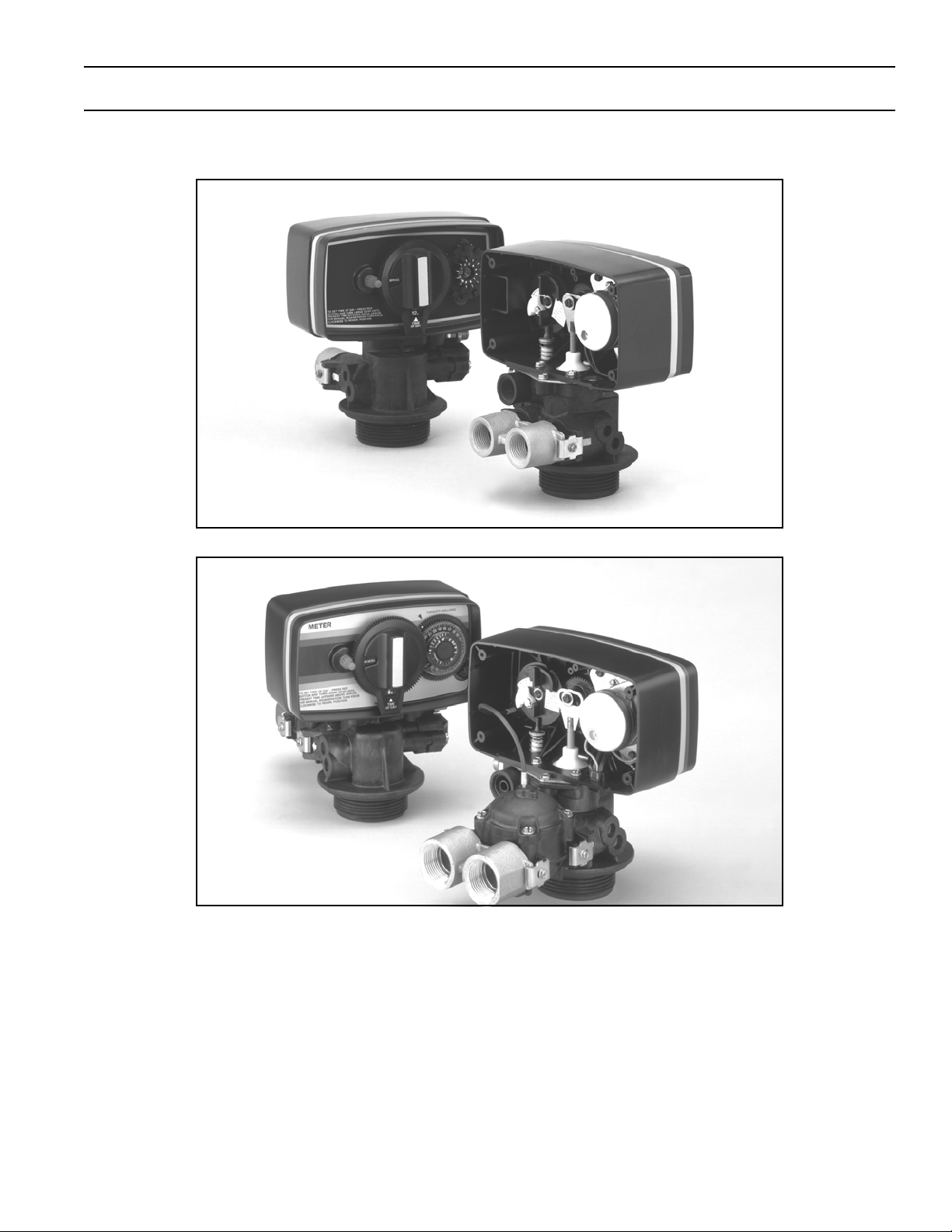
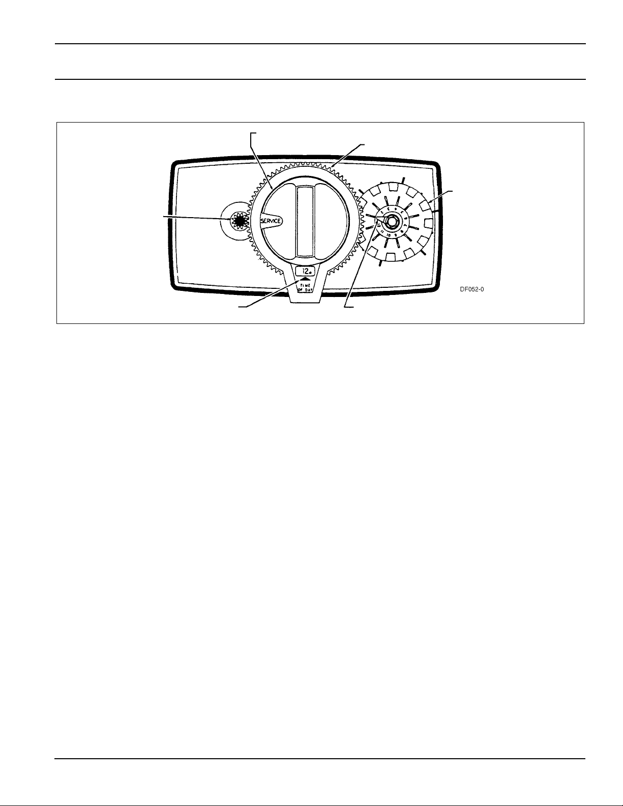
Model 5600 Installation and Start-up Procedures
NOTE: Install the water softener with the inlet, outlet and drain connections made according to manufacturer’s
recommendations and to meet applicable plumbing codes.
Manual
Red Time
Button
Set
Regeneration Knob
24-Hour Gear
Skipper Wheel
(shows every
other day
regeneration)
Time of Day Arrow
Figure 1: Model 5600 Softener Control
1. Manually index the softener control into the In Service position and let water flow into the resin tank. When the water
flow stops, open a softened water tap until all air is released from the lines. Then close tap.
NOTE: Manually dial the various regeneration positions by turning the knob on the front of the control until the indicator
shows that the softener is in the desired position.
2. Manually index the control to the Backwash position and allow water to flow at the drain for 3 or 4 minutes.
3. Remove back cover plate.
4. Make sure that the salt dosage is set as recommended by the manufacturer. If necessary, set salt according to the setting
instruction sheet. Manually index the control to the Brine Fill position and allow the brine tank to fill to the top of the air
check.
5. Manually index the control to the Brine Draw position and allow the control to draw water from the brine tank until it
stops.
6. Plug in the electrical cord and look in the sight hole in the back of the motor to see that it is running. Set the days that
regeneration is to occur by sliding tabs on skipper wheel outward to expose trip fingers.
— Each tab is one day.
— Finger at red pointer is tonight.
— Moving clockwise from red pointer, extend or retract fingers to obtain the desired regeneration schedule.
7. Manually advance the control to the beginning of the Brine Fill position and allow the control to return to the In Service
position automatically.
8. Fill the brine tank with salt.
9. Replace back cover on the control.
Red Pointer
10. Make sure that any bypass valving is left in the normal In Service position.
6
Model 5600 & 5600 Econominder
®
Model 5600 Backwash Filter Installation and Start-up Procedures
NOTE: Install the water softener with the inlet, outlet and drain connections made according to manufacturer’s
recommendations and to meet applicable plumbing codes.
Manual
Red Time
Set
Button
Regeneration Knob
24-Hour Gear
Skipper Wheel
(shows every
other day
backwash)
Time of Day Arrow
Figure 2: Model 5600 Backwash Filter Control
Red Pointer
Before Plugging in the Unit
1. Open a treated water tap down stream of the filter.
2. Manually index the filter to the In Service position and allow the mineral tank to fill by slowly opening the main water
supply valve. Any bypass should be in the In Service position.
NOTE: The water flowing from the downstream tap is cloudy and/or contains media fines as well as air. Allow the water
to run until it appears clean and free of air.
3. When a steady clean flow appears at the tap, close the tap and the main water supply valve and allow the filter media bed
to settle for 15–20 minutes.
4. Manually index the filter to the Backwash position.
5. To prevent a sudden surge of water and air, partially open the main water supply valve so that the flow at the drain of the
filter is approximately 1 gpm. The water at the drain is cloudy again and/or contains media fines as well as air. Allow
water to flow at the drain until it appears clean and free of air.
6. Continue to open the water supply valve until it is completely open. Allow water to flow at the drain until all media fines
are washed out of the filter.
7. Manually index the filter to the In Service position, and again open the downstream tap. Check to be sure that the water
flows clear. If necessary, allow water to flow until all media fines are gone. If the tap is equipped with an aerator check
that is not plugged with media fines and pipe scale.
8. Plug in the electrical cord and look in the sight hole on the back of the timer motor to ensure that it is running. Set the days
backwashing is to occur by sliding tabs on the skipper wheel outward to expose trip fingers. Each tab is one day. Finger at
red pointer is tonight. Moving clockwise from red pointer, extend or retract fingers to obtain the desired backwash
schedule.
9. Set time of day by pushing red button and spin the 24-hour gear until the present time of day is visible above the time of
day arrow.
7

Model 5600 & 5600 Econominder
®
Model 5600 Backwash Filter Installation and Start-up Procedures
(Cont’d.)
Cycle Times and Flow Diagrams
1. In Service position. See Figure 4, page 10.
2. Preliminary Rinse position.
— Same as Figure 4, page 10 with standard piston (white end plug) or filter piston (black end plug).
— Eliminated with low water piston (gray end plug).
3. Backwash position.
— Same as Figure 6, page 11 with standard piston.
— 15 minutes with filter piston.
— 7 minutes with low water piston.
4. Brine Rinse position.
— Eliminated, resulting in a 50 minute pause, no water flows during this time.
5. Slow Rinse position.
— Eliminated, resulting in a 50 minute pause, no water flows during this time.
6. Second Backwash position.
— Same as Figure 9, page 12 with standard piston.
— 15 minutes with filter piston.
— 7 minutes with low water piston.
7. Settling Rinse position.
— Same as Figure 10, page 13 with standard or filter piston.
— Eliminate with low water piston.
8. Brine Tank Refill position.
— Eliminated, filter is back in service at this time.
8
Model 5600 & 5600 Econominder
®
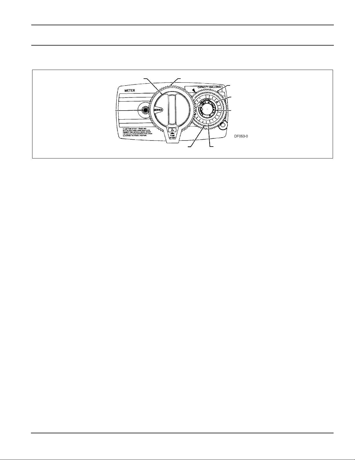
Model 5600 Econominder Installation and Start-up Procedures
NOTE: Install the water softener with the inlet, outlet and drain connections made according to manufacturer’s
recommendations and to meet applicable plumbing codes.
Manual
1. Manually index the softener control to the In Service position and let water flow into the resin tank. When the water flow
stops, open a softened water tap until all air is released from the lines. Then close tap.
NOTE: The various regeneration positions may be dialed manually by turning the knob on the front of the control until
the indicator shows that the softener is in the desired position.
2. Set water usage program wheel using any one of the following procedures:
— Typical Residential Application
To program, just set the time, set the hardness and it automatically monitors system needs and regenerates only when
necessary. To set time of day press red time set button and turn 24-hour gear until present time of day is at “time of
day.” Set program wheel by lifting the “people” dial and rotating it so that the number of people in the household is
aligned with the household grains per gallon water hardness. Release the dial and check for firm engagement at
setting. This method provides reserve capacity based on 75 gallons per person.
— Optional Programming Procedures
Calculate the gallon capacity of the system, subtract the necessary reserve requirement and set the gallons available at
the small white dot on program wheel gear. Note, drawing shows 850 gallon setting. The capacity (gallons) arrow
denotes remaining gallons exclusive of fixed reserve.
Regeneration Knob
Red Time
Set
Button
24-Hour Gear
White Dot
Figure 3: Model 5600 Econominder
Program Wheel
People Dial
Grains Per Gallon
Water Hardness
Scale
Gallons Label
3. Rotate program wheel counterclockwise until it stops at Regeneration position.
4. Manually index the control to the Backwash position and allow water to flow at the drain for 3 or 4 minutes.
5. Remove back cover plate.
6. Make sure than the salt dosage is set as recommended by the manufacturer. Manually index the control to the Brine Fill
position and allow the brine tank to fill to the top of the air check.
7. Manually index the control to the Brine Rinse position and allow the control to draw water from the brine tank until it
stops.
8. Plug in the electrical cord and look in the sight hole in the back of the monitor to see that it is running.
9. Manually advance the control to the beginning of the Brine Fill position and allow the control to return to the In Service
position automatically.
10. Fill the brine tank with salt.
11. Replace back cover on the control. Be sure cable is not pinched between cover and housing.
12. Make sure that any bypass valving is left in the normal In Service position.
9
Model 5600 & 5600 Econominder
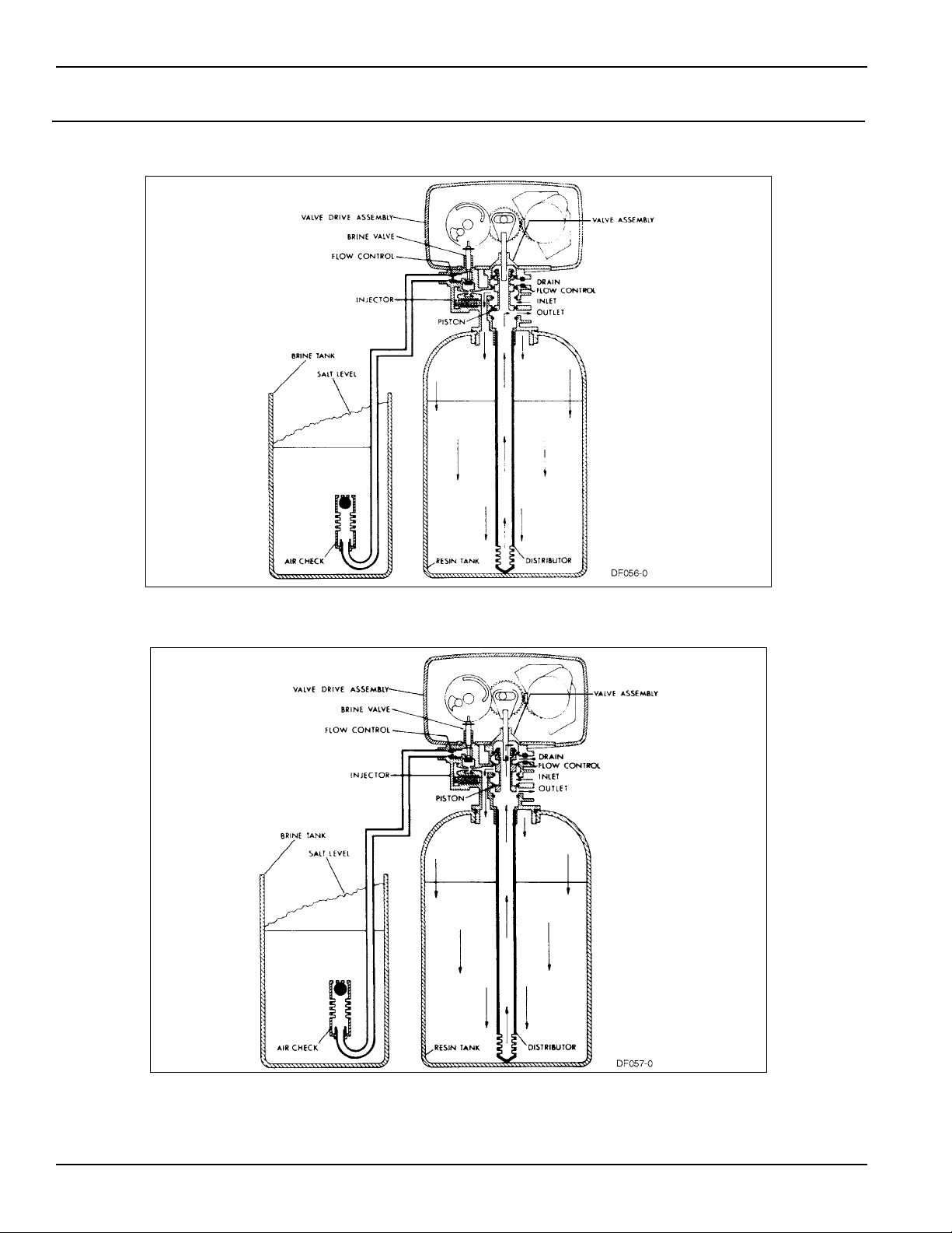
Water Conditioner Flow Diagrams
Service Position
®
Preliminary Rinse Position
Figure 4: Service Position
10
Figure 5: Preliminary Rinse Position
Model 5600 & 5600 Econominder
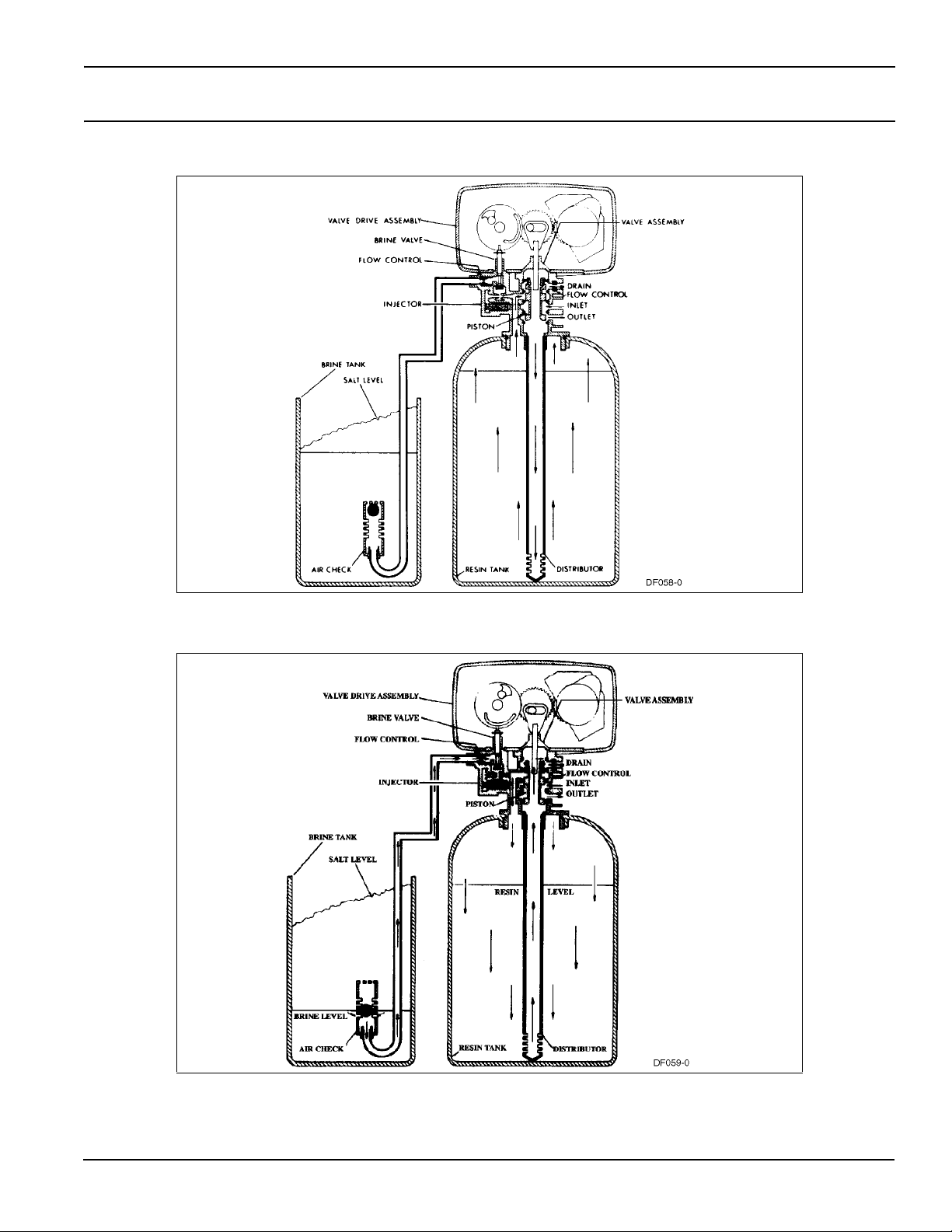
Water Conditioner Flow Diagrams (Cont’d.)
Backwash Position
®
Brine Position
Figure 6: Backwash Position
Figure 7: Brine Position
11
Loading…
Скачать файл PDF «Pentair Water Pool and Spa Water Dispenser Model 5600 & 5600 Econominder Инструкция по эксплуатации» (1.26 Mb)
Популярность:
8237 просмотры
Подсчет страниц:
36 страницы
Тип файла:
Размер файла:
1.26 Mb
Google Ads:
- Главная
-
Pentair
-
Фильтры для плавательного бассейна
-
AquaTech
На этой странице вы найдёте полный список документов на Фильтры для плавательного бассейна Pentair AquaTech.
Выберите необходимый PDF файл.
-
Фильтры для плавательного бассейна
Pentair AquaTech Инструкция по эксплуатацииТип файла
PDFРазмер
99 KbКол-во страниц
4Просмотров
1602Download / Read online
- 1
Другие Pentair Фильтры для плавательного бассейна
-
Pentair D.E. Cartridge Style Filter Инструкция по эксплуатации
PDF файлов
1Просмотров
3450 -
Pentair D.E. Cartridge Style Filter Quad D.E. Инструкция по эксплуатации
PDF файлов
1Просмотров
3227 -
Pentair FNS Plus Инструкция по эксплуатации
PDF файлов
1Просмотров
2602 -
Pentair System 3 S8M600 Инструкция по эксплуатации
PDF файлов
1Просмотров
2534 -
Pentair AquaTech Инструкция по эксплуатации
PDF файлов
1Просмотров
2210 -
Pentair Filter CFW Series Инструкция по эксплуатации
PDF файлов
1Просмотров
1969
Другие устройства Pentair
-
Автомобильные видеосистемы
Pentair Intellitouch ScreenLogic Инструкция по эксплуатацииPDF файлов
1Просмотров
15441 -
Сетевые карты
Pentair Pool and Spa Control System SunTouch Инструкция по эксплуатацииPDF файлов
1Просмотров
13530 -
Гидромассажные ванны
Pentair Pool & Spa Heaters NT Series Инструкция по эксплуатацииPDF файлов
1Просмотров
11478 -
Нагреватель воды для бассейна
Pentair MiniMax 200 Инструкция по эксплуатацииPDF файлов
1Просмотров
11103 -
Вакуумные пылесосы для плавательного бассейна
Pentair GreatWhite Automatic Pool Cleaner Инструкция по эксплуатацииPDF файлов
1Просмотров
10932 -
Диспенсеры для воды (Кулеры для воды)
Pentair Water Pool and Spa Water Dispenser Model 5600 & 5600 Econominder Инструкция по эксплуатацииPDF файлов
1Просмотров
9474
Ранее вы смотрели
Производители
ADC
Alliance Laundry Systems
Blodgett
Farenheit Technologies
Intec
Olivetti
Simplicity
Topcom
TrueAir
TV Guide On Screen
Типы устройств
Видеокамеры
Интерфейсы ввода-вывода
Жерновые кофемолки
Лифтовое оборудование
Бурение
Теплицы и расходные материалы для них
Тиски и струбцины
Лампочки индикаторы
Замки
Продукт домашнего изготовления
Устройства
Cisco Systems E-1 6911
Keating Of Chicago Miraclean 2724
Kenmore elite 2709
KitchenAid KPEC992MSS1
Linear DMC1PACK/ Music/ Communication System Package
Makita JRl80DWB
Miller Electric Big Blue 251D
Pioneer DV-PT100
Socket Mobile Series 7
Speco Technologies SP-6AWD/T-W
freeuserguide.ru
About Us
Contacts
Disclamers
Privacy Policy
Эта страница полезна для вас? Поделитесь ссылкой:
- Topics
- manualsbase, manuals,
- Collection
- manuals_contributions; manuals; additional_collections
- Language
- English
- Item Size
- 13.6M
- Addeddate
- 2020-08-17 09:03:34
- Identifier
- manualsbase-id-545220
- Identifier-ark
- ark:/13960/t6066pv08
- Ocr
- ABBYY FineReader 11.0 (Extended OCR)
- Page_number_confidence
- 94.29
- Ppi
- 300
- Scanner
- Internet Archive Python library 1.9.4
plus-circle Add Review
plus-circle Add Review
comment
Reviews
There are no reviews yet. Be the first one to
write a review.
87
Views
DOWNLOAD OPTIONS
download 1 file
ABBYY GZ download
Temporarily Unavailable
DAISY
For users with print-disabilities
Temporarily Unavailable
EPUB
download 1 file
FULL TEXT download
download 1 file
ITEM TILE download
download 1 file
PAGE NUMBERS JSON download
download 1 file
PDF download
download 1 file
SINGLE PAGE PROCESSED JP2 ZIP download
download 1 file
TORRENT download
download 12 Files
download 6 Original
SHOW ALL
IN COLLECTIONS
Manuals: Contributions Inbox
The Manual Library
Additional Collections
Uploaded by
chris85
on