
CPU
1
3
2
4
5
6
7
9
10
8
1 2
109
HDD LED + Power LED +
HDD LED — Power LED —
Reset Switch Power Switch
Reset Switch Power Switch
Reserved No Pin
RESET SW
POWER SW
POWER LED+
POWER LED-
HDD LED
HDD LED
RESET SW
JFP1
HDD LED
HDD LED +
HDD LED —
POWER LED
Power LED +
Power LED —
Front panel
Vorderseite
Panneau avant
Передняя панель
Przedni panel
Painel frontal
Painel frontal
Panel frontal
Ön panel
Frontpanel
Voorkant
Frontpanel
Čelní panel
Πρόσοψη
Frontpanel
Etupaneeli
Előlapi panel
Pannello anteriore
Алдыңғы панель
前面板
前面板
フロントパネル
전면 패널
Pa-nen trước
แผงหน้า
Panel depan
Передня панель
Panou frontal
Predný panel
Prednja tabla
Челен панел
Priekšējais panelis
Prednji panel
Sprednja plošča
Priekinis skydas
Prednja ploča
Esipaneel
Intel 20XX CPU
Memory
Speicher
Mémoire
Память
Pamięć
Memória
Memória
Memoria
Bellek
Hukommelse
Geheugen
Minne
Paměť
Μνήμη
Minne
Muisti
Memória
Memoria
Жад
記憶體
内存
メモリ
메모리
Bộ nhớ
หน่วยความจำ
Memori
Пам’ять
Memorie
Pamäť
Memorija
Памет
Atmiņa
Memorija
Pomnilnik
Atmintis
Memorija
Mälu
Intel 115X CPU AMD TR4 CPU
AMD CPU
ةﺮﻛاﺬﻟا
ﻪﻈﻓﺎﺣ
ম
েরিম
ﺔﻴﻣﺎﻣﻷا ﺔﺣﻮﻠﻟا
ﻮﻠﺟ ﻞﻨﭘ
সুখ া নে ল
Quick Installation Guide
English ● Deutsch ● Français ● Русский ● Polski ● Português ●
BR Portuguese ● Español ● Türkçe ● Dansk ● Nederlands ● Norsk ●
Česky ● Ελληνικά ● Svenska ● Suomi ● Magyar ● Italiano ● Қазақ тілі ●
繁體中文 ● 簡体中文 ● 日本語 ● 한국어 ● Tieng Viet ● ไทย ●
Bahasa Indonesia ● Українська ● Română ● Slovensky ● Bosanski ●
Български ● Latviski ● Srpski ● Slovenščina ● Lietuvių ● Hrvatski ●
Eesti ● ﺔﻴﺑﺮﻌﻟا ● ﯽﺳرﺎﻓ ● বাঙািল ●
This quick guide is only for common personal computer assembly. For detailed
installation and information please refer to the users’ manual. The content is subject to
change without notice. All brand names are registered trademarks of their respective
owners. Please visit www.msi.com for more information.
If you purchase the motherboard with a HDMI connector, you can
connect it to HDMI compatibility Audio-Visual equipments.
TM
G52-XXXX27K
MOTHERBOARD
MSI Warranty Procedures and Conditions (This is only valid for Australia)
The terms and conditions of MSI’s warranty described herein adhere to the guidelines
set forth by the Australian Competition & Consumer Commission (“ACCC”), in addition to
the applicable provisions under the Australian Consumer Law (”ACL”). Our goods come
with guarantees that cannot be excluded under the Australian Consumer Law. You are
entitled to a replacement or refund for a major failure and for compensation for any
other reasonably foreseeable loss or damage. You are also entitled to have the goods
repaired or replaced if the goods fail to be of acceptable quality and the failure does not
amount to a major failure.
(1) Determination of the warranty period: The warranty period starts from the date you
purchase the Product with valid invoice. If the last day of the warranty period is a national
holiday, the following day shall be the last day of the warranty period.
(2) Customer-Induced-Defect (CID): If the problems or symptoms are complied with
improper usage defined as Customer-Induced-Defect (CID), shall not be accepted in
warranty claim of the product set. MSI reserves the right to determine whether the
products are operated within the scope of proper usage.
(3) Limited warranty for software: The software not pre-installed is not covered within
the Product’s warranty .The Company assumes no responsibility for any software
subsequently installed by the customer itself and any possible consequential breakdown
or damage.
(4) Screen the problems by self-checking:
• Please first review the User’s Manual and contents of the Software CD included with
the Product:The User’s Manual and Software CD provided by MSI containing a lot of
information about product use. The manual we compose from user’s perspective can
answer many of your questions. If your manual has been lost; you may download the
manual you need from the MSI website.
• Visit MSI website for support: MSI retains a group of customer service engineers with
profession and knowledge. You may post a message about the problem you encounter on
MSI’s categorized discussion forum, and our engineers will try their best to answer your
question concerning product use immediately. Or you may search on the website for FAQ,
to see whether there is any solution for similar problems.
(5) Seek support from the original store of purchase: If you cannot seek any solution for
the problem out of the above methods, you may seek support from the original store of
purchase, because the original store of purchase should best know your system
configuration and specifications, and can provide you with any necessary resource and
service.
(6) Bring the Product to the original store of purchase: If your product has been
determined by the MSI engineer or store as problematic or defective in hardware, and
may incur the need for replacement of parts, you may bring the Product for repair or
replacement to the original store of purchase to send the Product for repair or
replacement on your behalf. However, the customer must properly pack the Product
when sending it for repair, to avoid further damage in the course of shipping.
(7) Warranty receipt: The valid invoice of your purchase shall be provided for the
warranty service.
(8) Contacts: In the event that additional assistance is required, please contact MSI
Australia Pty at the following:
Unit 16, 22 Princes Rd East Auburn NSW 2144, Australia
Tel: 02 9748 0070
Email: ausrma@msi.com
For more details, please visit our website www.au.msi.com
11
1
1
1
2
2
2
2
3
3
2
3
3
4
4
3
5
5
4
6
6
5
8
8
9
9
10
10
11
12
13
16
14
17
18
15
7
7
7
6
8
Motherboard
Motherboard
Carte mère
Материнская плата
Płyta główna
Motherboard
Placa-mãe
Placa base
Ana Kart
Systemkort
Moederbord
Hovedkort
Základní deska
Μητρική πλακέτα
Moderkort
Emolevy
Alaplap
Scheda madre
Негізгі тақта
主機板
主板
マザーボード
마더보드
Bo mạch chủ
บอร์ดหลัก
Motherboard
Материнська плата
Placă de bază
Základná doska
Matična ploča
Главна платка
Mātesplate
Matična ploča
Matična plošča
Pagrindinė plokštė
Matična ploča
Emaplaat
Graphics card
Grafikkarte
Carte graphique
Видеокарта
Karta graficzna
Placa gráfica
Placa de vídeo
Tarjeta gráfica
Grafik kartı
Grafikkort
Videokaart
Grafikkort
Grafická karta
Κάρτα γραφικών
Grafikkort
Näytönohjain
Grafikus kártya
Scheda grafica
Графикалық карта
顯示卡
显卡
グラフィックカード
그래픽 카드
Thẻ đồ họa
การ์ดกราฟิก
Kartu grafis
Графічна карта
Card video
Grafická karta
Grafička kartica
Видео карта
Grafikas karte
Grafička kartica
Grafična kartica
Grafinė plokštė
Grafička kartica
Graafikakaart
Power on
Einschalten
Allumé
Включение питания
Wł. zasilanie
Ligado
Ligar
Encendido
Güç aç
Tænde
Inschakelen
Strøm på
Zapnutí
Ενεργοποίηση
Ström på
Virta päälle
Bekapcsolás
Accensione
Қуат қосулы
開機
开机
電源オン
전원 켜기
Bật nguồn
เปิด
Daya nyala
Увімкнення живлення
Pornire alimentare
Zapnutie
Napajanje uključeno
Включване
Ieslēgt
Uključivanje
Vklop
Maitinimas įjungtas
Uključivanje
Toide sisse
পাওয়ার অন
Peripheral devices
Periphere Geräte
Périphériques
Периферийные устройства
Urządzenia zewnętrzne
Dispositivos periféricos
Dispositivos periféricos
Dispositivos periféricos
Çevresel aygıtlar
Perifere enheder
Randapparatuur
Periferenheter
Periferní zařízení
Περιφερειακές συσκευές
Kringutrustning
Oheislaitteet
Perifériák
Dispositivi periferici
Перифериялық құрылғылар
周邊設備
外围设备
周辺機器
주변 장치
Thiết bị ngoại vi
อุปกรณ์รอบข้าง
Perangkat periferal
Периферійні пристрої
Dispozitive periferice
Periférne zariadenia
Periferni uređaji
Периферни устройства
Perifērijas ierīces
Periferni uređaji
Zunanje naprave
Išoriniai įtaisai
Vanski uređaji
Välisseadmed
েপিরেফরাল িডভাইসসমূহ
Software
Software
Logiciel
Программное обеспечение
Oprogramowanie
Software
Software
Software
Yazılım
Software
Software
Programvare
Software
Λογισμικό
Program
Ohjelmisto
Szoftver
Software
Бағдарламалық жасақтама
軟體
软件
ソフトウェア
소프트웨어
Phần mềm
ซอฟต์แวร์
Perangkat lunak
Програмне забезпечення
Software
Softvér
Softver
Софтуер
Programmatūra
Softver
Programska oprema
Programinė įranga
Softver
Tarkvara
M.2 Module
M.2 Modul
Module M.2
Модуль M.2
Moduł M.2
Módulo M.2
Módulo M.2
Módulo M.2
M.2 Modülü
M.2-modul
M.2-module
M.2-modul
Modul M.2
Μονάδα Μ.2
M.2-modul
M.2-moduuli
M.2 modul
Modulo M.2
M.2 модулі
M.2模組
M.2模块
M.2モジュール
M.2 모듈
Mô-đun M.2
โมดูล M.2
Modul M.2
Модуль M.2
Modul M.2
Modul M.2
M.2 modul
Модул М.2
M.2 Modulis
M.2 modul
Modul M.2
M.2 modulis
M.2 modul
M.2 moodul
M.2
M.2
M.2 মিডউল
M.2
ةﺪﺣو
لوژﺎﻣ
مﻷا ﺔﺣﻮﻠﻟا
درﻮﺑردﺎﻣ
تﺎﻣﻮﺳﺮﻟا ﺔﻗﺎﻄﺑ
ﮏﯿﻓاﺮﮔ ترﺎﮐ
ািফ কাড
Power connectors
Stromanschlüsse
Connecteur d’alimentation
Сетевые разъемы
Złącza zasilania
Conectores de energia
Conectores de alimentação
Conectores de alimentación
Güç bağlayıcıları
Strømstik
Stroomaansluitingen
Strømkontakter
Napájecí konektory
Υποδοχές ισχύος
Kontaktdon
Virtaliittimet
Tápcsatlakozók
Connettori di alimentazione
Қуат жалғағыштары
電源接頭
电源接口
電源コネクタ
전원 커넥터
Các đầu nối điện
สายคอนเน็คเตอร์
Konektor daya
Роз’єми живлення
Conectori alimentare
Napájacie konektory
Konektori napajanja
Изводи за захранване
Strāvas savienotāji
Konektori za napajanje
Priključki za napajanje
Galios jungtys
Priključci napajanja
Toite ühendused
ﺔﻗﺎﻄﻟا تﻼﺻﻮﻣ
روﺎﭘ یﺎﻫرﻮﺘﮑﻧﺎﮐ
SATA drive
SATA Laufwerk
Lecteur SATA
Дисковод SATA
Dysk SATA
Drive SATA
Unidade SATA
Unidad SATA
SATA sürücü
SATA-drev
SATA-station
SATA-stasjon
Disk SATA
Μονάδα δίσκου SATA
SATA-enhet
SATA-asema
SATA meghajtó
Unità SATA
SATA дискі
SATA裝置
SATA驱动器
SATAドライブ
SATA 장치
Ổ SATA
ไดร้ฟว์ SATA
Drive SATA
Диск SATA
Unitate SATA
Jednotka SATA
SATA pogonska jedinica
SATA устройство
SATA dzinis
SATA disk
Pogon SATA
SATA diskas
SATA pogon
SATA draiv
SATA
SATA
SATA
SATA
كﺮﺤﻣ
ﻮﯾارد
াইভ
ﺔﻴﻓﺮﻄﻟا ةﺰﻬﺟﻷا
ﯽﺒﻧﺎﺟ یﺎﻫ هﺎﮕﺘﺳد
ﺔﻗﺎﻄﻟا ﻞﻴﻐﺸﺗ
روﺎﭘ غاﺮﭼ ﺞﻣﺎﻧﺮﺒﻟا
راﺰﻓا مﺮﻧ
5
7
6
1
2
4
1
2
3
4
3
1
2
3
4
5
30°
1
11
2
2
2
3
4
1
2
345
1
Quick Start
Quick Start
Thank you for purchasing the MSI
®
MPG X570 GAMING EDGE WIFI motherboard.
This Quick Start section provides demonstration diagrams about how to install your
computer. Some of the installations also provide video demonstrations. Please link to
the URL to watch it with the web browser on your phone or tablet. You may have even
link to the URL by scanning the QR code.
Preparing Tools and Components
DDR4 Memory
Graphics Card
SATA Hard Disk Drive
SATA DVD Drive
Phillips Screwdriver
Chassis
Power Supply Unit
A Package of Screws
Thermal Paste
CPU Fan
AMD
®
AM4 CPU

SPECIFICATION
MOTHERBOARD
MOTHERBOARD
MPG X570 GAMING EDGE WIFI GAME IN
MPG X570 GAMING EDGE WIFI GAME IN
STYLE
STYLE
FEATURE
Frozr Heatsink Design
Designed with the patented fan and double ball bearings to
provide best performance for enthusiast gamers and
prosumers.
Core Boost
With premium layout and fully digital power design to support
more cores and provide better performance.
Extended Heatsink Design
MSI extended PWM and enhanced circuit design ensures
even high-end processors to run in full speed.
Pre-installed I/O Shielding
Better EMI protection and more convenience for installation
Model Name MPG X570 GAMING EDGE WIFI
CPU Support Supports 2nd and 3rd Gen AMD Ryzen™ / Ryzen™ with
CPU Socket Socket AM4
Chipset
Graphics Interface 2 x PCI-E 4.0 x16 slots
Display Interface HDMI – Requires Processor Graphics
Memory Support 4 DIMMs, Dual Channel DDR4
Expansion Slots 3x PCIe 3.0 x1 slots
Storage 1 x Lightning M.2 slot (Gen4 x4) + 1 x Turbo M.2 slot (Gen3
USB Ports 4 x USB 3.2(Gen2, 3A+1C) + 6 x USB 3.2(Gen1) + 6 x USB
LAN
Wireless / BT
Audio 8-Channel(7.1) HD Audio with Audio Boost 4
Radeon™ Vega Graphics and 2nd Gen AMD Ryzen™ with
Radeon™ Graphics Desktop Processors
AMD® X570 Chipset
Supports 2-Way AMD® CrossFire™ Technology
x4)
6 x SATA 6Gb/s
2.0
Realtek® RTL8111H Gigabit LAN
Intel® Wireless-AC 3168, Bluetooth 4.2
CONNECTIONS
Lightning Gen4 solution
The latest Gen4 PCI-E and M.2 solution with up to 64GB/s
bandwidth for maximum transfer speed.
M.2 Shield FROZR
Strengthened built-in M.2 thermal solution. Keeps M.2 SSDs
safe while preventing throttling, making them run faster.
Audio Boost 4
Isolated audio with a high quality audio processor for the
most immersive gaming experience.
Flash BIOS Button
Simply use a USB key to flash any BIOS within seconds,
without installing a CPU, memory or graphics card.
Keyboard / Mouse1.
Wireless / Bluetooth2.
USB 3.2 Gen1 Type-A3.
LAN4.
Audio Connectors5.
Flash BIOS Button6.
© 2018 Micro-Star Int’l Co.Ltd. MSI is a registered trademark of Micro-Star Int’l Co.Ltd. All rights reserved.
© 2018 Micro-Star Int’l Co.Ltd. MSI is a registered trademark of Micro-Star Int’l Co.Ltd. All rights reserved.
USB 2.07.
HDMI8.
USB 3.2 Gen2 Type-A + C9.
USB 3.2 Gen2 Type-A10.
Optical S/PDIF out11.
Generated 2019-06-25, check for the latest version www.msi.com/datasheet. The information provided in this document is intended for informational purposes only and is subject to change without notice.
Loading…
Description
This PDF user manual is for the MSI MPG X570 GAMING EDGE WIFI Motherboard.
About the Item
MSI MPG X570 GAMING EDGE WIFI Motherboard
Version 1.0, 2019/05, First release.
Version 1.1, 2019/08, Updated storage SPEC.
(PDF) USER MANUAL (ENGLISH)
SUMMARY OF CONTENTS
QUICK START
This Quick Start section provides demonstration diagrams about how to install your computer. Some of the installations also provide video demonstrations.
– Preparing Tools and Components
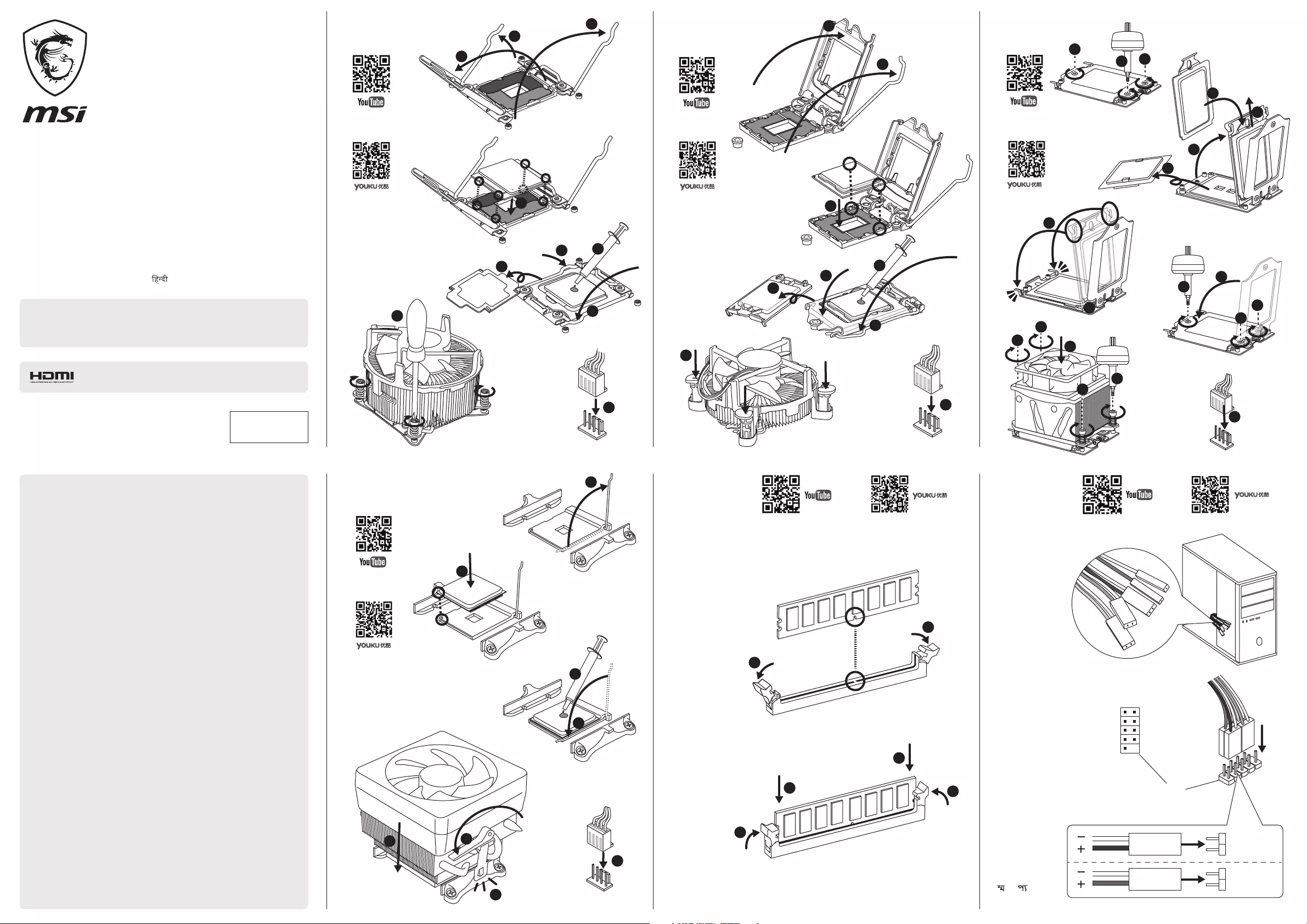
– Installing a Processor
– Installing DDR4 memory
– Connecting the Front Panel Header
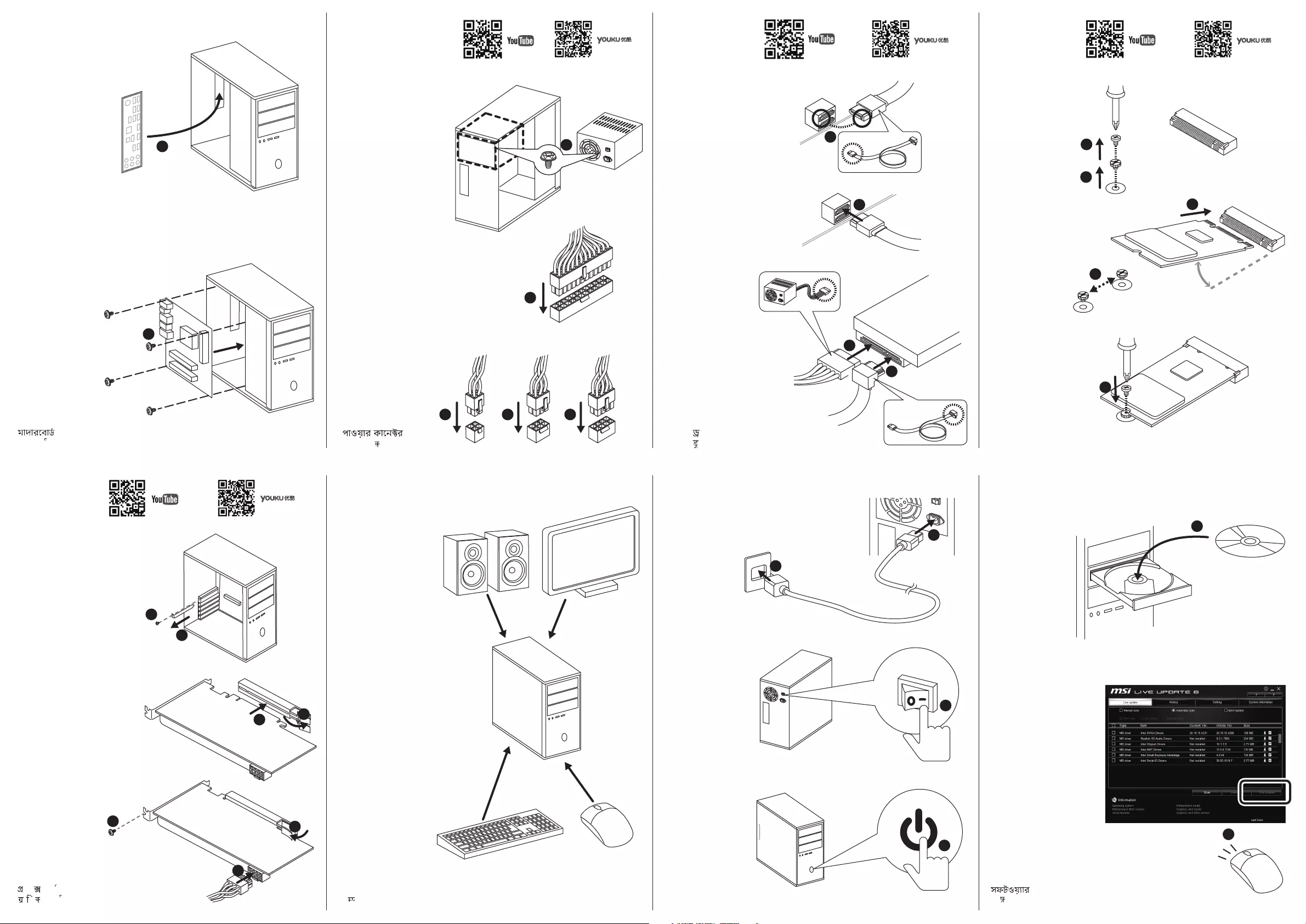
– Installing the Motherboard
– Connecting the Power Connectors
– Installing SATA Drives
– Installing a Graphics Card
– Connecting Peripheral Devices
– Power On
SPECIFICATIONS
PACKAGE CONTENTS
BLOCK DIAGRAM
REAR I/O PANEL
– LAN Port LED Status Table
– Audio Ports Configuration
– Realtek Audio Console
OVERVIEW OF COMPONENTS
– CPU Socket
– DIMM Slots
– PCI_E1~5: PCIe Expansion Slots
– M2_1~2: M.2 Slots (Key M)
– SATA1~6: SATA 6Gb/s Connectors
– JFP1, JFP2: Front Panel Connectors
– CPU_PWR1~2, ATX_PWR1: Power Connectors
– CPU_FAN1, PUMP_FAN1, SYS_FAN1~4: Fan Connectors
– JUSB3~4: USB 3.2 Gen1 Connectors
– JUSB1~2: USB 2.0 Connectors
– JAUD1: Front Audio Connector
– JCOM1: Serial Port Connector
– JCI1: Chassis Intrusion Connector
– JBAT1: Clear CMOS (Reset BIOS) Jumper
– EZ Debug LED
– JRGB1~2: RGB LED connectors
– JRAINBOW1~2: Addressable RGB LED connectors
INSTALLING OS, DRIVERS & UTILITIES
– Installing Windows 10
– Installing Drivers
– Installing Utilities
BIOS SETUP
– Entering BIOS Setup
– Resetting BIOS
– Updating BIOS
– EZ Mode
– Advanced Mode
– SETTINGS
– Advanced
– Boot
– Security
– Save & Exit
– OC
– M-FLASH
– OC PROFILE
– HARDWARE MONITOR
– A-XMP Operation
NAHIMIC 3
– Installation and Update
– Audio Tab
– Microphone Tab
– Sound Tracker Tab
– Settings Tab
AMD RAID CONFIGURATION
– Enabling RAIDXpert2 Configuration Utility
– Initializing Disks
– Creating Arrays
– Deleting Arrays
– Installing RAID Driver
TROUBLESHOOTING
Why download the Manual?
This user manual provides all the information from MSI / Micro-Star about the MPG X570 GAMING EDGE WIFI Motherboard, as detailed in the table of contents. Reading it completely will address most questions you might have. You can download and save it for offline use, including viewing it on your device or printing it for your convenience if you prefer a paper version.
How to download the Manual?
Download it by clicking the button below
Helped you out?
Glad to hear that. It would be awesome if you could . . .

1
Quick Start
Quick Start
Thank you for purchasing the MSI
®
MPG X570 GAMING EDGE WIFI motherboard.
This Quick Start section provides demonstration diagrams about how to install your
computer. Some of the installations also provide video demonstrations. Please link to
the URL to watch it with the web browser on your phone or tablet. You may have even
link to the URL by scanning the QR code.
Preparing Tools and Components
DDR4 Memory
Graphics Card
SATA Hard Disk Drive
SATA DVD Drive
Phillips Screwdriver
Chassis
Power Supply Unit
A Package of Screws
Thermal Paste
CPU Fan
AMD
®
AM4 CPU

2
Quick Start
Safety Information
y The components included in this package are prone to damage from electrostatic
discharge (ESD). Please adhere to the following instructions to ensure successful
computer assembly.
y Ensure that all components are securely connected. Loose connections may cause
the computer to not recognize a component or fail to start.
y Hold the motherboard by the edges to avoid touching sensitive components.
y It is recommended to wear an electrostatic discharge (ESD) wrist strap when
handling the motherboard to prevent electrostatic damage. If an ESD wrist strap is
not available, discharge yourself of static electricity by touching another metal object
before handling the motherboard.
y Store the motherboard in an electrostatic shielding container or on an anti-static pad
whenever the motherboard is not installed.
y Before turning on the computer, ensure that there are no loose screws or metal
components on the motherboard or anywhere within the computer case.
y Do not boot the computer before installation is completed. This could cause
permanent damage to the components as well as injury to the user.
y If you need help during any installation step, please consult a certified computer
technician.
y Always turn off the power supply and unplug the power cord from the power outlet
before installing or removing any computer component.
y Keep this user guide for future reference.
y Keep this motherboard away from humidity.
y Make sure that your electrical outlet provides the same voltage as is indicated on the
PSU, before connecting the PSU to the electrical outlet.
y Place the power cord such a way that people can not step on it. Do not place anything
over the power cord.
y All cautions and warnings on the motherboard should be noted.
y If any of the following situations arises, get the motherboard checked by service
personnel:
Liquid has penetrated into the computer.
The motherboard has been exposed to moisture.
The motherboard does not work well or you can not get it work according to user
guide.
The motherboard has been dropped and damaged.
The motherboard has obvious sign of breakage.
y Do not leave this motherboard in an environment above 60°C (140°F), it may damage
the motherboard.

4
Quick Start
1
2
3
Important
If you are installing the screw-type CPU heatsink, please follow the figure below to
remove the retention module first and then install the heatsink.

6
Quick Start
HDD LED
RESET SW
Connecting the Front Panel Header
JFP1
HDD LED
HDD LED —
HDD LED +
POWER LED —
POWER LED +
POWER LED
1
2 10
9
+
+
+—
——
—
+
Power LED
HDD LED Reset Switch
Reserved
Power Switch
JFP1
1 HDD LED + 2 Power LED +
3 HDD LED — 4 Power LED —
5 Reset Switch 6 Power Switch
7 Reset Switch 8 Power Switch
9 Reserved 10 No Pin
RESET SW
POWER SW
POWER LED+
POWER LED-
HDD LED

8
Quick Start
Connecting the Power Connectors
ATX_PWR1
CPU_PWR1
CPU_PWR2

10
Quick Start
1
Installing a Graphics Card
2
3
4
5
6

11
Quick Start
Connecting Peripheral Devices
Processor with integrated graphics

13
Contents
Contents
Quick Start ………………………………………………………………………………………………. 1
Preparing Tools and Components ……………………………………………………………….. 1
Safety Information …………………………………………………………………………………….. 2
Installing a Processor ………………………………………………………………………………… 3
Installing DDR4 memory ……………………………………………………………………………. 5
Connecting the Front Panel Header …………………………………………………………….. 6
Installing the Motherboard …………………………………………………………………………. 7
Connecting the Power Connectors ………………………………………………………………. 8
Installing SATA Drives………………………………………………………………………………… 9
Installing a Graphics Card ………………………………………………………………………… 10
Connecting Peripheral Devices …………………………………………………………………. 11
Power On………………………………………………………………………………………………… 12
Specifications …………………………………………………………………………………………. 15
Package contents …………………………………………………………………………………… 20
Block Diagram ………………………………………………………………………………………. 21
Rear I/O Panel ……………………………………………………………………………………….. 22
LAN Port LED Status Table……………………………………………………………………….. 22
Audio Ports Configuration ………………………………………………………………………… 22
Realtek Audio Console …………………………………………………………………………….. 23
Overview of Components ………………………………………………………………………… 26
CPU Socket …………………………………………………………………………………………….. 28
DIMM Slots ……………………………………………………………………………………………… 29
PCI_E1~5: PCIe Expansion Slots ……………………………………………………………….. 30
M2_1~2: M.2 Slots (Key M) ……………………………………………………………………….. 31
SATA1~6: SATA 6Gb/s Connectors …………………………………………………………….. 33
JFP1, JFP2: Front Panel Connectors …………………………………………………………. 33
CPU_PWR1~2, ATX_PWR1: Power Connectors …………………………………………… 34
CPU_FAN1, PUMP_FAN1, SYS_FAN1~4: Fan Connectors …………………………….. 35
JUSB3~4: USB 3.2 Gen1 Connectors …………………………………………………………. 36
JUSB1~2: USB 2.0 Connectors ………………………………………………………………….. 36
JAUD1: Front Audio Connector …………………………………………………………………. 37
JCOM1: Serial Port Connector ………………………………………………………………….. 37
JCI1: Chassis Intrusion Connector …………………………………………………………….. 38
JBAT1: Clear CMOS (Reset BIOS) Jumper ………………………………………………….. 39
EZ Debug LED …………………………………………………………………………………………. 39
待更新

14
Contents
JRGB1~2: RGB LED connectors ………………………………………………………………… 40
JRAINBOW1~2: Addressable RGB LED connectors ……………………………………… 41
Installing OS, Drivers & Utilities ………………………………………………………………. 42
Installing Windows
®
10 …………………………………………………………………………….. 42
Installing Drivers …………………………………………………………………………………….. 42
Installing Utilities ……………………………………………………………………………………. 42
BIOS Setup …………………………………………………………………………………………….. 43
Entering BIOS Setup ………………………………………………………………………………… 43
Resetting BIOS ………………………………………………………………………………………… 44
Updating BIOS …………………………………………………………………………………………. 44
EZ Mode …………………………………………………………………………………………………. 46
Advanced Mode ………………………………………………………………………………………. 48
SETTINGS ……………………………………………………………………………………………….. 49
Advanced ………………………………………………………………………………………………… 49
Boot ……………………………………………………………………………………………………….. 54
Security ………………………………………………………………………………………………….. 55
Save & Exit ……………………………………………………………………………………………… 56
OC ………………………………………………………………………………………………………….. 57
M-FLASH ……………………………………………………………………………………………….. 61
OC PROFILE ……………………………………………………………………………………………. 62
HARDWARE MONITOR ……………………………………………………………………………… 63
A-XMP Operation …………………………………………………………………………………….. 64
Nahimic 3 ………………………………………………………………………………………………. 65
Installation and Update ……………………………………………………………………………. 65
Audio Tab ……………………………………………………………………………………………….. 65
Microphone Tab ………………………………………………………………………………………. 66
Sound Tracker Tab …………………………………………………………………………………… 67
Settings Tab ……………………………………………………………………………………………. 67
AMD RAID Configuration …………………………………………………………………………. 68
Enabling RAIDXpert2 Configuration Utility …………………………………………………. 68
Initializing Disks ……………………………………………………………………………………… 69
Creating Arrays ……………………………………………………………………………………….. 70
Deleting Arrays ……………………………………………………………………………………….. 71
Installing RAID Driver ………………………………………………………………………………. 72
Troubleshooting …………………………………………………………………………………….. 73
Regulatory Notices …………………………………………………………………………………. 74

15
Specifications
Specifications
CPU
Supports 2nd and 3rd Gen AMD Ryzen™ / Ryzen™ with
Radeon™ Vega Graphics and 2nd Gen AMD Ryzen™ with
Radeon™ Graphics Desktop Processors for Socket AM4
Chipset AMD
®
X570 Chipset
Memory
y 4x DDR4 memory slots, support up to 128GB* (depending
on the processor)
Supports DDR4 1866/ 2133/ 2400/ 2666 MHz by JEDEC,
and 2666/ 2800/ 2933/ 3000/ 3066/ 3200/ 3466/ 3600/
3733/ 3866/ 4000/ 4133/ 4266/ 4400 MHz by A-XMP OC
MODE
y Dual channel memory architecture
y Supports non-ECC UDIMM memory
y Supports ECC UDIMM memory (non-ECC mode)
y Supports un-buffered memory
* Please refer www.msi.com for more information on compatible memory.
Expansion Slot
y 1x PCIe 4.0/ 3.0 x16 slot (PCI_E1)
3rd Gen AMD Ryzen™ support PCIe 4.0 x16 mode
2nd Gen AMD Ryzen™ support PCIe 3.0 x16 mode
Ryzen™ with Radeon™ Vega Graphics and 2nd Gen
AMD Ryzen™ with Radeon™ Graphics support PCIe 3.0
x8 mode
y 1x PCIe 4.0/ 3.0 x16 slot (PCI_E3, supports x4 mode)
y 3x PCIe 3.0 x1 slots*
* PCI_E2 will be unavailable when installing the PCIe card in PCI_E4 slot.
** The speeds may vary for different devices
Onboard Graphics
y 1x HDMI 1.4 port, supports a maximum resolution of
4096×2160 @24Hz*
* Only support when using Ryzen™ with Radeon™ Vega Graphics and 2nd Gen
AMD Ryzen™ with Radeon™ Graphics Processors
* Maximum shared memory of 2048 MB
Multi-GPU y Supports 2-Way AMD
®
CrossFire
™
Technology
LAN y 1x Realtek
®
8111H Gigabit LAN Controller
Continued on next page

16
Specifications
Continued from previous page
Wireless LAN &
Bluetooth
®
Intel
®
Dual Band Wireless-AC 3168
Supports 802.11 a/b/g/n/ac, dual band (2.4GHz, 5GHz)
up to 433 Mbps
Supports Dual Mode Bluetooth
®
2.1, 2.1+EDR, 3.0, 4.0,
BLE, 4.2
The Wireless module is pre-install in the M2_3 (Key-E)
slot
Storage
y 6x SATA 6Gb/s ports
SATA3~SATA6 ports (from AMD
®
X570 Chipset)
SATA1~SATA2 ports (from ASMedia ASM1061)
y 2x M.2 slots (Key M)*
M2_1 slot (from AMD
®
Processor)
Supports PCIe 4.0 x4 (3rd Gen AMD Ryzen™)
Supports PCIe 3.0 x4 (2nd Gen AMD Ryzen™/ Ryzen™
with Radeon™ Vega Graphics and 2nd Gen AMD
Ryzen™ with Radeon™ Graphics)
Supports 2242/ 2260/ 2280/ 22110 storage devices
M2_2 slot (from AMD
®
X570 Chipset)
Supports PCIe 3.0 x4 and SATA 6Gb/s
Supports 2242/ 2260/ 2280 storage devices
RAID
y Supports RAID 0, RAID 1 and RAID 10 for X570 chipset
SATA storage devices
y Support RAID 0, RAID 1 and RAID 10 for M.2 NVME storage
devices
Audio
Realtek
®
ALC1220 Codec
y 7.1-Channel High Definition Audio
y Supports Optical S/PDIF output
Continued on next page

17
Specifications
Continued from previous page
USB
y AMD
®
X570 Chipset
2x USB 3.2 Gen 2 (SuperSpeed USB 10Gbps) Type-A
ports on the back panel
4x USB 3.2 Gen 1 (SuperSpeed USB) ports through the
internal USB 3.2 Gen1 connector
6x USB 2.0 (High-speed USB) ports (2 Type-A ports on
the back panel, 4 ports available through the internal
USB 2.0 connectors)
y AMD
®
Processor
2x USB 3.2 Gen2 (3rd Gen AMD Ryzen™) or USB 3.2
Gen1 (2nd Gen AMD Ryzen™/ Ryzen™ with Radeon™
Vega Graphics and 2nd Gen AMD Ryzen™ with Radeon™
Graphics) ports (1x Type-A & 1x Type-C) on the back
panel
2x USB 3.2 Gen1 (SuperSpeed USB) Type-A ports on the
back panel
Internal Connectors
y 1x 24-pin ATX main power connector
y 1x 8-pin ATX 12V power connector
y 1x 4-pin ATX 12V power connector
y 6x SATA 6Gb/s connectors
y 2x USB 2.0 connectors (supports additional 4 USB 2.0
ports)
y 2x USB 3.2 Gen1 connectors (supports additional 4 USB 3.2
Gen1 ports)
y 1x 4-pin CPU fan connector
y 1x 4-pin water-pump connector
y 4x 4-pin system fan connectors
y 1x Front panel audio connector
y 2x System panel connectors
y 1x TPM module connector
y 1x Serial port connector
y 1x Clear CMOS jumper
y 1x Chassis Intrusion connector
y 2x 4-pin RGB LED connectors
y 2x 3-pin RAINBOW LED connectors
y 4x EZ Debug LEDs
Continued on next page

18
Specifications
Continued from previous page
Back Panel
Connectors
y 1x Flash BIOS Button
y 1x PS/2 keyboard/ mouse combo port
y 2x USB 2.0 ports
y 2x WiFi/ Bluetooth antenna jacks
y 2x USB 3.2 Gen 1 ports
y 1x HDMI port
y 1x USB 3.2 Gen 2/ 1 Type A port
y 1x USB 3.2 Gen 2/1 Type C port
y 2x USB 3.2 Gen 2 Type A ports
y 1x LAN(RJ45) port
y 5x OFC audio jacks
y 1x Optical S/PDIF Out connector
I/O Controller NUVOTON NCT6797 Controller Chip
Hardware Monitor
y CPU/ System/ Chipset temperature detection
y CPU/ System/ Chipset fan speed detection
y CPU/ System/ Chipset fan speed control
Form Factor
y ATX Form Factor
y 12 in. x 9.6 in. (30.4 cm x 24.3 cm)
BIOS Features
y 1x 256 Mb flash
y UEFI AMI BIOS
y ACPI 6.1, SM BIOS 2.8
y Multi-language
Software
y Drivers
y DRAGON CENTER
y Nahimic Audio
y CPU-Z MSI GAMING
y MSI App Player (BlueStacks)
y Google Chrome™ ,Google Toolbar, Google Drive
y Norton™ Internet Security Solution
Continued on next page

19
Specifications
Continued from previous page
Dragon Center
Features
y DRAGON OPTIMIZATION
y OC Performance
y Hardware Monitor
y True Color
y Mystic Light
y Live Update
Please refer to http://download.msi.
com/manual/mb/DRAGONCENTER2.
pdf for more details.
Special Features
y Audio
Nahimic 3
Audio Boost 4
y Network
Intel WiFi
y Storage
Lightning Gen 4 M.2
Turbo M.2
y Fan
Pump Fan
GAMING Fan Control
FROZR Heatsink Design
y LED
Mystic Light 3
Mystic Light Extension (RGB)
Mystic Light Extension (RAINBOW)
Mystic Light Sync
EZ DEBUG LED
y Protection
PCIe Steel Armor
M.2 Shield FROZR
Pre-installed IO shielding
Continued on next page

20
Specifications
Package contents
Please check the contents of your motherboard package. It should contain:
Motherboard MPG X570 GAMING EDGE WIFI
Cable
SATA 6Gb/s Cables 2
RAINBOW RGB LED Extension Cable 80cm 1
Accessories
Antenna Set 1
8.5H M.2 screws 2
Case Badge 1
SATA Cable Labels 1
Product Registration Card 1
Application DVD Driver DVD 1
Documentation
User Manual 1
Quick Installation Guide 1
Important
If any of the above items are damaged or missing, please contact your retailer.
Continued from previous page
Special Features
y Performance
Multi GPU-CrossFire Technology
DDR4 Boost
Core Boost
GAME Boost
USB with type A+C
AMD Turbo USB 3.2 Gen 2
y BIOS
Click BIOS 5
Flash BIOS
y Certification
GAMING Certified