

I
Quick Start
Quick Start
Thank you for purchasing the MSI® X470 GAMING PRO MAX
motherboard. This Quick Start section provides demonstration
diagrams about how to install your computer. Some of the
installations also provide video demonstrations. Please link to the
URL to watch it with the web browser on your phone or tablet. You
may have even link to the URL by scanning the QR code.
Kurzanleitung
Danke, dass Sie das MSI® X470 GAMING PRO MAX Motherboard
gewählt haben. Dieser Abschnitt der Kurzanleitung bietet eine Demo
zur Installation Ihres Computers. Manche Installationen bieten
auch die Videodemonstrationen. Klicken Sie auf die URL, um diese
Videoanleitung mit Ihrem Browser auf Ihrem Handy oder Table
anzusehen. Oder scannen Sie auch den QR Code mit Ihrem Handy,
um die URL zu öffnen.
Présentation rapide
Merci d’avoir choisi la carte mère MSI® X470 GAMING PRO MAX.
Ce manuel fournit une rapide présentation avec des illustrations
explicatives qui vous aideront à assembler votre ordinateur. Des
tutoriels vidéo sont disponibles pour certaines étapes. Cliquez sur
le lien fourni pour regarder la vidéo sur votre téléphone ou votre
tablette. Vous pouvez également accéder au lien en scannant le QR
code qui lui est associé.
Быстрый старт
Благодарим вас за покупку материнской платы MSI® X470
GAMING PRO MAX. В этом разделе представлена информация,
которая поможет вам при сборке комьютера. Для некоторых
этапов сборки имеются видеоинструкции. Для просмотра
видео, необходимо открыть соответствующую ссылку в
веб—браузере на вашем телефоне или планшете. Вы также
можете выполнить переход по ссылке, путем сканирования
QR-кода.
II Quick Start
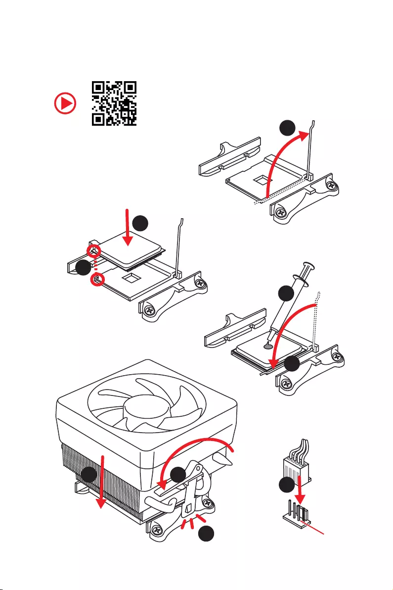
Installing a Processor/ Installation des Prozessors/ Installer un
processeur/ Установка процессора
1
2
3
6
4
5
7
89
CPU_FAN1
III
Quick Start
1
23
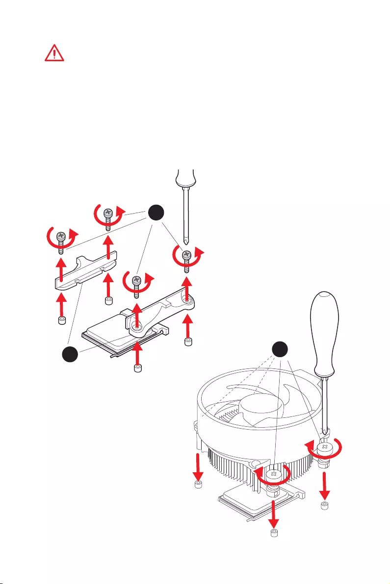
If you are installing the screw-type CPU heatsink, please follow the figure below
to remove the retention module first and then install the heatsink.
Wenn Sie einen CPU-Kühler mit Schraubenbefestigung einsetzen, folgen Sie bitte
den Anweisungen unten um das Retention-Modul zu entfernen und den Kühler zu
installieren.
Si vous voulez installer un ventirad pour processeur à vis, veuillez suivre les
instructions ci-dessous pour d’abord retirer le module de rétention puis installer le
ventirad.
В случае установки процессорного кулера с системой крепления на винтах,
следуйте указаниям на рисунке ниже для снятия пластикового модуля
крепления. Затем установите кулер.
IV Quick Start
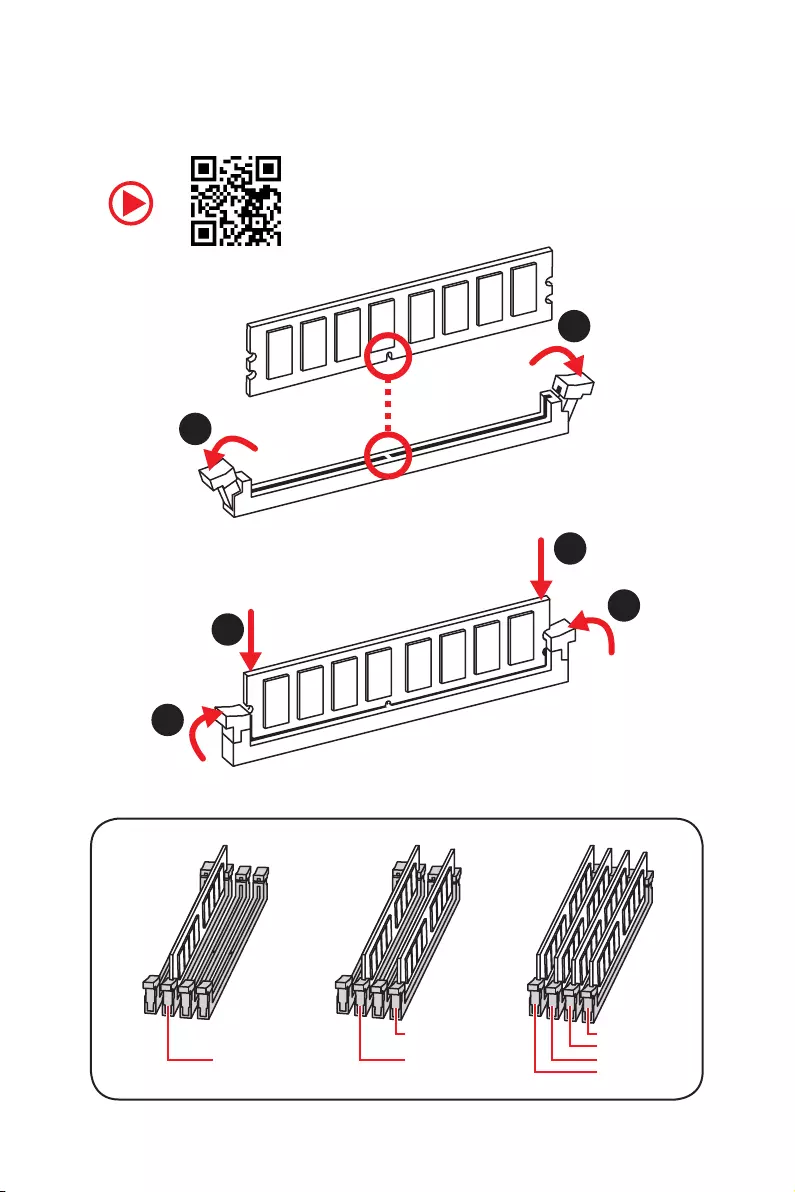
Installing DDR4 memory/ Installation des DDR4-Speichers/
Installer une mémoire DDR4/ Установка памяти DDR4
DIMMB2 DIMMB2
DIMMB1
DIMMA2 DIMMA2 DIMMA2
DIMMA1
1
1
2
2
3
3
V
Quick Start
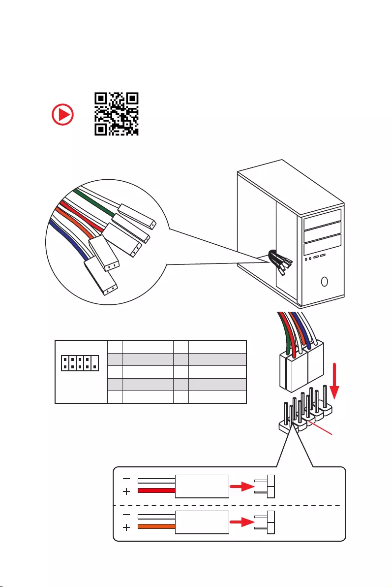
RESET SW
POWER SW
POWER LED+
POWER LED-
HDD LED
HDD LED
RESET SW
JFP1
HDD LED HDD LED —
HDD LED +
POWER LED —
POWER LED +
POWER LED
Connecting the Front Panel Header/ Anschließen der
Frontpanel-Stiftleiste/ Connecter un connecteur du panneau
avant/ Подключение разъемов передней панели
1
2 10
9
JFP1
1 HDD LED + 2 Power LED +
3 HDD LED — 4 Power LED —
5 Reset Switch 6 Power Switch
7 Reset Switch 8 Power Switch
9 Reserved 10 No Pin
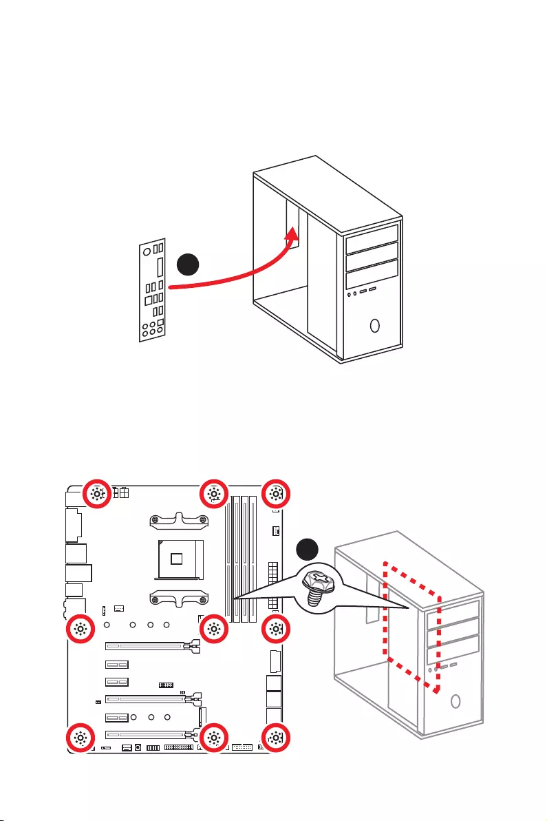
VI Quick Start
Installing the Motherboard/ Installation des Motherboards/
Installer la carte mère/ Установка материнской платы
1
2
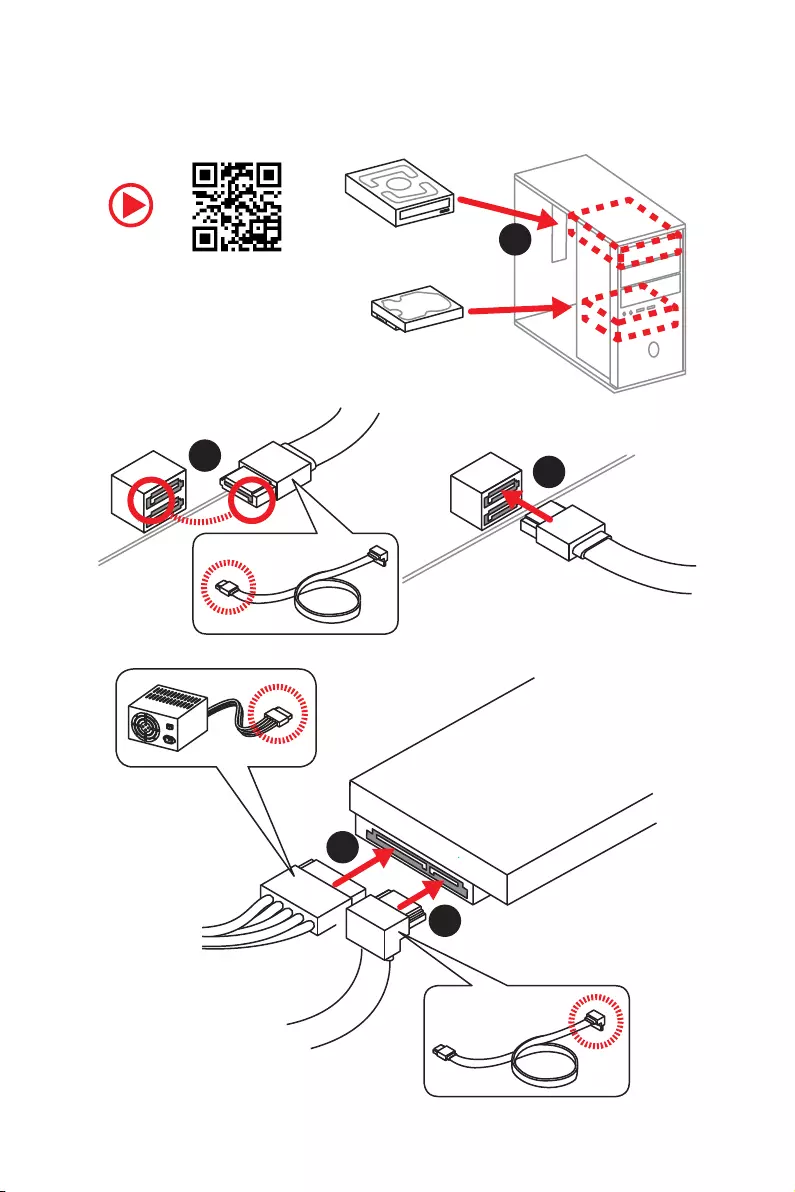
VII
Quick Start
1
23
4
5
Installing SATA Drives/ Installation der SATA-Laufwerke/
Installer le disque dur SATA/ Установка дисков SATA
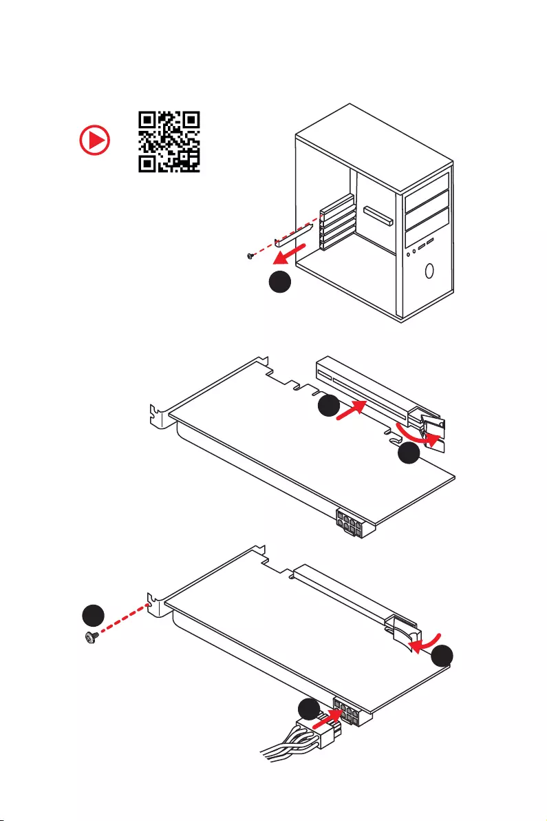
VIII Quick Start
1
2
3
4
5
6
Installing a Graphics Card/ Einbau der Grafikkarte/ Installer
une carte graphique/ Установка дискретной видеокарты
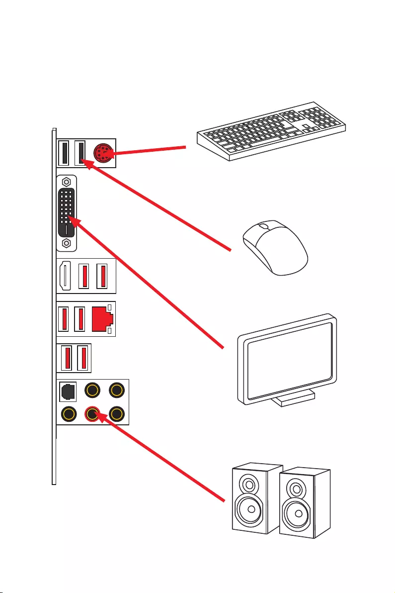
IX
Quick Start
Connecting Peripheral Devices/ Peripheriegeräte/
Connecter un périphérique anschliessen/ Подключение
периферийных устройств
Integrated Graphics Processing Unit (iGPU)
XQuick Start
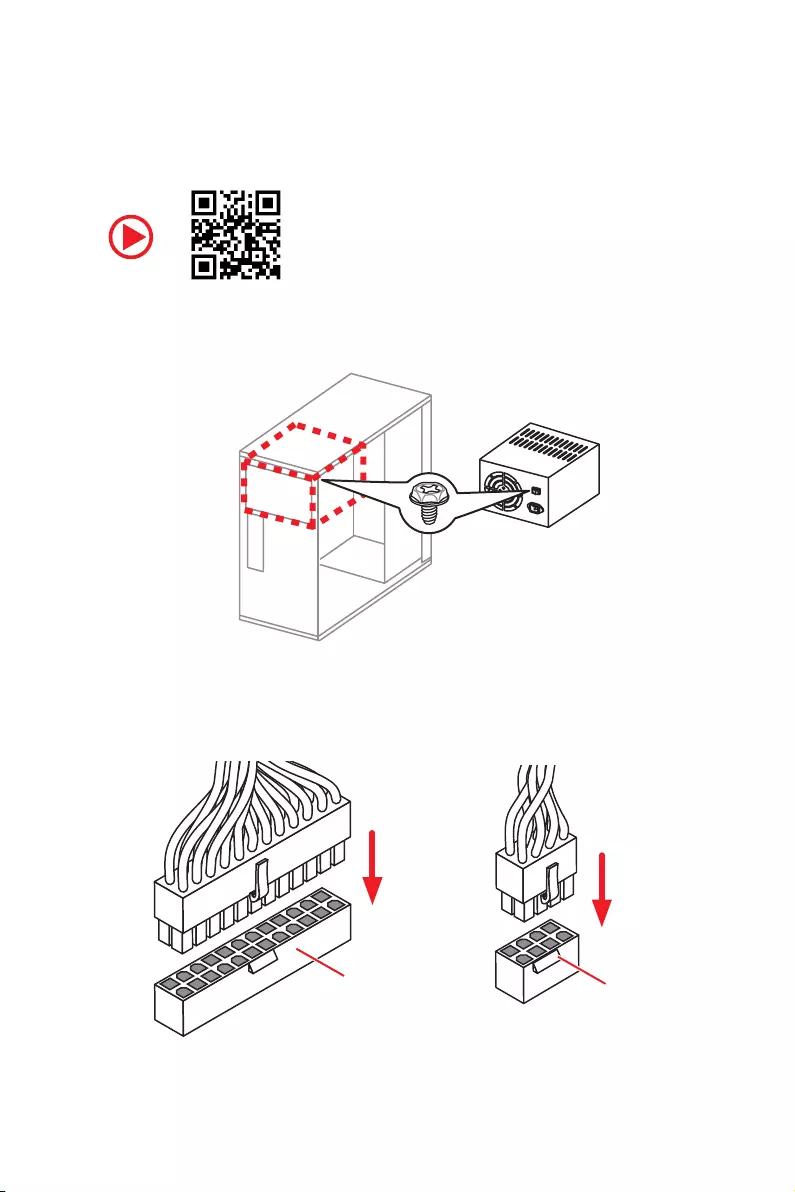
Connecting the Power Connectors/ Stromanschlüsse
anschliessen/ Connecter les câbles du module d’alimentation/
Подключение разъемов питания
ATX_PWR1 CPU_PWR1
XI
Quick Start
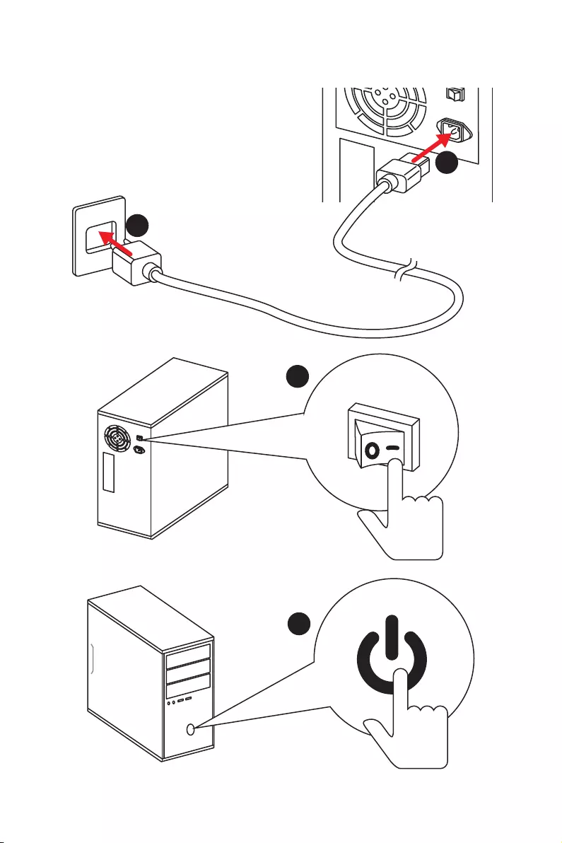
1
4
2
3
Power On/ Einschalten/ Mettre sous-tension/ Включение
питания

XII Quick Start
NOTE

1
Contents
Contents
Safety Information ……………………………………………………………………………………. 2
Specifications …………………………………………………………………………………………… 3
Rear I/O Panel ………………………………………………………………………………………….. 8
LAN Port LED Status Table…………………………………………………………………………. 8
Audio Ports Configuration ………………………………………………………………………….. 8
Realtek HD Audio Manager ………………………………………………………………………… 9
Overview of Components ………………………………………………………………………… 11
CPU Socket …………………………………………………………………………………………….. 12
DIMM Slots ……………………………………………………………………………………………… 13
PCI_E1~6: PCIe Expansion Slots ……………………………………………………………….. 14
M2_1~2: M.2 Slots (Key M) ……………………………………………………………………….. 16
SATA1~6: SATA 6Gb/s Connectors …………………………………………………………….. 17
JLPT1: Parallel Port Connector ………………………………………………………………… 17
CPU_PWR1, CPU_PWR2, ATX_PWR1: Power Connectors ……………………………. 18
JUSB1~2: USB 2.0 Connectors ………………………………………………………………….. 19
JUSB3~4: USB 3.2 Gen1 Connectors …………………………………………………………. 19
CPU_FAN1, PUMP_FAN1, SYS_FAN1~4: Fan Connectors …………………………….. 20
JAUD1: Front Audio Connector …………………………………………………………………. 21
JCI1: Chassis Intrusion Connector …………………………………………………………….. 21
JFP1, JFP2: Front Panel Connectors …………………………………………………………. 22
JTPM1: TPM Module Connector ………………………………………………………………… 22
JCOM1: Serial Port Connector ………………………………………………………………….. 23
JRGB1, JRGB2: RGB LED Connectors ……………………………………………………….. 23
JBAT1: Clear CMOS (Reset BIOS) Jumper ………………………………………………….. 24
CLR_CMOS1: Clear CMOS Button ……………………………………………………………… 24
BIOS Setup …………………………………………………………………………………………….. 25
Entering BIOS Setup ………………………………………………………………………………… 25
Resetting BIOS ………………………………………………………………………………………… 26
Updating BIOS …………………………………………………………………………………………. 26
EZ Mode …………………………………………………………………………………………………. 27
Advanced Mode ………………………………………………………………………………………. 29
OC Menu…………………………………………………………………………………………………. 30
Software Description ………………………………………………………………………………. 35
Installing Windows® 10 …………………………………………………………………………….. 35
Installing Drivers …………………………………………………………………………………….. 35
Installing Utilities ……………………………………………………………………………………. 35

2Safety Information
Safety Information
yThe components included in this package are prone to damage from electrostatic
discharge (ESD). Please adhere to the following instructions to ensure successful
computer assembly.
yEnsure that all components are securely connected. Loose connections may cause
the computer to not recognize a component or fail to start.
yHold the motherboard by the edges to avoid touching sensitive components.
yIt is recommended to wear an electrostatic discharge (ESD) wrist strap when
handling the motherboard to prevent electrostatic damage. If an ESD wrist strap is
not available, discharge yourself of static electricity by touching another metal object
before handling the motherboard.
yStore the motherboard in an electrostatic shielding container or on an anti-static pad
whenever the motherboard is not installed.
yBefore turning on the computer, ensure that there are no loose screws or metal
components on the motherboard or anywhere within the computer case.
yDo not boot the computer before installation is completed. This could cause
permanent damage to the components as well as injury to the user.
yIf you need help during any installation step, please consult a certified computer
technician.
yAlways turn off the power supply and unplug the power cord from the power outlet
before installing or removing any computer component.
yKeep this user guide for future reference.
yKeep this motherboard away from humidity.
yMake sure that your electrical outlet provides the same voltage as is indicated on the
PSU, before connecting the PSU to the electrical outlet.
yPlace the power cord such a way that people can not step on it. Do not place anything
over the power cord.
yAll cautions and warnings on the motherboard should be noted.
yIf any of the following situations arises, get the motherboard checked by service
personnel:
Liquid has penetrated into the computer.
The motherboard has been exposed to moisture.
The motherboard does not work well or you can not get it work according to user
guide.
The motherboard has been dropped and damaged.
The motherboard has obvious sign of breakage.
yDo not leave this motherboard in an environment above 60°C (140°F), it may damage
the motherboard.

3
Specifications
Specifications
CPU
Supports 1st, 2nd and 3rd Gen AMD Ryzen™/ Ryzen™ with
Radeon™ Vega Graphics and 2nd Gen AMD Ryzen™ with
Radeon™ Graphics/ Athlon™ with Radeon™ Vega Graphics
Desktop Processors for Socket AM4
Chipset AMD® X470 Chipset
Memory
y4x DDR4 memory slots, support up to 64GB
Supports DDR4 1866/ 2133/ 2400/ 2667 Mhz by JEDEC,
and 2667/ 2800/ 2933/ 3000/ 3066/ 3200/ 3466 Mhz by
A-XMP OC MODE*
yDual channel memory architecture
ySupports non-ECC UDIMM memory
ySupports ECC UDIMM memory
* Athlon™ with Radeon™ Vega Graphics processors support up to 2400 MHz. And
the supporting frequency of memory varies with installed processor. Please refer
www.msi.com for more information on compatible memory.
Expansion Slots
y2x PCIe 3.0 x16 slots (PCIE_1, PCIE_4)
1st, 2nd and 3rd Gen AMD Ryzen™ Processors support
x16/x0, x8/x8 mode
Ryzen™ with Radeon™ Vega Graphics and 2nd Gen AMD
Ryzen™ with Radeon™ Graphics Processors support x8/
x0 mode
Athlon™ with Radeon™ Vega Graphics Processors
support x4/x0 mode
y1x PCIe 2.0 x16 slot (PCIE_6, supports x4 mode)*
y3x PCIe 2.0 x1 slots
* PCI_E6 slot will be unavailable when installing M.2 PCIe SSD in M2_2 slot.
Onboard Graphics
y1x DVI-D port, supports a maximum resolution of
1920×1200@60Hz*
y1x HDMI™ port 1.4, supports a maximum resolution of
4096×2160@30Hz*
* Only support when using Ryzen™ with Radeon™ Vega Graphics and 2nd Gen
AMD Ryzen™ with Radeon™ Graphics/ Athlon™ with Radeon™ Vega Graphics
Processors
* Maximum shared memory of 2048 MB
Continued on next page

4Specifications
Continued from previous page
Multi-GPU
y1st, 2nd and 3rd Gen AMD Ryzen™ Processors
Supports 3-Way AMD® CrossFire™ Technology
yRyzen™ with Radeon™ Vega Graphics and 2nd Gen AMD
Ryzen™ with Radeon™ Graphics/ Athlon™ with Radeon™
Vega Graphics Processors
Supports 2-Way AMD® CrossFire™ Technology
LAN 1x Realtek® 8111H Gigabit LAN controller
Storage
y6x SATA 6Gb/s ports (from AMD® X470 Chipset)
y2x M.2 ports (Key M)*
M2_1 slot (from AMD® processor) supports PCIe
3.0×4 (1st, 2nd and 3rd Gen AMD Ryzen™/ Ryzen™ with
Radeon™ Vega Graphics and 2nd Gen AMD Ryzen™ with
Radeon™ Graphics Processors) or PCIe 3.0×2 (Athlon™
with Radeon™ Vega Graphics Processors) 2242/ 2260
/2280/ 22110 storage devices
M2_2 slot (from AMD® X470 Chipset) supports PCIe 2.0
x4 and SATA 6Gb/s 2242/ 2260 /2280 storage devices
* SATA1 port will be unavailable when installing SATA M.2 SSD in M2_2 slot.
* PCI_E6 slot will be unavailable when installing PCIe M.2 SSD in M2_2 slot.
RAID
AMD® X470 Chipset
ySupports RAID 0, RAID 1 and RAID 10 for SATA storage
devices
USB
yASMedia® ASM1143 Chipset
2x USB 3.2 Gen2 (SuperSpeed USB 10Gbps) Type-A
ports on the back panel
yAMD® X470 Chipset
4x USB 3.2 Gen1 (SuperSpeed USB) ports through the
internal USB connectors
6x USB 2.0 (High-speed USB) ports (2 Type-A ports on
the back panel, 4 ports available through the internal
USB connectors)
yAMD® CPU
4x USB 3.2 Gen1 (SuperSpeed USB) Type-A ports on the
back panel
Continued on next page

5
Specifications
Continued from previous page
Audio
yRealtek® ALC892 Codec
y7.1-Channel High Definition Audio
ySupports S/PDIF output
Back Panel
Connectors
y1x PS/2 keyboard/ mouse combo port
y2x USB 2.0 Type-A ports
y1x DVI-D port
y1x HDMI™ 1.4 port
y4x USB 3.2 Gen1 Type-A ports
y1x LAN (RJ45) port
y2x USB 3.2 Gen2 Type-A ports
y5x OFC audio jacks
y1x Optical S/PDIF OUT connector
Internal Connectors
y1x 24-pin ATX main power connector
y1x 8-pin ATX 12V power connector
y1x 4-pin ATX 12V power connector
y6x SATA 6Gb/s connectors
y2x USB 2.0 connectors (support additional 4 USB 2.0 ports)
y2x USB 3.2 Gen1 connectors (support additional 4 USB 3.2
Gen1 ports)
y1x 4-pin CPU fan connector
y1x 4-pin PUMP fan connector (supports up to 2A)
y4x 4-pin system fan connectors
y1x Serial port connector
y1x Parallel port connector
y2x 5050 RGB LED strip 12V connectors
y1x TPM module connector
y1x Front panel audio connector
y2x System panel connectors
y1x Chassis Intrusion connector
y1x Clear CMOS jumper
y1x Clear CMOS button
Continued on next page

6Specifications
Continued from previous page
I/O Controller NUVOTON NCT6795D Controller Chip
Hardware Monitor
yCPU/System temperature detection
yCPU/System fan speed detection
yCPU/System fan speed control
Form Factor yATX Form Factor
y12 in. x 9.6 in. (30.5 cm x 24.4 cm)
BIOS Features
y1x 256 Mb flash
yUEFI AMI BIOS
yACPI 6.1, SM BIOS 2.8
yMulti-language
Software
yDrivers
yAPP MANAGER
yCOMMAND CENTER
yLIVE UPDATE 6
yMYSTIC LIGHT
ySUPER CHARGER
yGAMING APP
yRAMDISK
yX-BOOST
ySMART TOOL
yNahimic Audio
yOpen Broadcaster Software (OBS)
yNorton™ Internet Security Solution
yGoogle Chrome™, Google Toolbar, Google Drive
yCPU-Z MSI GAMING
Continued on next page

7
Specifications
Continued from previous page
Special Features
yAudio
Audio Boost
Voice Boost
Nahimic 2.5
yStorage
Turbo M.2
yFan
Pump Fan
Smart Fan Control
yLED
Mystic Light
Mystic Light Extension
Mystic light SYNC
EZ DEBUG LED
yProtection
PCI-E Steel Armor
yPerformance
Multi GPU-CrossFire Technology
DDR4 Boost
GAME Boost
X-Boost
A-XMP
yStability
7000+ Quality Test
yVR
VR Ready
yGamer Experience
RAMDisk
yBIOS
Click BIOS 5
yCertification
GAMING Certified
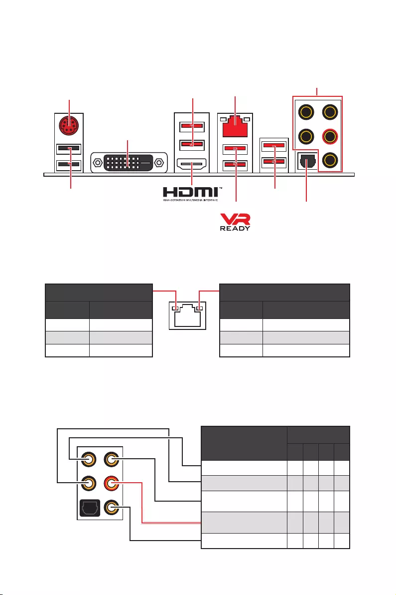
8Rear I/O Panel
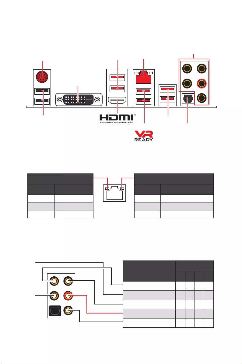
Audio Ports Configuration
Audio Ports Channel
2468
Center/ Subwoofer Out ● ●
Rear Speaker Out ●●●
Line-In/ Side Speaker Out ●
Line-Out/ Front Speaker Out ●●●●
Mic In
(●: connected, Blank: empty)
Rear I/O Panel
LAN
USB 2.0
PS/2
Audio Ports
Optical S/PDIF-Out
USB 3.2 Gen1
USB 3.2 Gen1
USB 3.2 Gen2
Link/ Activity LED
Status Description
Off No link
Yellow Linked
Blinking Data activity
Speed LED
Status Description
Off 10 Mbps connection
Green 100 Mbps connection
Orange 1 Gbps connection
LAN Port LED Status Table
DVI-D
9
Rear I/O Panel
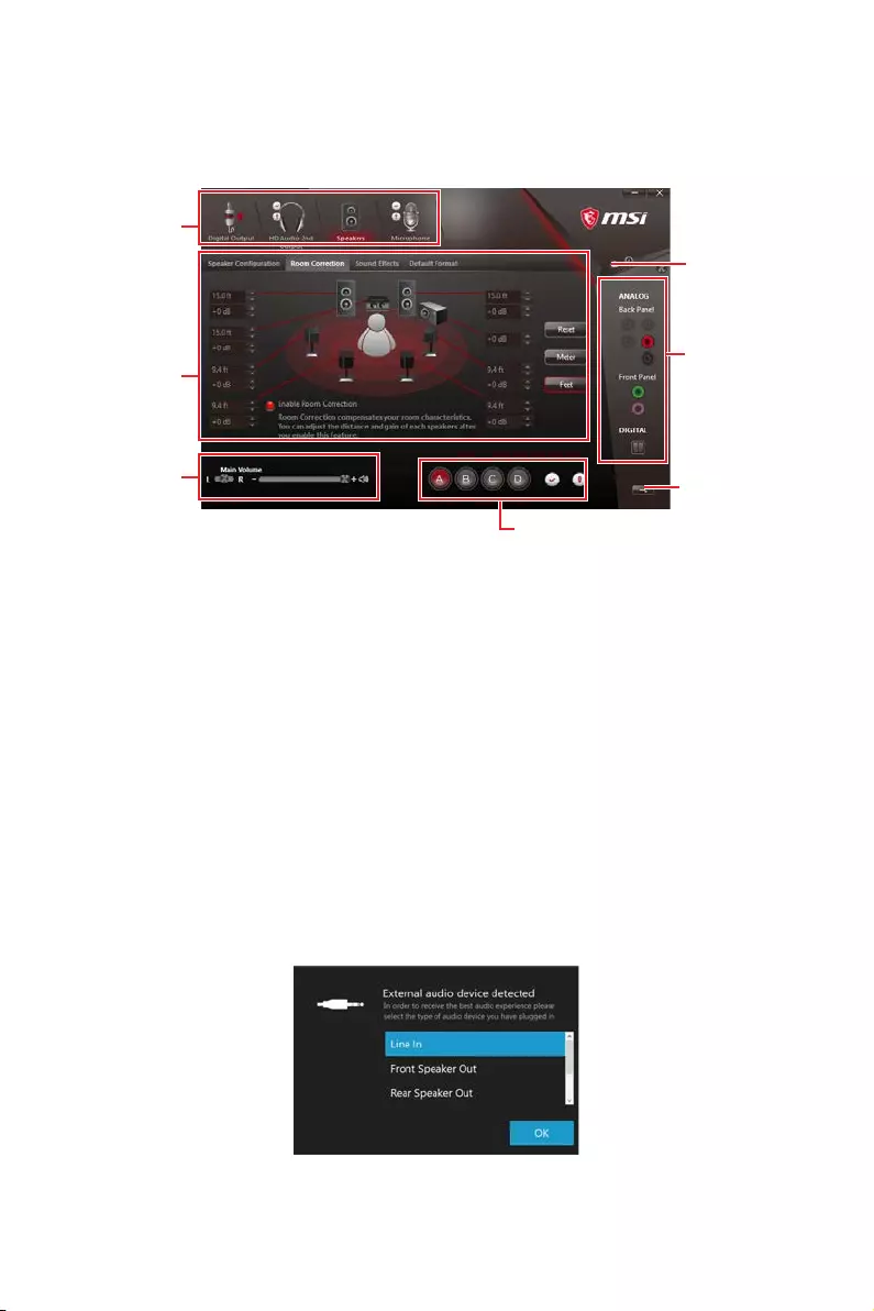
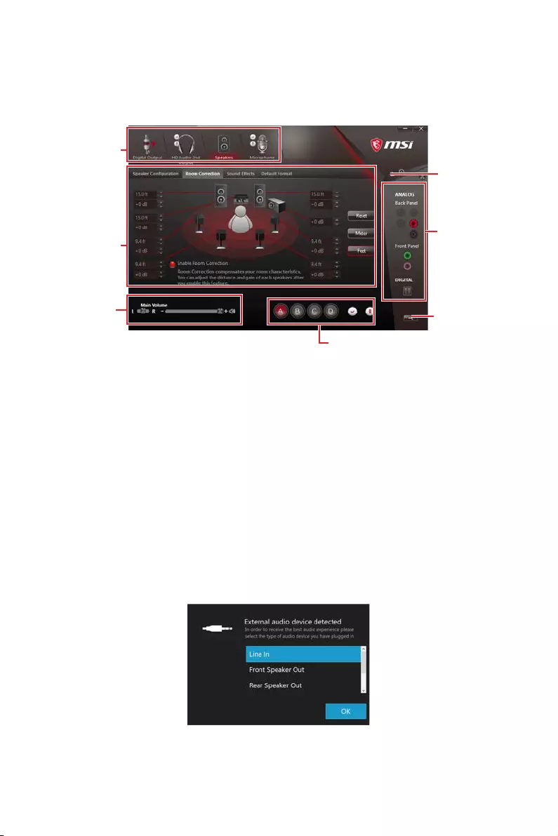
Realtek HD Audio Manager
After installing the Realtek HD Audio driver, the Realtek HD Audio Manager icon will
appear in the system tray. Double click on the icon to launch.
yDevice Selection — allows you to select a audio output source to change the related
options. The check sign indicates the devices as default.
yApplication Enhancement — the array of options will provide you a complete guidance
of anticipated sound effect for both output and input device.
yMain Volume — controls the volume or balance the right/left side of the speakers that
you plugged in front or rear panel by adjust the bar.
yProfiles — toggles between profiles.
yAdvanced Settings — provides the mechanism to deal with 2 independent audio
streams.
yJack Status — depicts all render and capture devices currently connected with your
computer.
yConnector Settings — configures the connection settings.
Auto popup dialog
When you plug into a device at an audio jack, a dialogue window will pop up asking you
which device is current connected.
Each jack corresponds to its default setting as shown on the next page.
Jack Status
Device
Selection
Connector
Settings
Profiles
Main Volume
Application
Enhancement
Advanced
Settings

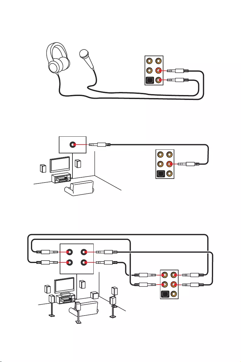
10 Rear I/O Panel
AUDIO INPUT
Rear Front
Side Center/
Subwoofer
Audio jacks to headphone and microphone diagram
Audio jacks to stereo speakers diagram
Audio jacks to 7.1-channel speakers diagram
AUDIO INPUT

11
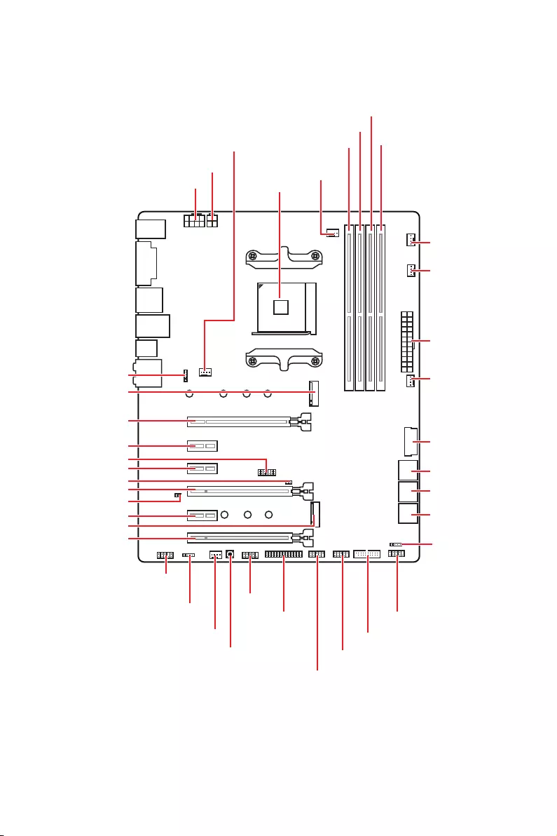
Overview of Components
Overview of Components
SATA▼3▲4
SATA▼1▲2
SATA▼5▲6
CPU_FAN1
JRGB1
JRGB2
PUMP_FAN1
PCI_E1
PCI_E2
PCI_E3
PCI_E4
PCI_E5
PCI_E6
JTPM1
CPU Socket
CPU_PWR1
CPU_PWR2
JBAT1
M2_2
M2_1
DIMMA1
SYS_FAN1
DIMMA2
DIMMB1
DIMMB2
JLPT1
JUSB1
JUSB2
JFP2
JFP1
JAUD1
ATX_PWR1
SYS_FAN3
SYS_FAN4
SYS_FAN2
Clear CMOS
JCOM1
JUSB4
JCI1
JUSB3

12 Overview of Components
CPU Socket
Introduction to the AM4 CPU
The surface of the AM4 CPU has a
yellow triangle to assist in correctly
lining up the CPU for motherboard
placement. The yellow triangle is
the Pin 1 indicator.
Important
y
When changing the processor, the system configuration could be cleared and reset
BIOS to default values, due to the AM4 processor’s architecture.
y
Always unplug the power cord from the power outlet before installing or removing
the CPU.
y
When installing a CPU, always remember to install a CPU heatsink. A CPU heatsink
is necessary to prevent overheating and maintain system stability.
y
Confirm that the CPU heatsink has formed a tight seal with the CPU before booting
your system.
y
Overheating can seriously damage the CPU and motherboard. Always make sure
the cooling fans work properly to protect the CPU from overheating. Be sure to apply
an even layer of thermal paste (or thermal tape) between the CPU and the heatsink to
enhance heat dissipation.
y
If you purchased a separate CPU and heatsink/ cooler, Please refer to the
documentation in the heatsink/ cooler package for more details about installation.
y
This motherboard is designed to support overclocking. Before attempting to
overclock, please make sure that all other system components can tolerate
overclocking. Any attempt to operate beyond product specifications is not
recommended. MSI
®
does not guarantee the damages or risks caused by inadequate
operation beyond product specifications.
53.43
mm
Distance from the center of the
CPU to the nearest DIMM slot.

13
Overview of Components
DIMM Slots
Important
y
Always insert memory modules in the DIMMA2 slot first.
y
Due to chipset resource usage, the available capacity of memory will be a little less
than the amount of installed.
y
Based on the processor specification, the Memory DIMM voltage below 1.35V is
suggested to protect the processor.
y
Some memory modules may operate at a lower frequency than the marked value
when overclocking due to the memory frequency operates dependent on its Serial
Presence Detect (SPD). Go to BIOS and find the DRAM Frequency to set the memory
frequency if you want to operate the memory at the marked or at a higher frequency.
y
It is recommended to use a more efficient memory cooling system for full DIMMs
installation or overclocking.
y
The stability and compatibility of installed memory module depend on installed CPU
and devices when overclocking.
y
Due to AM4 CPU/memory controller official specification limitation, the frequency of
memory modules may operate lower than the marked value under the default state.
Please refer www.msi.com for more information on compatible memory.
DIMMA1 DIMMB1
Channel A Channel B
DIMMA2 DIMMB2
Memory module installation recommendation
DIMMB2 DIMMB2
DIMMB1
DIMMA2 DIMMA2 DIMMA2
DIMMA1
14 Overview of Components
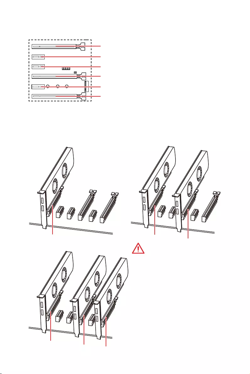
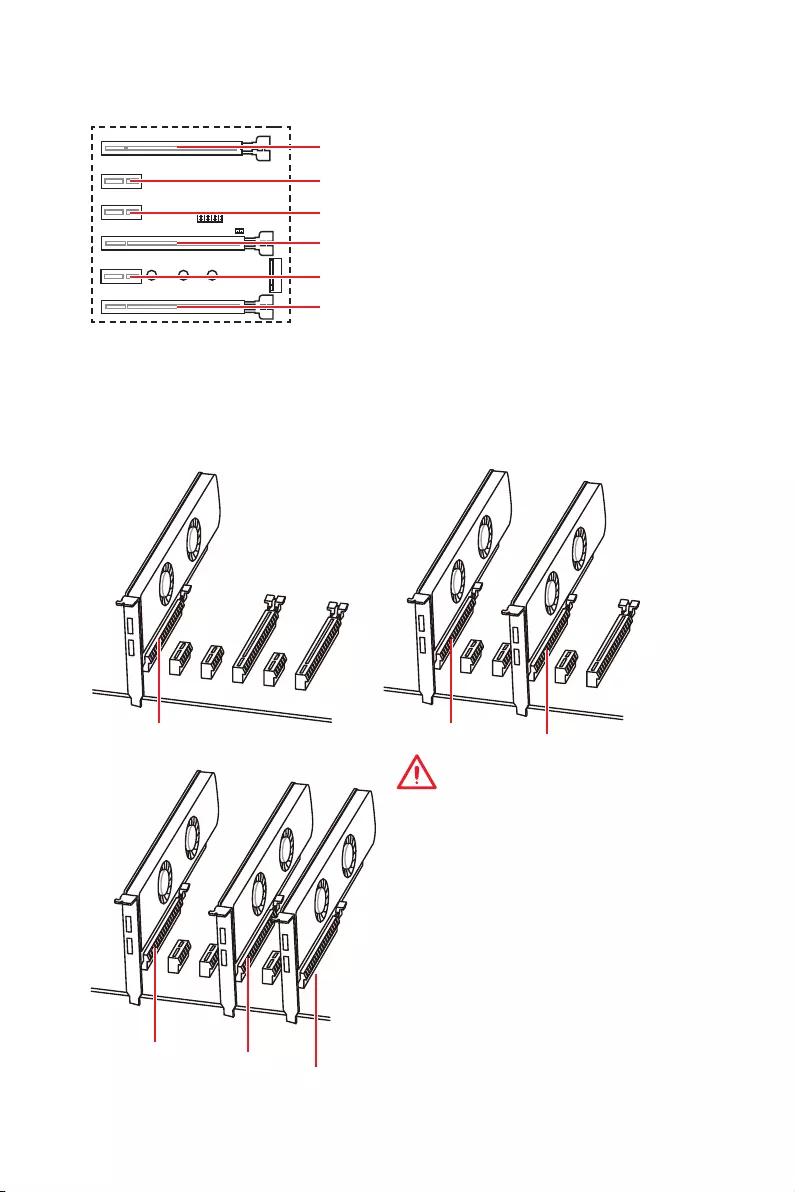
Multiple graphics cards installation recommendation (Ryzen™ series
processors)
x16 x8
x8
x8
x8 x4
Important
y
If you install a large and heavy
graphics card, you need to use a tool
such as MSI Gaming Series Graphics
Card Bolster to support its weight to
prevent deformation of the slot.
y
For a single PCIe x16 expansion card
installation with optimum performance,
using the PCI_E1 slot is recommended.
y
When adding or removing expansion
cards, always turn off the power supply
and unplug the power supply power
cable from the power outlet. Read the
expansion card’s documentation to
check for any necessary additional
hardware or software changes.
PCI_E4: PCIe 3.0 x8*/ Unavailable**/ Unavailable***
PCI_E1~6: PCIe Expansion Slots
PCI_E2: PCIe 2.0 x1
PCI_E3: PCIe 2.0 x1
PCI_E5: PCIe 2.0 x1
PCI_E6: PCIe 2.0 x4
PCI_E1: PCIe 3.0 x16*/ PCIe 3.0 x8**/ PCIe 3.0 x4***
* For 1st, 2nd and 3rd Gen AMD Ryzen™ Processors
** Ryzen™ with Radeon™ Vega Graphics and 2nd Gen AMD Ryzen™ with Radeon™
Graphics Processors
*** Athlon™ with Radeon™ Vega Graphics Processors
15
Overview of Components
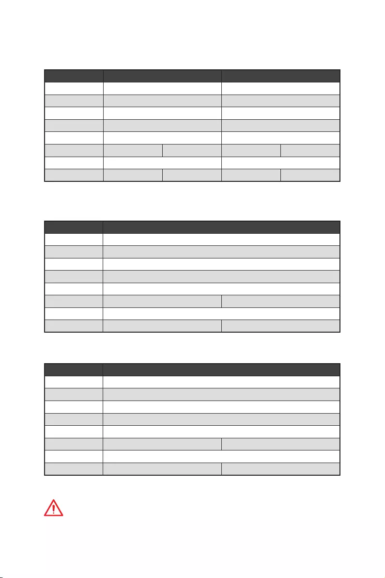
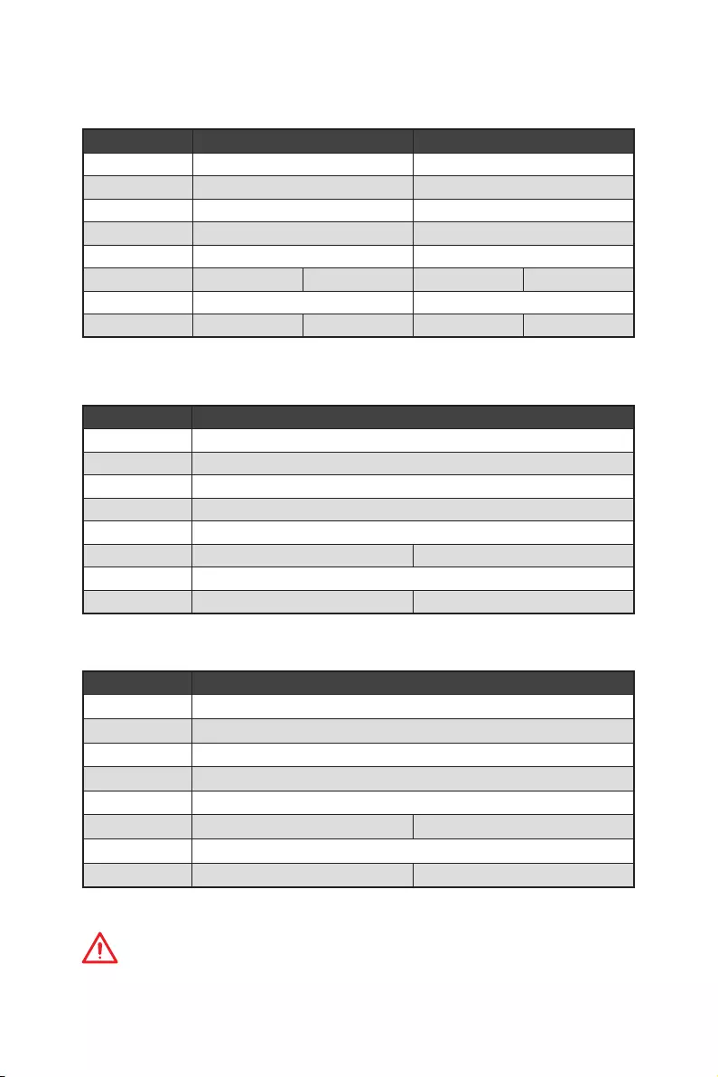
PCIe bandwidth table
For 1st, 2nd and 3rd Gen AMD Ryzen™ Processors
Slot Single 2-Way
PCI_E1 (CPU) Gen 3.0 x 16* Gen 3.0 x 8*
PCI_E2 (PCH) Gen 2.0 x 1 Gen 2.0 x 1
PCI_E3 (PCH) Gen 2.0 x 1 Gen 2.0 x 1
PCI_E4 (CPU) ─Gen 3.0 x 8*
PCI_E5 (PCH) Gen 2.0 x 1 Gen 2.0 x 1
PCI_E6 (PCH) Gen 2.0 x 4 ─Gen 2.0 x 4 ─
M2_1 (CPU) Gen 3.0 x 4 Gen 3.0 x 4
M2_2 (PCH) ─Gen 2.0 x 4 ─Gen 2.0 x 4
(─: unavailable, *: graphics card)
For Ryzen™ with Radeon™ Vega Graphics and 2nd Gen AMD Ryzen™ with Radeon™
Graphics Processors
Slot Single
PCI_E1 (CPU) Gen 3.0 x 8*
PCI_E2 (PCH) Gen 2.0 x 1
PCI_E3 (PCH) Gen 2.0 x 1
PCI_E4 (CPU) ─
PCI_E5 (PCH) Gen 2.0 x 1
PCI_E6 (PCH) Gen 2.0 x 4 ─
M2_1 (CPU) Gen 3.0 x 4
M2_2 (PCH) ─Gen 2.0 x 4
(─: unavailable, *: graphics card)
Athlon™ with Radeon™ Vega Graphics Processors
Slot Single
PCI_E1 (CPU) Gen 3.0 x 4*
PCI_E2 (PCH) Gen 2.0 x 1
PCI_E3 (PCH) Gen 2.0 x 1
PCI_E4 (CPU) ─
PCI_E5 (PCH) Gen 2.0 x 1
PCI_E6 (PCH) Gen 2.0 x 4 ─
M2_1 (CPU) Gen 3.0 x 2
M2_2 (PCH) ─Gen 2.0 x 4
(─: unavailable, *: graphics card)
Important
PCI_E6 slot will be unavailable when installing PCIe M.2 SSD in M2_2 slot.
16 Overview of Components
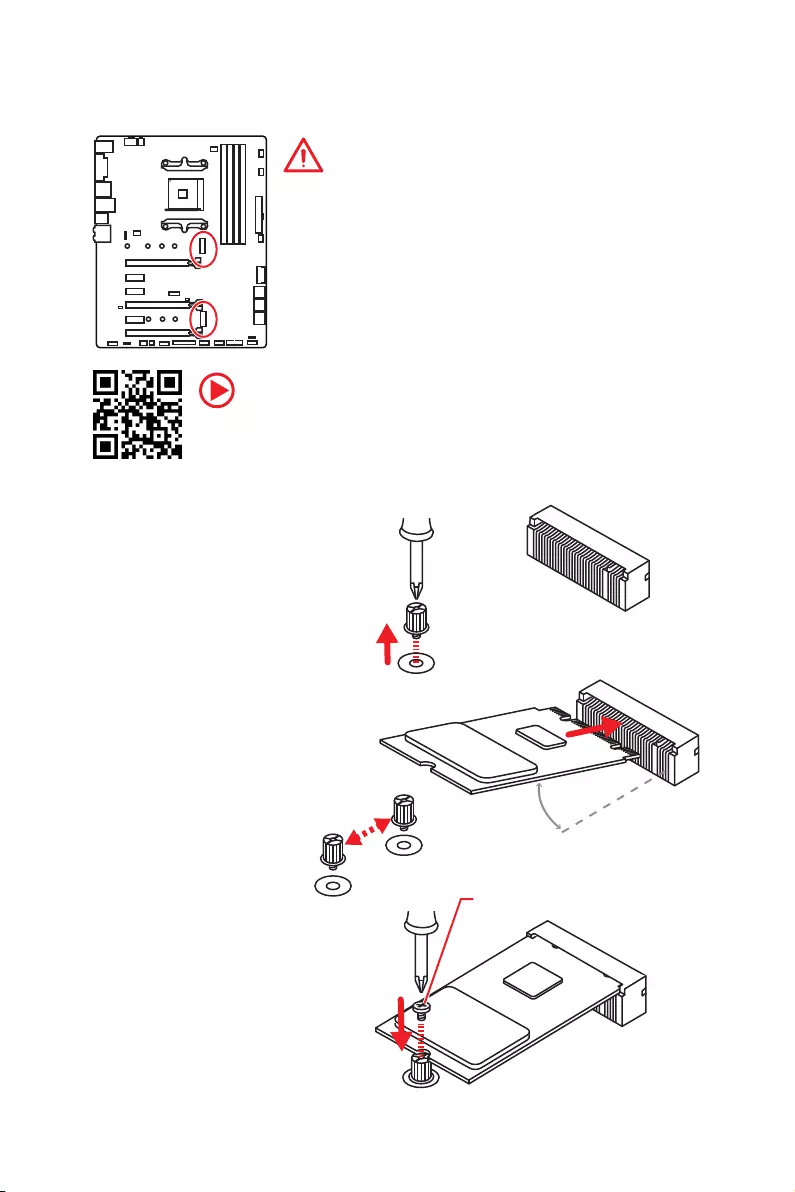
M2_1~2: M.2 Slots (Key M)
Video Demonstration
Watch the video to learn how to Install M.2 SSD.
http://youtu.be/JCTFABytrYA
Installing M.2 SSD
30°
2. Move and fasten the
M.2 riser screw to the
appropriate location
according your M.2 SSD
size.
3. Insert your M.2 SSD
into the M.2 slot at a
30-degree angle.
4. Secure the M.2 SSD in
place with the supplied
M.2 screw.
1. Loosen the M.2
riser screw from the
motherboard.
Supplied M.2 screw
Important
y
SATA1 port will be unavailable when installing SATA M.2
SSD in M2_2 slot.
y
PCI_E6 slot will be unavailable when installing PCIe M.2
SSD in M2_2 slot.
y
M2_1 slot only supports PCIe mode.
M2_1
M2_2
17
Overview of Components
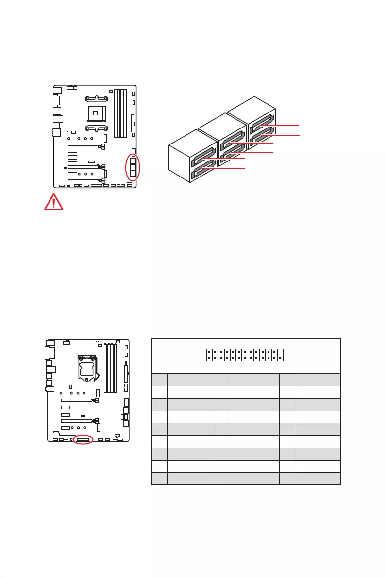
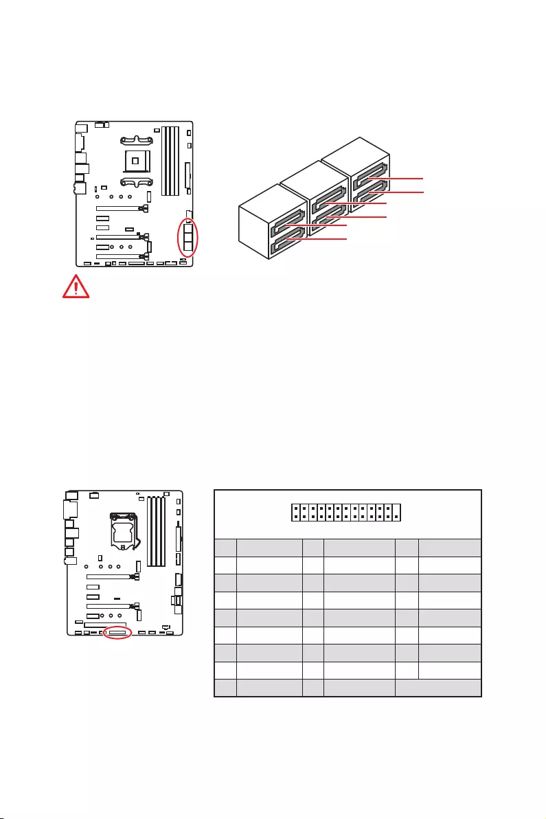
SATA1~6: SATA 6Gb/s Connectors
These connectors are SATA 6Gb/s interface ports. Each connector can connect to one
SATA device.
SATA5
SATA3
SATA1
SATA6
SATA4
SATA2
Important
y
SATA1 port will be unavailable when installing SATA M.2 SSD in M2_2 slot.
y
Please do not fold the SATA cable at a 90-degree angle. Data loss may result during
transmission otherwise.
y
SATA cables have identical plugs on either sides of the cable. However, it is
recommended that the flat connector be connected to the motherboard for space
saving purposes.
1
2 26
25
1 RSTB# 2 AFD# 3 PRND0
4 ERR# 5 PRND1 6 PINIT#
7 PRND2 8 LPT_SLIN# 9 PRND3
10 Ground 11 PRND4 12 Ground
13 PRND5 14 Ground 15 PRND6
16 Ground 17 PRND7 18 Ground
19 ACK# 20 Ground 21 BUSY
22 Ground 23 PE 24 Ground
25 SLCT 26 No Pin
JLPT1: Parallel Port Connector
This connector allows you to connect the optional parallel port with bracket.
18 Overview of Components
24
131
12
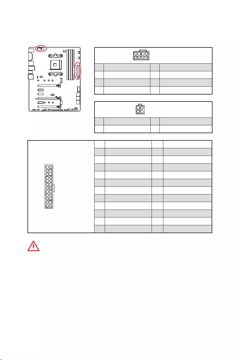
ATX_PWR1
1 +3.3V 13 +3.3V
2 +3.3V 14 -12V
3 Ground 15 Ground
4 +5V 16 PS-ON#
5 Ground 17 Ground
6 +5V 18 Ground
7 Ground 19 Ground
8 PWR OK 20 Res
9 5VSB 21 +5V
10 +12V 22 +5V
11 +12V 23 +5V
12 +3.3V 24 Ground
5
4 1
8CPU_PWR1
1 Ground 5 +12V
2 Ground 6 +12V
3 Ground 7 +12V
4 Ground 8 +12V
Important
Make sure that all the power cables are securely connected to a proper ATX power
supply to ensure stable operation of the motherboard.
CPU_PWR1, CPU_PWR2, ATX_PWR1: Power Connectors
These connectors allow you to connect an ATX power supply.
3
2 1
4CPU_PWR2
1 Ground 3 +12V
2 Ground 4 +12V

19
Overview of Components
JUSB3~4: USB 3.2 Gen1 Connectors
These connectors allow you to connect USB 3.2 Gen1 ports on the front panel.
Important
Note that the Power and
Ground pins must be
connected correctly to avoid
possible damage.
1 10
1120
JUSB3
1
10 11
20
JUSB4
1Power 11 USB2.0+
2 USB3_RX_DN 12 USB2.0-
3 USB3_RX_DP 13 Ground
4 Ground 14 USB3_TX_C_DP
5 USB3_TX_C_DN 15 USB3_TX_C_DN
6 USB3_TX_C_DP 16 Ground
7 Ground 17 USB3_RX_DP
8 USB2.0- 18 USB3_RX_DN
9 USB2.0+ 19 Power
10 NC 20 No Pin
JUSB1~2: USB 2.0 Connectors
These connectors allow you to connect USB 2.0 ports on the front panel.
1
2 10
9
1VCC 2VCC
3 USB0- 4 USB1-
5 USB0+ 6 USB1+
7 Ground 8 Ground
9 No Pin 10 NC
Important
y
Note that the VCC and Ground pins must be connected correctly to avoid possible
damage.
y
In order to recharge your iPad,iPhone and iPod through USB ports, please install
MSI
®
SUPER CHARGER utility.
20 Overview of Components
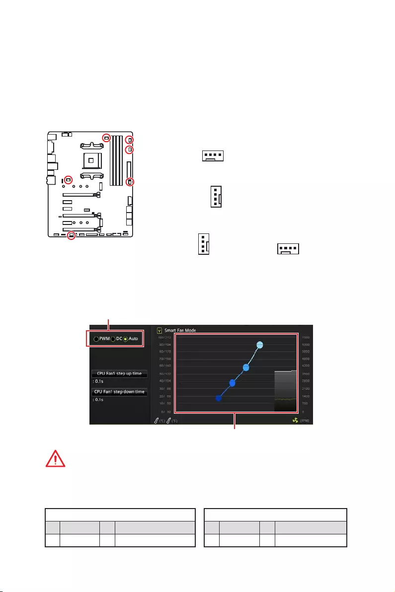
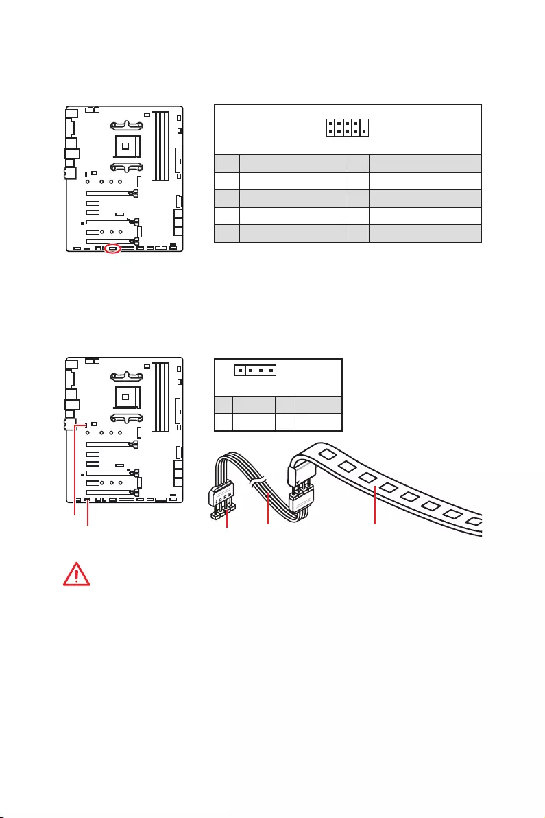
CPU_FAN1, PUMP_FAN1, SYS_FAN1~4: Fan Connectors
Fan connectors can be classified as PWM (Pulse Width Modulation) Mode or DC
Mode. PWM Mode fan connectors provide constant 12V output and adjust fan speed
with speed control signal. DC Mode fan connectors control fan speed by changing
voltage. When you plug a 3-pin (Non-PWM) fan to a fan connector in PWM mode, the
fan speed will always maintain at 100%, which might create a lot of noise. CPU_FAN1
and PUMP_FAN1 can automatically detect PWM and DC mode. You can follow the
instruction below to adjust the fan connector to PWM or DC Mode.
PWM Mode pin definition
1 Ground 2 +12V
3 Sense 4 Speed Control Signal
DC Mode pin definition
1 Ground 2 Voltage Control
3 Sense 4 NC
Default PWM Mode fan connector
Default DC Mode fan connectors
Switching fan mode and adjusting fan speed
You can switch between PWM mode and DC mode and adjust fan speed in BIOS >
HARDWARE MONITOR.
Select PWM ,DC or Auto mode
Important
Make sure fans are working properly after switching the PWM/ DC mode.
There are gradient points of the fan speed that allow you to adjust
fan speed in relation to CPU temperature.
1
SYS_FAN1/ SYS_FAN3/ SYS_FAN4
1
SYS_FAN2
1
CPU_FAN1
Pin definition of fan connectors
Default Auto Mode fan connector
1
PUMP_FAN1
21
Overview of Components
JAUD1: Front Audio Connector
This connector allows you to connect audio jacks on the front panel.
1
2 10
9
1 MIC L 2 Ground
3 MIC R 4 NC
5 Head Phone R 6 MIC Detection
7 SENSE_SEND 8 No Pin
9 Head Phone L 10 Head Phone Detection
JCI1: Chassis Intrusion Connector
This connector allows you to connect the chassis intrusion switch cable.
Normal
(default)
Trigger the chassis
intrusion event
Using chassis intrusion detector
1. Connect the JCI1 connector to the chassis intrusion switch/ sensor on the chassis.
2. Close the chassis cover.
3. Go to BIOS > Settings > Security > Chassis Intrusion Configuration.
4. Set Chassis Intrusion to Enabled.
5. Press F10 to save and exit and then press the Enter key to select Yes.
6. Once the chassis cover is opened again, a warning message will be displayed on
screen when the computer is turned on.
Resetting the chassis intrusion warning
1. Go to BIOS > Settings > Security > Chassis Intrusion Configuration.
2. Set Chassis Intrusion to Reset.
3. Press F10 to save and exit and then press the Enter key to select Yes.
22 Overview of Components
1
2 14
13
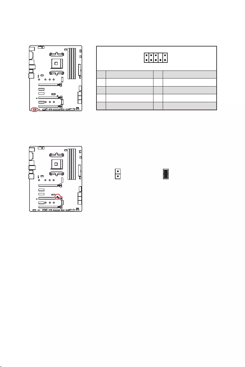
1 LPC Clock 2 3V Standby power
3 LPC Reset 4 3.3V Power
5 LPC address & data pin0 6 Serial IRQ
7 LPC address & data pin1 8 5V Power
9 LPC address & data pin2 10 No Pin
11 LPC address & data pin3 12 Ground
13 LPC Frame 14 Ground
JTPM1: TPM Module Connector
This connector is for TPM (Trusted Platform Module). Please refer to the TPM security
platform manual for more details and usages.
JFP1, JFP2: Front Panel Connectors
These connectors connect to the switches and LEDs on the front panel.
1
2 10
9
JFP1
1 HDD LED + 2 Power LED +
3 HDD LED — 4 Power LED —
5 Reset Switch 6 Power Switch
7 Reset Switch 8 Power Switch
9 Reserved 10 No Pin
1
JFP2
1 Speaker — 2 Buzzer +
3 Buzzer — 4 Speaker +
23
Overview of Components
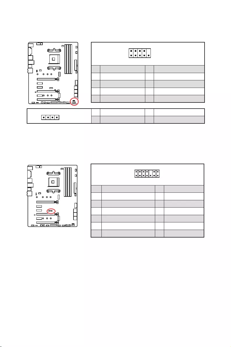
JRGB1, JRGB2: RGB LED Connectors
The JRGB1/JRGB2 connector allows you to connect the 5050 RGB LED strips 12V and
AMD CPU cooler with RGB LED.
Important
y
The JRGB1/JRGB2 connector supports 5050 RGB LED strips (12V/G/R/B) with the
maximum power rating of 3A (12V).
y
Please keeping the LED strip shorter than 2 meters to prevent dimming.
y
Always turn off the power supply and unplug the power cord from the power outlet
before installing or removing the RGB LED strip.
y
Please use MSI’s software to control the extended LED strip.
1
JRGB1/
JRGB2
JRGB1
JRGB2 Extension cable 5050 RGB LED strips 12V
1
JRGB1
JRGB2
1 +12V 2 G
3 R 4 B
1
2 10
9
1 DCD 2 SIN
3 SOUT 4 DTR
5 Ground 6 DSR
7 RTS 8 CTS
9 RI 10 No Pin
JCOM1: Serial Port Connector
This connector allows you to connect the optional serial port with bracket.

24 Overview of Components
JBAT1: Clear CMOS (Reset BIOS) Jumper
There is CMOS memory onboard that is external powered from a battery located on
the motherboard to save system configuration data. If you want to clear the system
configuration, set the jumpers to clear the CMOS memory.
Keep Data
(default)
Clear CMOS/
Reset BIOS
Resetting BIOS to default values
1. Power off the computer and unplug the power cord.
2. Use a jumper cap to short JBAT1 for about 5-10 seconds.
3. Remove the jumper cap from JBAT1.
4. Plug the power cord and power on the computer.
CLR_CMOS1: Clear CMOS Button
Power off your computer. Press and hold the Clear CMOS button for about 5-10
seconds to reset BIOS to default values.
Clear CMOS button

25
BIOS Setup
BIOS Setup
The default settings offer the optimal performance for system stability in normal
conditions. You should always keep the default settings to avoid possible system
damage or failure booting unless you are familiar with BIOS.
Important
y
BIOS items are continuously update for better system performance. Therefore, the
description may be slightly different from the latest BIOS and should be for reference
only. You could also refer to the HELP information panel for BIOS item description.
y
The pictures in this chapter are for reference only and may vary from the product you
purchased.
Entering BIOS Setup
Press Delete key, when the Press DEL key to enter Setup Menu, F11 to enter Boot
Menu message appears on the screen during the boot process.
Function key
F1: General Help
F2: Add/ Remove a favorite item
F3: Enter Favorites menu
F4: Enter CPU Specifications menu
F5: Enter Memory-Z menu
F6: Load optimized defaults
F7: Switch between Advanced mode and EZ mode
F8: Load Overclocking Profile
F9: Save Overclocking Profile
F10: Save Change and Reset*
F12: Take a screenshot and save it to USB flash drive (FAT/ FAT32 format only).
Ctrl+F: Enter Search page
* When you press F10, a confirmation window appears and it provides the modification
information. Select between Yes or No to confirm your choice.

26 BIOS Setup
Resetting BIOS
You might need to restore the default BIOS setting to solve certain problems. There are
several ways to reset BIOS:
yGo to BIOS and press F6 to load optimized defaults.
yShort the Clear CMOS jumper on the motherboard.
Important
Be sure the computer is off before clearing CMOS data. Please refer to the Clear
CMOS jumper section for resetting BIOS.
Updating BIOS
Updating BIOS with M-FLASH
Before updating:
Please download the latest BIOS file that matches your motherboard model from MSI
website. And then save the BIOS file into the USB flash drive.
Updating BIOS:
1. Insert the USB flash drive that contains the update file into the computer.
2. Press <Ctrl+F5> key during POST.
3. Click on Yes to reboot the system and enter the flash mode.
4. Select a BIOS file to perform the BIOS update process.
5. After the flashing process is 100% completed, the system will reboot
automatically.
Updating the BIOS with Live Update 6
Before updating:
Make sure the LAN driver is already installed and the Internet connection is set
properly.
Updating BIOS:
1. Install and launch MSI LIVE UPDATE 6.
2. Select BIOS Update.
3. Click on Scan button.
4. Click on Download icon to download and install the latest BIOS file.
5. Click Next and choose In Windows mode. And then click Next and Start to start
updating BIOS.
6. After the flashing process is 100% completed, the system will restart
automatically.
27
BIOS Setup
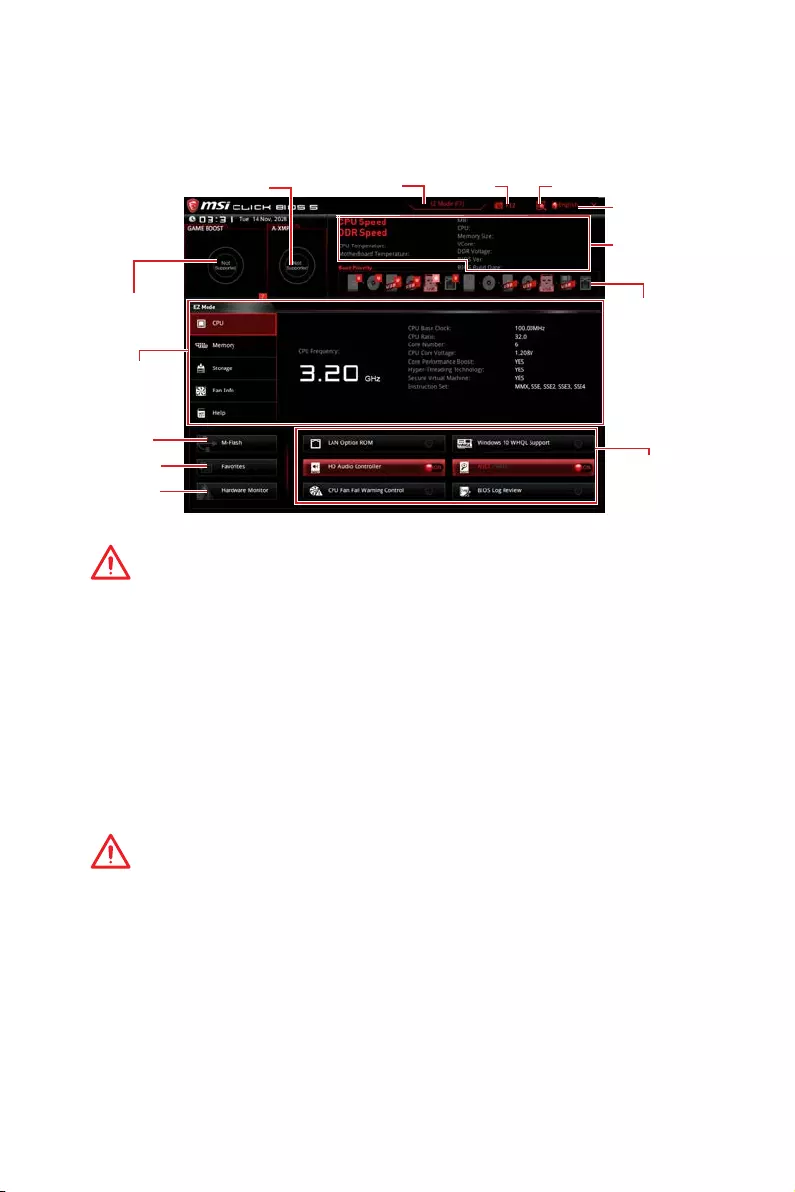
EZ Mode
At EZ mode, it provides the basic system information and allows you to configure the
basic setting. To configure the advanced BIOS settings, please enter the Advanced
Mode by pressing the Setup Mode switch or F7 function key.
Information
display
System
information
Boot device
priority bar
Function
buttons
Language
Search
ScreenshotSetup Mode switch
M-Flash
Favorites
Hardware
Monitor
GAME BOOST
switch
A-XMP switch
yGAME BOOST switch — click on it to toggle the GAME BOOST for OC.
Important
Please don’t make any changes in OC menu and don’t load defaults to keep the
optimal performance and system stability after activating the GAME Boost function.
yA-XMP switch (optional) — click on the inner circle to enable/ disable the A-XMP.
Switch the outer circle to select the memory profile if any. This switch will only be
available if the installed processor and memory modules support this function.
ySetup Mode switch — press this tab or the F7 key to switch between Advanced mode
and EZ mode.
yScreenshot — click on this tab or the F12 key to take a screenshot and save it to USB
flash drive (FAT/ FAT32 format only).
ySearch — click on this tab or the Ctrl+F keys and the search page will show. It allows
you to search by BIOS item name, enter the item name to find the item listing. Move
the mouse over a blank space and right click the mouse to exit search page.
Important
In search page, only the F6, F10 and F12 function keys are available.
yLanguage — allows you to select the language of BIOS setup.
ySystem information — shows the CPU/ DDR speed, CPU/ MB temperature, MB/ CPU
type, memory size, CPU/ DDR voltage, BIOS version and build date.
yBoot device priority bar — you can move the device icons to change the boot priority.
The boot priority from high to low is left to right.

28 BIOS Setup
yInformation display — click on the CPU, Memory, Storage, Fan Info and Help buttons
on left side to display related information.
yFunction buttons — enable or disable the LAN Option ROM, HD audio controller,
Window 10 WHQL Support, AHCI, RAID, CPU Fan Fail Warning Control and BIOS Log
Review by clicking on their respective button.
Important
y
During windows setup, the RAID driver may be required and you can find the RAID
driver in MSI Driver Disc.
y
You can use MSI SMART TOOL to build the Windows
®
installation drive that includes
RAID driver.
y
If your system currently boots to M.2 SSD RAID and you delete the RAID volume in
the UEFI BIOS, your system will become un-bootable.
yM-Flash — click on this button to display the M-Flash menu that provides the way to
update BIOS with a USB flash drive.
yHardware Monitor — click on this button to display the Hardware Monitor menu that
allows you to manually control the fan speed by percentage.
yFavorites — press the Favorites tab or the F3 key to enter Favorites menu. It allows
you to create personal BIOS menu where you can save and access favorite/ frequently-
used BIOS setting items.
Default HomePage — allows you to select a BIOS menu (e.g. SETTINGS, OC…,etc)
as the BIOS home page.
Favorite1~5 — allows you to add the frequently-used/ favorite BIOS setting items
in one page.
To add a BIOS item to a favorite page (Favorite 1~5)
1. Move the mouse over a BIOS item not only on BIOS menu but also on search
page.
2. Right-click or press F2 key.
3. Choose a favorite page and click on OK.
To delete a BIOS item from favorite page
1. Move the mouse over a BIOS item on favorite page (Favorite 1~5)
2. Right-click or press F2 key.
3. Choose Delete and click on OK.
29
BIOS Setup
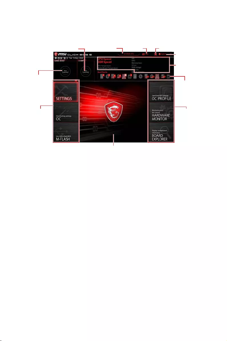
Advanced Mode
Press Setup Mode switch or F7 function key can switch between EZ Mode and
Advanced Mode in BIOS setup.
A-XMP switch
GAME BOOST
switch
System
information
Boot device
priority bar
BIOS menu
selection
Language
SearchScreenshotSetup Mode switch
Menu display
BIOS menu
selection
yGAME BOOST switch/ Setup Mode switch/ Screenshot/ Favorites/ Language/
System information/ Boot device priority bar — please refer to the descriptions of EZ
Mode Overview section.
yBIOS menu selection — the following options are available:
SETTINGS — allows you to specify the parameters for chipset and boot devices.
OC — allows you to adjust the frequency and voltage. Increasing the frequency may
get better performance.
M-FLASH — provides the way to update BIOS with a USB flash drive.
OC PROFILE — allows you to manage overclocking profiles.
HARDWARE MONITOR — allows you to set the speeds of fans and monitor voltages
of system.
BOARD EXPLORER — provides the information of installed devices on this
motherboard.
yMenu display — provides BIOS setting items and information to be configured.
30 BIOS Setup
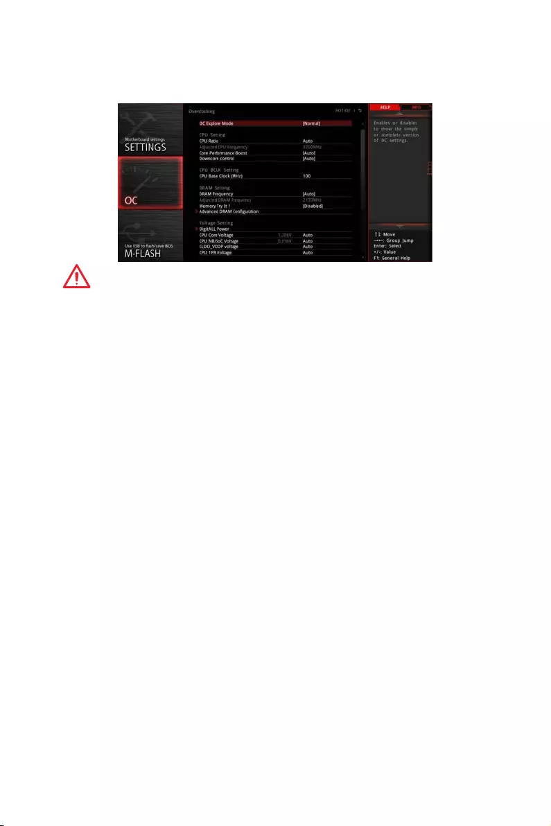
OC Menu
This menu is for advanced users who want to overclock the motherboard.
Important
y
Overclocking your PC manually is only recommended for advanced users.
y
Overclocking is not guaranteed, and if done improperly, it could void your warranty or
severely damage your hardware.
y
If you are unfamiliar with overclocking, we advise you to use GAME BOOST function
for easy overclocking.
y
The BIOS items in OC menu will vary with the processor.
fOC Explore Mode [Normal]
Enables or disables to show the normal or expert version of OC settings.
[Normal] Provides the regular OC settings in BIOS setup.
[Expert] Provides the advanced OC settings for OC expert to configure in BIOS
setup.
Note: We use * as the symbol for the OC settings of Expert mode.
fCPU Ratio [Auto]
Sets the CPU ratio that is used to determine CPU clock speed. This item can only be
changed if the processor supports this function.
fCore Performance Boost [Auto]
Enables or disables the Core Performance Boost (CPB). This item appears when the
installed CPU supports this function.
fDowncore Control [Auto] (optional)
Sets the number of processor cores to be used. This item appears when the installed
CPU supports this function.
fA-XMP [Disabled]
Please enable A-XMP or select a profile of memory module for overclocking the
memory. This item will be available when the installed memory modules, processor
and motherboard support this function.
fDRAM Frequency [Auto]
Sets the DRAM frequency. Please note the overclocking behavior is not guaranteed.

31
BIOS Setup
fMemory Try It ! [Disabled]
It can improve memory compatibility or performance by choosing optimized memory
preset.
fMemory Retry Count [5]
Sets counts for memory OC retrying. When memory OC has failed, setting this item
as [5] will allow system to reboot 5 times with the same overclocked configuration. If
overclocking has failed every time, the system will restore the defaults.
fAdvanced DRAM Configuration (optional)
Press Enter to enter the sub-menu. User can set the memory timing for each/ all
memory channel. The system may become unstable or unbootable after changing
memory timing. If it occurs, please clear the CMOS data and restore the default
settings. (Refer to the Clear CMOS jumper/ button (optional) section to clear the CMOS
data, and enter the BIOS to load the default settings.)
fDigitALL Power
Press Enter to enter the sub-menu. Controls the digital powers related to CPU PWM.
fCPU Loadline Calibration Control [Auto]
The CPU voltage will decrease proportionally according to CPU loading. Higher
load-line calibration could get higher voltage and good overclocking performance,
but increase the temperature of the CPU and VRM. If set to Auto, BIOS will
configure this setting automatically.
fCPU Over Voltage Protection [Auto]
Sets the voltage limit for CPU over-voltage protection. If set to Auto, BIOS will
configure this setting automatically. Higher voltage provides less protection and
may damage the system.
fCPU Under Voltage Protection [Auto]
Sets the voltage limit for CPU under-voltage protection. If set to Auto, BIOS will
configure this setting automatically. Higher voltage provides less protection and
may damage the system.
fCPU Over Current Protection [Auto]
Sets the current limit for CPU over-current protection. If set to Auto, BIOS will
configure this setting 0utomatically.
[Auto] This setting will be configured automatically by BIOS.
[Enhanced] Extends the current range for over-current protection.
fCPU Switching Frequency [Auto]
Sets the PWM working speed to stabilize CPU Core voltage and minimize ripple
range. Increasing the PWM working speed will cause higher temperature of
MOSFET. So please make sure a cooling solution is well-prepared for MOSFET
before you increase the value. If set to Auto, BIOS will configure this setting
automatically.
fCPU VRM Over Temperature Protection [Auto]
Sets the temperature limit on CPU VRM for over-temperature protection. The CPU
frequency may be throttled when CPU temperature over the specified temperature.
If set to Auto, BIOS will configure this settings.

32 BIOS Setup
fCPU Power Duty Control [Thermal Balance]
Sets the current of every VRM phase and the thermal conditions of every phase
component.
[Thermal Balance] Maintains the VRM thermal balance.
[Current Balance] Maintains the current VRM balance.
fCPU NB Loadline Calibration Control [Auto]
The CPU-NB voltage will decrease proportionally according to CPU-NB loading.
Higher load-line calibration could get higher voltage and good overclocking
performance, but increase the temperature. If set to Auto, BIOS will configure this
setting automatically.
fCPU NB Over Current Protection [Auto]
Sets the current limit for CPU-NB over-current protection. If set to Auto, BIOS will
configure this setting 0utomatically.
[Auto] This setting will be configured automatically by BIOS.
[Enhanced] Extends the current range for over-current protection.
fCPU NB Switching Frequency [Auto]
Sets the PWM working speed to stabilize CPU-NB voltage and minimize ripple
range. Increasing the PWM working speed will cause higher temperature of
MOSFET. So please make sure a cooling solution is well-prepared for MOSFET
before you increase the value. If set to Auto, BIOS will configure this setting
automatically.
fCPU NB Power Duty Control [Thermal Balance]
Sets the current of CPU-NB VRM phase and the thermal conditions of every phase
component.
[Thermal Balance] Maintains the VRM thermal balance.
[Current Balance] Maintains the current VRM balance.
fVR 12VIN OCP Expander [Auto]
Expands the limitation of VR Over Current Protection with 12V input voltage. The
higher expanding value indicates less protection. Therefore, please adjust the
current carefully if needed, or it may damage the CPU/ VR MOS. If set to «Auto»,
BIOS will configure this setting automatically.
fCPU Voltages control [Auto]
These options allows you to set the voltages related to CPU. If set to Auto, BIOS will
set these voltages automatically or you can set it manually.
fDRAM Voltages control [Auto]
These options allows you to set the voltages related to memory. If set to Auto, BIOS
will set these voltages automatically or you can set it manually.
fMemory Changed Detect [Enabled]*
Enables or disables the system to issue a warning message during boot when the
memory has been replaced.
[Enabled] The system will issue a warning message during boot and then you have
to load the default settings for new devices.
[Disabled] Disables this function and keeps the current BIOS settings.
fCPU Specifications

33
BIOS Setup
Press Enter to enter the sub-menu. This sub-menu displays the information of
installed CPU. You can also access this information menu at any time by pressing [F4].
Read only.
fCPU Technology Support
Press Enter to enter the sub-menu. The sub-menu shows the key features of
installed CPU. Read only.
fMEMORY-Z
Press Enter to enter the sub-menu. This sub-menu displays all the settings and
timings of installed memory. You can also access this information menu at any time by
pressing [F5].
fDIMMx Memory SPD
Press Enter to enter the sub-menu. The sub-menu displays the information of
installed memory. Read only.
fCPU Features
Press Enter to enter the sub-menu.
fSimultaneous Multi-Threading [Enabled] (optional)
Enables/ disables the AMD Simultaneous Multi-Threading. This item appears when
the installed CPU supports this technology.
fGlobal C-state Control [Enabled] (optional)
Enables/ disables IO based C-state generation and DF C-states.
fOpcache Control [Auto] (optional)
Enables/ disables Opcache. Opcache stores recently decode instruction to save
the decoding time when the instruction is repeated. And ist may increase the CPU
performance and reduce the power consumption slightly.
fIOMMU Mode (optional)
Enables/disables the IOMMU (I/O Memory Management Unit) for I/O Virtualization.
fSpread Spectrum (optional)
This function reduces the EMI (Electromagnetic Interference) generated by
modulating clock generator pulses.
[Enabled] Enables the spread spectrum function to reduce the EMI
(Electromagnetic Interference) problem.
[Disabled] Enhances the overclocking ability of CPU Base clock.
Important
y
If you do not have any EMI problem, leave the setting at [Disabled] for optimal system
stability and performance. But if you are plagued by EMI, select the value of Spread
Spectrum for EMI reduction.
y
The greater the Spread Spectrum value is, the greater the EMI is reduced, and the
system will become less stable. For the most suitable Spread Spectrum value, please
consult your local EMI regulation.
y
Remember to disable Spread Spectrum if you are overclocking because even a
slight jitter can introduce a temporary boost in clock speed which may just cause your
overclocked processor to lock up.

34 BIOS Setup
fRelaxed EDC throttling [Auto] (optional)
Relaxed EDC throttling reduces the amount of time the processor will throttle the
cores.
[Auto] AMD’s recommendation
[Enabled] Reduce the amount of time the processor will throttle.
[Disabled] Part-specific EDC throttling protection enabled.
fAMD Cool’n’Quiet [Enabled]
The Cool’n’Quiet technology can effectively and dynamically lower CPU speed and
power consumption.
fSVM Mode [Disabled]
Enables/ disables the AMD SVM (Secure Virtual Machine) Mode.
fBIOS PSP Support [Enabled] (optional)
Enables/ disables the BIOS PSP support. It manages PSP sub-item including all
C2P/P2C mailbox, Secure S3, fTPM support.
fPower Supply Idle Control [Auto] (optional)
It allows you to select the power-saving control mode for CPU when all cores are in
a non-CO state. If set to Auto, BIOS will configure this settings.

35
Software Description
Software Description
Installing Windows® 10
1. Power on the computer.
2. Insert the Windows® 10 disc into your optical drive.
3. Press the Restart button on the computer case.
4. Press F11 key during the computer POST (Power-On Self Test) to get into Boot
Menu.
5. Select your optical drive from the Boot Menu.
6. Press any key when screen shows Press any key to boot from CD or DVD…
message.
7. Follow the instructions on the screen to install Windows® 10.
Installing Drivers
1. Start up your computer in Windows® 10.
2. Insert MSI® Driver Disc into your optical drive.
3. The installer will automatically appear and it will find and list all necessary
drivers.
4. Click Install button.
5. The software installation will then be in progress, after it has finished it will
prompt you to restart.
6. Click OK button to finish.
7. Restart your computer.
Installing Utilities
Before you install utilities, you must complete drivers installation.
1. Insert MSI® Driver Disc into your optical drive.
2. The installer will automatically appear.
3. Click Utilities tab.
4. Select the utilities you want to install.
5. Click Install button.
6. The utilities installation will then be in progress, after it has finished it will prompt
you to restart.
7. Click OK button to finish.
8. Restart your computer.

36 Software Description
NOTE

1
Inhalt
Inhalt
Sicherheitshinweis …………………………………………………………………………………… 2
Spezifikationen ………………………………………………………………………………………… 3
Rückseite E/A ………………………………………………………………………………………….. 8
LAN Port LED Zustandstabelle …………………………………………………………………… 8
Konfiguration der Audioanschlüsse …………………………………………………………….. 8
Realtek HD Audio Manager ………………………………………………………………………… 9
Übersicht der Komponenten ……………………………………………………………………. 11
CPU Sockel …………………………………………………………………………………………….. 12
DIMM Steckplätze ……………………………………………………………………………………. 13
PCI_E1~6: PCIe Erweiterungssteckplätze ………………………………………………….. 14
M2_1~2: M.2 Steckplätze (Key M) ……………………………………………………………… 16
SATA1~6: SATA 6Gb/s Anschlüsse ……………………………………………………………… 17
JLPT1: Parallele Schnittstelle …………………………………………………………………… 17
CPU_PWR1, CPU_PWR2, ATX_PWR1: Stromanschlüsse ……………………………… 18
JUSB1~2: USB 2.0 Anschlüsse ………………………………………………………………….. 19
JUSB3~4: USB 3.2 Gen1 Anschlüsse …………………………………………………………. 19
CPU_FAN1, PUMP_FAN1, SYS_FAN1~4: Stromanschlüsse für Lüfter …………… 20
JAUD1: Audioanschluss des Frontpanels …………………………………………………… 21
JCI1: Gehäusekontaktanschluss ……………………………………………………………….. 21
JFP1, JFP2: Frontpanel-Anschlüsse ………………………………………………………….. 22
JTPM1: TPM Anschluss ……………………………………………………………………………. 22
JCOM1: Serieller Anschluss ……………………………………………………………………… 23
JRGB1, JRGB2: RGB LED Anschlüsse ……………………………………………………….. 23
JBAT1: Clear CMOS Steckbrücke (Reset BIOS) …………………………………………… 24
CLR_CMOS1: Clear CMOS Taste ……………………………………………………………….. 24
BIOS Setup …………………………………………………………………………………………….. 25
Öffnen des BIOS Setups……………………………………………………………………………. 25
Reset des BIOS ……………………………………………………………………………………….. 26
Aktualisierung des BIOS …………………………………………………………………………… 26
EZ Modus ……………………………………………………………………………………………….. 27
Erweiterter Modus ………………………………………………………………………………….. 29
OC Menü…………………………………………………………………………………………………. 30
Softwarebeschreibung ……………………………………………………………………………. 35
Installation von Windows® 10 ……………………………………………………………………. 35
Installation von Treibern …………………………………………………………………………… 35
Installation von Utilities ……………………………………………………………………………. 35

2Sicherheitshinweis
Sicherheitshinweis
yDie im Paket enthaltene Komponenten sind der Beschädigung durch
elektrostatischen Entladung (ESD). Beachten Sie bitte die folgenden Hinweise, um die
erfolgreichen Computermontage sicherzustellen.
yStellen Sie sicher, dass alle Komponenten fest angeschlossen sind. Lockere
Steckverbindungen können Probleme verursachen, zum Beispiel: Der Computer
erkennt eine Komponente nicht oder startet nicht.
yHalten Sie das Motherboard nur an den Rändern fest, und verhindern Sie die
Berührung der sensiblen Komponenten.
yUm eine Beschädigung der Komponenten durch elektrostatische Entladung (ESD) zu
vermeiden, sollten Sie eines elektrostatischen Armbands während der Handhabung
des Motherboards tragen. Wenn kein elektrostatischen Handgelenkband vorhanden
ist, sollten Sie Ihre statische Elektrizität ableiten, indem Sie ein anderes Metallobjekt
berühren, bevor Sie das Motherboard anfassen.
yBewahren Sie das Motherboard in einer elektrostatische Abschirmung oder einem
Antistatiktuch auf, wenn das Motherboard nicht installiert ist.
yÜberprüfen Sie vor dem Einschalten des Computers, dass sich keine losen
Schrauben und andere Bauteile auf dem Motherboard oder im Computergehäuse
befinden.
yBitte starten Sie den Computer nicht, bevor die Installation abgeschlossen ist. Dies
könnte permanente Schäden an den Komponenten sowie zu das Verletzung des
Benutzers verursachen.
ySollten Sie Hilfe bei der Installation benötigen, wenden Sie sich bitte an einen
zertifizierten Computer-Techniker.
ySchalten Sie die Stromversorgung aus und ziehen Sie das das Stromkabel ab, bevor
Sie jegliche Computer-Komponente ein- und ausbauen.
yBewahren Sie die Bedienungsanleitung als künftige Referenz auf.
yHalten Sie das Motherboard von Feuchtigkeit fern.
yBitte stellen Sie sicher, dass Ihre Netzspannung den Hinweisen auf dem Netzteil vor
Anschluss des Netzteils an die Steckdose entspricht.
yVerlegen Sie das Netzkabel so, dass niemand versehentlich darauf treten kann.
Stellen Sie nichts auf dem Netzkabel ab.
yAlle Achtungs- und Warnhinweise auf dem Motherboard müssen befolgt werden.
yFalls einer der folgenden Umstände eintritt, lassen Sie bitte das Motherboard von
Kundendienstpersonal prüfen:
Flüssigkeit ist in dem Computer eingedrungen.
Das Motherboard wurde Feuchtigkeit ausgesetzt.
Das Motherboard funktioniert nicht richtig oder Sie können es nicht wie in der
Bedienungsanleitung beschrieben bedienen.
Das Motherboard ist heruntergefallen und beschädigt.
Das Motherboard weist offensichtlich Zeichen eines Schadens auf.
yNutzen und lagern Sie das Gerät nicht an Stellen, an denen Temperaturen von mehr
als 60°C herrschen — das Motherboard kann in diesem Fall Schaden nehmen.

3
Spezifikationen
Spezifikationen
CPU
Unterstützt die AMD Ryzen™ der 1., 2. und 3. Generation
Prozessoren/ Ryzen™ Prozessoren mit Radeon™ Vega
Grafikprozessor und AMD Ryzen™ der 2. Generation
Prozessoren mit Radeon™ Grafikprozessor/ Athlon™
Prozessoren mit Radeon™ Vega-Grafik-Desktop-Prozessoren
für Sockel AM4
Chipsatz AMD® X470 Chipsatz
Speicher
y4x DDR4 Speicherplätze, aufrüstbar bis 64 GB
Unterstützt DDR4 1866/ 2133/ 2400/ 2667 Mhz durch
JEDEC, und 2667/ 2800/ 2933/ 3000/ 3066/ 3200/ 3466
Mhz durch A-XMP OC MODE*
yDual-Kanal-Speicherarchitektur
yUnterstützt non-ECC UDIMM-Speicher
yUnterstützt ECC UDIMM-Speicher
*Athlon™ Prozessoren mit Radeon™ Vega-Grafikprozessor unterstützen bis
zu 2400 MHz. Die unterstützende Frequenz des Speichers ist unterschiedlich
je nach dem installierten Prozessor. Weitere Informationen zu kompatiblen
Speicher finden Sie unter: http://www.msi.com.
Erweiterung-
anschlüsse
y2x PCIe 3.0 x16-Steckplätze (PCIE_1, PCIE_4)
AMD Ryzen™ der 1., 2. und 3. Generation Prozessoren
unterstützen x16/x0, x8/x8 Modus
Ryzen™ Prozessoren mit Radeon™ Vega Grafikprozessor
und AMD Ryzen™ der 2. Generation Prozessoren mit
Radeon™ Grafikprozessor unterstützen x8/x0 Modus
Athlon™ Prozessoren mit Radeon™ Vega Grafikprozessor
unterstützen den x4/x0 Modus
y1x PCIe 2.0 x16-Steckplatz (PCIE_6, unterstützt den x4
Modus)*
y3x PCIe 2.0 x1-Steckplätze
* Der PCI_E6 Steckplatz wird nicht zur Verfügung, wenn Sie eine M.2 PCIe SSD
im M2_2-Steckplatz installieren.
Onboard-Grafik
y1x DVI-D Anschluss, Unterstützung einer maximalen
Auflösung von 1920×1200@60Hz*
y1x HDMI™ 1.4 Anschluss, Unterstützung einer maximalen
Auflösung von 4096×2160@30Hz*
* Diese Funktion wird nur bei der Verwendung von AMD® Ryzen™ Prozessoren mit
Radeon™ Vega Grafikprozessor und AMD Ryzen™ der 2. Generation Prozessoren
mit Radeon™ Grafikprozessor/Athlon™ Prozessoren mit Radeon™ Vega
Grafikprozessor unterstützt.
* Die Größe des gemeinsamen Speichers ist auf 2048 MB begrenzt.
Fortsetzung auf der nächsten Seite

4Spezifikationen
Fortsetzung der vorherigen Seite
Multi-GPU
yAMD Ryzen™ der 1., 2. und 3. Generation Prozessoren
Unterstützt die 3-Wege AMD® CrossFire™ Technologie
yAMD Ryzen™ der 2. Generation Prozessoren mit Radeon™
Grafikprozessor/Athlon™ Prozessoren mit Radeon™ Vega
Grafikprozessor
Unterstützt die 2-Wege AMD® CrossFire™ Technologie
LAN 1x Realtek® 8111H Gigabit LAN Controller
Aufbewahrung
y6x SATA 6Gb/s Anschlüsse (aus dem AMD® X470 Chipsatz)
y2x M.2 Anschlüsse (Key M)*
M2_1 Steckplatz (aus dem AMD® Prozessor) unterstützt
PCIe 3.0 x4 (AMD Ryzen™ der 1., 2. und 3. Generation
Prozessoren/ Ryzen™ Prozessoren mit Radeon™ Vega
Grafikprozessor und AMD Ryzen™ der 2. Generation
Prozessoren mit Radeon™ Grafikprozessor) oder
PCIe 3.0 x2 (Athlon™ Prozessoren mit Radeon™ Vega
Grafikprozessor) 2242/ 2260 /2280/ 22110 Speichergeräte
M2_2 Steckplatz (aus dem AMD® X470 Chipsatz)
unterstützt PCIe 2.0 x4 und SATA 6Gb/s 2242/ 2260 /2280
Speichergeräte
* Der SATA1 Steckplatz wird nicht zur Verfügung stehen, wenn Sie eine SATA M.2
SSD im M2_2 Steckplatz installieren.
* Der PCI_E6 Steckplatz wird nicht zur Verfügung stehen, wenn Sie eine PCIe M.2
SSD im M2_2 Steckplatz installieren.
RAID
AMD® X470 Chipsatz
yUnterstützt RAID 0, RAID 1 und RAID 10 für SATA
Speichergeräte
USB
yASMedia® ASM1143 Chipsatz
2x USB 3.2 Gen2 (SuperSpeed USB 10Gbps) Typ-A
Anschlüsse an der rückseitigen Anschlussleiste
yAMD® X470 Chipsatz
4x USB 3.2 Gen1 (SuperSpeed USB) Anschlüsse stehen
durch die internen USB Anschluss zur Verfügung
6x USB 2.0 (High-speed USB) ports (2 Typ-A Anschlüsse
an der rückseitigen Anschlussleiste, 4 Anschlüsse stehen
durch die internen USB Anschluss zur Verfügung)
yAMD® CPU
4x USB 3.2 Gen1 (SuperSpeed USB) Typ-A Anschlüsse
an der rückseitigen Anschlussleiste
Fortsetzung auf der nächsten Seite

5
Spezifikationen
Fortsetzung der vorherigen Seite
Audio
yRealtek® ALC892 Codec
y7.1-Kanal-HD-Audio
yUnterstützt S/PDIF-Ausgang
Hintere Ein-/ und
Ausgänge
y1x PS/2 Tastatur/ Maus-Combo-Anschluss
y2x USB 2.0 Typ-A Anschlüsse
y1x DVI-D Anschluss
y1x HDMI™ 1.4 Anschluss
y4x USB 3.2 Gen1 Typ-A Anschlüsse
y1x LAN (RJ45) Anschluss
y2x USB 3.2 Gen2 Typ-A Anschlüsse
y5x OFC Audiobuchsen
y1x Optischer S/PDIF-Ausgang
Interne Anschlüsse
y1x 24-poliger ATX Stromanschluss
y1x 8-poliger ATX 12 V Stromanschluss
y1x 4-poliger ATX 12 V Stromanschluss
y6x SATA 6Gb/s Anschlüsse
y2x USB 2.0 Anschlüsse (unterstützt zusätzliche 4 USB 2.0
-Ports)
y2x USB 3.1 Gen1 Anschlüsse (unterstützt zusätzliche 4
USB 3.2 Gen1-Ports)
y1x 4-poliger CPU-Lüfter-Anschluss
y1x 4-poliger PUMP-Lüfter-Anschluss (unterstützt bis zu
2A)
y4x 4-polige System-Lüfter-Anschlüsse
y1x Serieller Anschluss
y1x Parallele Schnittstelle
y2x 5050 RGB LED Streifen 12V Anschlüsse
y1x TPM Anschluss
y1x Audioanschluss des Frontpanels
y2x System-Panel-Anschlüsse
y1x Gehäusekontaktschalter
y1x Clear CMOS Steckbrücke
y1x Clear CMOS Taste
Fortsetzung auf der nächsten Seite

6Spezifikationen
Fortsetzung der vorherigen Seite
E/A Anschluss NUVOTON NCT6795D Controller Chip
Hardware Monitor
yCPU/System Temperaturerfassung
yCPU/System Geschwindigkeitserfassung
yCPU/System Lüfterdrehzahlregelung
Fromfaktor yATX Fromfaktor
y12 Zoll x 9,6 Zoll (30,5 cm x 24,4 cm)
BIOS Funktionen
y1x 128 Mb Flash
yUEFI AMI BIOS
yACPI 6.1, SM BIOS 2.8
yMehrsprachenunterstützung
Software
yTreiber
yAPP MANAGER
yCOMMAND CENTER
yLIVE UPDATE 6
yMYSTIC LIGHT
ySUPER CHARGER
yGAMING APP
yRAMDISK
yX-BOOST
ySMART TOOL
yNahimic Audio
yOpen Broadcaster Software (OBS)
yNorton™ Internet Security Solution
yGoogle Chrome™, Google Toolbar, Google Drive
yCPU-Z MSI GAMING
Fortsetzung auf der nächsten Seite

7
Spezifikationen
Fortsetzung der vorherigen Seite
Besondere
Funktionen
yAudio
Audio Boost
Voice Boost
Nahimic 2.5
ySpeicherung
Turbo M.2
yLüfter
Pump-Lüfter
Smart-Lüftersteuerung
yLED
Mystic Light
Mystic Light Extension
Mystic Light SYNC
EZ DEBUG LED
ySchutz
PCI-E Steel Armor
yLeistung
Multi GPU-CrossFire Technologie
DDR4 Boost
GAME Boost
X-Boost
A-XMP
yStabilität
7000+ Quality Test
yVR
VR Ready
yGamer-Erfahrungen
RAMDisk
yBIOS
Click BIOS 5
yZertifizierung
GAMING Certified
8Rückseite E/A
Konfiguration der Audioanschlüsse
Audioanschlüsse Kanal
2468
Mitte-/ Subwoofer-Ausgang ● ●
Hinterer Lautsprecher ●●●
Line-In/ Seitliche
Lautsprecher ●
Line-Out/ Vorderer
Lautsprecher ●●●●
Mic In
(●: verbindet, Blank: leer)
Rückseite E/A
LAN
USB 2.0
PS/2
Audioanschlüsse
Optischer S/PDIF
Ausgang
USB 3.2 Gen1
USB 3.2 Gen1
USB 3.2 Gen2
Verbindung/ Aktivität LED
Zustand Bezeichnung
Aus Keine Verbindung
Gelb Verbindung
Blinkt Datenaktivität
Geschwindigkeit LED
Zustand Bezeichnung
Aus 10 Mbps-Verbindung
Grün 100 Mbps-Verbindung
Orange 1 Gbps-Verbindung
LAN Port LED Zustandstabelle
DVI-D
9
Rückseite E/A
Realtek HD Audio Manager
Nach der Installation des Realtek HD Audio-Treibers, wird das Symbol Realtek HD
Audio Manager in der Taskleiste angezeigt. Klicken Sie doppelt auf dieses Symbol, um
das Programm zu starten.
yGeräteauswahl — Ermöglicht die Auswahl der Audio-Ausgangs Quelle. Das aktuell
aktivierte Gerät ist mit einem Haken gekennzeichnet.
yOptimierungen — Die Vielfalt an Optionen bietet eine komplette Anleitung von
erwarteten Sound-Effekt für beide Ausgangs- und Eingangsvorrichtung.
yLautstärke — Steuert die Lautstärke und die Balance-Einstellung der Lautsprecher,
die im Front-Panel oder auf der Rückseite des PCs eingesteckt sind.
yProfil — Ermöglicht die Umschaltung zwischen den Profilen.
yErweiterte Einstellungen — Ermöglicht die zeitgleiche Verwendung von zwei
Audiostreams.
yVerbindungsstatus — Bildet die angeschlossenen Render- und Capture-Geräte ab.
yAnschlüsse — Konfiguriert die Anschlusseinstellungen.
Auto Popup-Dialog
Nach dem Anschluss eines Audio-Klinkensteckers erscheint ein Dialogfenster und
fragt nach einer Bestätigung für das angeschlossene Gerät.
Jede Buchse entspricht diesem Wert der Grundeinstellung, wie es auf den nächsten
Seiten gezeigt wird.
Verbindungs-
status
Geräteauswahl
Anschlüsse
Profil
Lautstärke
Optimierungen
Erweiterte
Einstellungen
10 Rückseite E/A
AUDIO INPUT
Rear Front
Side Center/
Subwoofer
Audiobuchsen für den Anschluss von einem Kopfhörer und Mikrofon
Audiobuchsen für Stereo-Lautsprecher
Audiobuchsen für 7.1 Kanal Anlage
AUDIO INPUT
11
Übersicht der Komponenten
Übersicht der Komponenten
SATA▼3▲4
SATA▼1▲2
SATA▼5▲6
CPU_FAN1
JRGB1
JRGB2
PUMP_FAN1
PCI_E1
PCI_E2
PCI_E3
PCI_E4
PCI_E5
PCI_E6
JTPM1
CPU Sockel
CPU_PWR1
CPU_PWR2
JBAT1
M2_2
M2_1
DIMMA1
SYS_FAN1
DIMMA2
DIMMB1
DIMMB2
JLPT1
JUSB1
JUSB2
JFP2
JFP1
JAUD1
ATX_PWR1
SYS_FAN3
SYS_FAN4
SYS_FAN2
Clear CMOS
JCOM1
JUSB4
JCI1
JUSB3

12 Übersicht der Komponenten
CPU Sockel
Erklärung zur AM4 CPU
Die Obserseite der AM4 CPU hat
ein gelbes Dreieck um die korrekte
Ausrichtung der CPU auf dem
Motherboard zu gewährleisten.
Das gelbe Dreieck des Prozessors
definiert die Position des ersten
Pins.
Wichtig
y
Bei einem Wechsel der CPU sollte aufgrund der AM4-Prozessorarchitektur die
Systemkonfiguration gelöscht und das BIOS auf die Standardwerte zurückgesetzt
werden.
y
Ziehen Sie das Netzkabel ab, bevor Sie die CPU ein- und ausbauen.
y
Wenn Sie die CPU einbauen, denken sie bitte daran einen CPU-Kühler zu
installieren. Ein CPU-Kühlkörper ist notwendig, um eine Überhitzung zu vermeiden
und die Systemstabilität beizubehalten.
y
Stellen Sie sicher, dass Ihr Kühlkörper eine feste Verbindung mit der CPU hergestellt
hat, bevor Sie Ihr System starten.
y
Überhitzung beschädigt die CPU und das System nachhaltig. Stellen Sie stets eine
korrekte Funktionsweise des CPU Kühlers sicher, um die CPU vor Überhitzung zu
schützen. Stellen Sie sicher, dass eine gleichmäßige Schicht thermischer Paste oder
thermischen Tapes zwischen der CPU und dem Kühlkörper vorhanden ist, um die
Wärmeableitung zu erhöhen.
y
Verwenden Sie bitte die Installationsanweisung des Kühlkörpers/Kühlers, falls Sie
eine seperate CPU oder einen Kühlkörper/ Kühler erworben haben.
y
Dieses Motherboard wurde so entworfen, dass es Übertakten unterstützt. Stellen
Sie jedoch bitte sicher, dass die betroffenen Komponenten mit den abweichenden
Einstellungen während des Übertaktens zurecht kommen. Von jedem Versuch
des Betriebes außerhalb der Produktspezifikationen kann nur abgeraten werden.
MSI übernehmt keinerlei Garantie für die Schäden und Risiken, die aus einem
unzulässigem Betrieb oder einem Betrieb außerhalb der Produktspezifikation
resultieren.
53,43
mm
Abstand zwischen der Mitte der
CPU und dem nächsten DIMM-
Steckplatz.

13
Übersicht der Komponenten
DIMM Steckplätze
Wichtig
y
Um einen sicheren Systemstart zu gewährleisten, bestücken Sie immer DIMMA2
zuerst.
y
Aufgrund der Chipsatzressourcennutzung wird die verfügbare Kapazität des
Speichers kleiner sein als die Größe der installierten Speicherkapazität.
y
Basierend auf der Prozessorspezifikation wird eine Speicherspannung unter 1,35
Volt vorgeschlagen, um der Prozessor zu schützen.
y
Einige Speichermodule können beim Übertakten auf einer niedrigeren Frequenz
arbeiten, als der festgelegte Wert — abhängig von dem SPD (Serial Presence Detect).
Stellen Sie im BIOS-Setup mit DRAM Frequency! die Speicherfrequenz ein, wenn Sie
mit der festgelegten oder einer höheren Speicherfrequenz arbeiten möchten.
y
Es wird empfohlen, ein effizienteres Speicherkühlsystem bei einer Vollbestückung
des DIMMs oder beim Übertakten zu verwenden.
y
Die Stabilität und Kompatibilität beim Übertakten der installierten Speichermodule
sind abhängig von der installierten CPU und den installierten Geräten.
y
Speichermodule können auf Basis der offizielle Spezifikation der AM4 CPU/
Speicher-Controller mit einer niedrigeren Frequenz unter dem Standardzustand
arbeiten. Weitere Informationen zu kompatiblen Speichermodulen finden Sie unter:
http://www.msi.com.
DIMMA1 DIMMB1
Kanal A Kanal B
DIMMA2 DIMMB2
Mehrere Grafikkarten Einbauempfehlung
DIMMB2 DIMMB2
DIMMB1
DIMMA2 DIMMA2 DIMMA2
DIMMA1
14 Übersicht der Komponenten
PCI_E1~6: PCIe Erweiterungssteckplätze
Mehrere Grafikkarten Einbauempfehlung (Ryzen™ Serie Prozessoren)
x16 x8
x8
x8
x8 x4
Wichtig
y
Wenn Sie eine große und schwere
Grafikkarte einbauen, benötigen Sie einen
Grafikkarten-Stabilisator (Graphics Card
Bolster) der das Gewicht trägt und eine
Verformung des Steckplatzes vermeidet.
y
Für die Installation einer einzelnen PCIe
x16 Erweiterungskarte mit optimaler
Leistung, empfehlen wir den PCI_E1
Steckplatz zu verwenden.
y
Achten Sie darauf, dass Sie den Strom
abschalten und das Netzkabel aus der
Steckdose herausziehen, bevor Sie eine
Erweiterungskarte installieren oder
entfernen. Lesen Sie bitte auch die
Dokumentation der Erweiterungskarte,
um notwendige zusätzliche Hardware oder
Software-Änderungen zu überprüfen.
* Für AMD Ryzen™ der 1., 2. und 3. Generation Prozessoren
** Ryzen™ Prozessoren mit Radeon™ Vega Grafikprozessor und und AMD Ryzen™ der 2.
Generation Prozessoren mit Radeon™ Grafikprozessor
*** Athlon™ Prozessoren mit Radeon™ Vega Grafikprozessor
PCI_E4: PCIe 3.0 x8*/ Nicht verfügbar**/ Nicht
verfügbar***
PCI_E2: PCIe 2.0 x1
PCI_E3: PCIe 2.0 x1
PCI_E5: PCIe 2.0 x1
PCI_E6: PCIe 2.0 x4
PCI_E1: PCIe 3.0 x16*/ PCIe 3.0 x8**/ PCIe 3.0 x4***
15
Übersicht der Komponenten
Tabelle der PCIe Bandbreiten
Für AMD Ryzen™ der 1., 2. und 3. Generation Prozessoren
Steckplatz Einzel 2-Wege
PCI_E1 (CPU) Gen 3.0 x 16* Gen 3.0 x 8*
PCI_E2 (PCH) Gen 2.0 x 1 Gen 2.0 x 1
PCI_E3 (PCH) Gen 2.0 x 1 Gen 2.0 x 1
PCI_E4 (CPU) ─Gen 3.0 x 8*
PCI_E5 (PCH) Gen 2.0 x 1 Gen 2.0 x 1
PCI_E6 (PCH) Gen 2.0 x 4 ─Gen 2.0 x 4 ─
M2_1 (CPU) Gen 3.0 x 4 Gen 3.0 x 4
M2_2 (PCH) ─Gen 2.0 x 4 ─Gen 2.0 x 4
(─: nicht verfügbar, *: Grafikkarte)
Für Ryzen™ Prozessoren mit Radeon™ Grafikprozessor und AMD Ryzen™ der 2.
Generation Prozessoren mit Radeon™ Grafikprozessor Prozessor
Steckplatz Einzel
PCI_E1 (CPU) Gen 3.0 x 8*
PCI_E2 (PCH) Gen 2.0 x 1
PCI_E3 (PCH) Gen 2.0 x 1
PCI_E4 (CPU) ─
PCI_E5 (PCH) Gen 2.0 x 1
PCI_E6 (PCH) Gen 2.0 x 4 ─
M2_1 (CPU) Gen 3.0 x 4
M2_2 (PCH) ─Gen 2.0 x 4
(─: nicht verfügbar, *: Grafikkarte)
Athlon™ Prozessoren mit Radeon™ Vega Grafikprozessor
Steckplatz Einzel
PCI_E1 (CPU) Gen 3.0 x 4*
PCI_E2 (PCH) Gen 2.0 x 1
PCI_E3 (PCH) Gen 2.0 x 1
PCI_E4 (CPU) ─
PCI_E5 (PCH) Gen 2.0 x 1
PCI_E6 (PCH) Gen 2.0 x 4 ─
M2_1 (CPU) Gen 3.0 x 2
M2_2 (PCH) ─Gen 2.0 x 4
(─: nicht verfügbar, *: Grafikkarte)
Wichtig
Der PCI_E6 Steckplatz wird nicht zur Verfügung, wenn Sie eine PCIe M.2 SSD im
M2_2-Steckplatz installieren.

16 Übersicht der Komponenten
M2_1~2: M.2 Steckplätze (Key M)
Video-Demonstration
In diesem Video erfahren Sie, wie Sie die M.2 SSD installieren.
http://youtu.be/JCTFABytrYA
Installation einer M.2 SSD
30°
2. Platzieren Sie die
M.2-Schraube an der
geeigneten Position für
Ihre M.2 SSD.
3. Stecken Sie eine M.2-SSD
im 30-Grad-Winkel in den
M.2-Steckplatz.
4. Schrauben Sie die
M.2-SSD mit der
mitgelieferten M.2-
Schraube fest.
1. Lösen Sie die M.2-
Schraube aus dem
Motherboard.
Mitgelieferte M.2-Schraube
Wichtig
y
Der SATA1 Steckplatz wird nicht zur Verfügung, wenn Sie
eine SATA M.2 SSD in M2_2 slot.
y
Der PCI_E6 Steckplatz wird nicht zur Verfügung, wenn
Sie eine PCIe M.2 SSD in M2_2 slot.
y
Der M2_1 Steckplatz unterstützt nur den PCIe Modus.
M2_1
M2_2
17
Übersicht der Komponenten
SATA1~6: SATA 6Gb/s Anschlüsse
Dieser Anschluss basiert auf der Hochgeschwindigkeitsschnittstelle SATA 6 Gb/s. Pro
Anschluss kann ein SATA Gerät angeschlossen werden.
SATA5
SATA3
SATA1
SATA6
SATA4
SATA2
Wichtig
y
Der SATA1 Steckplatz wird nicht zur Verfügung, wenn Sie eine SATA M.2 SSD im
M2_2 -Steckplatz installieren.
y
Knicken Sie das SATA-Kabel nicht in einem 90° Winkel. Datenverlust könnte die
Folge sein.
y
SATA-Kabel haben identische Stecker an beiden Enden. Es wird empfohlen den
flachen Stecker auf dem Motherboard einstecken.
1
2 26
25
1 RSTB# 2 AFD# 3 PRND0
4 ERR# 5 PRND1 6 PINIT#
7 PRND2 8 LPT_SLIN# 9 PRND3
10 Ground 11 PRND4 12 Ground
13 PRND5 14 Ground 15 PRND6
16 Ground 17 PRND7 18 Ground
19 ACK# 20 Ground 21 BUSY
22 Ground 23 PE 24 Ground
25 SLCT 26 No Pin
JLPT1: Parallele Schnittstelle
Mit dieser Schnittstelle können Sie das optionale parallele Schnittstelle mit dem
Einbausatze verbinden.

18 Übersicht der Komponenten
24
131
12
ATX_PWR1
1 +3.3V 13 +3.3V
2 +3.3V 14 -12V
3 Ground 15 Ground
4 +5V 16 PS-ON#
5 Ground 17 Ground
6 +5V 18 Ground
7 Ground 19 Ground
8 PWR OK 20 Res
9 5VSB 21 +5V
10 +12V 22 +5V
11 +12V 23 +5V
12 +3.3V 24 Ground
5
4 1
8CPU_PWR1
1 Ground 5 +12V
2 Ground 6 +12V
3 Ground 7 +12V
4 Ground 8 +12V
Wichtig
Stellen Sie sicher, dass alle Anschlüsse mit den richtigen Anschlüssen des Netzteils
verbunden sind, um einen stabilen Betrieb der Hauptplatine sicherzustellen.
CPU_PWR1, CPU_PWR2, ATX_PWR1: Stromanschlüsse
Mit diesen Anschlüssen verbinden Sie die ATX Stromstecker.
3
2 1
4CPU_PWR2
1 Ground 3 +12V
2 Ground 4 +12V
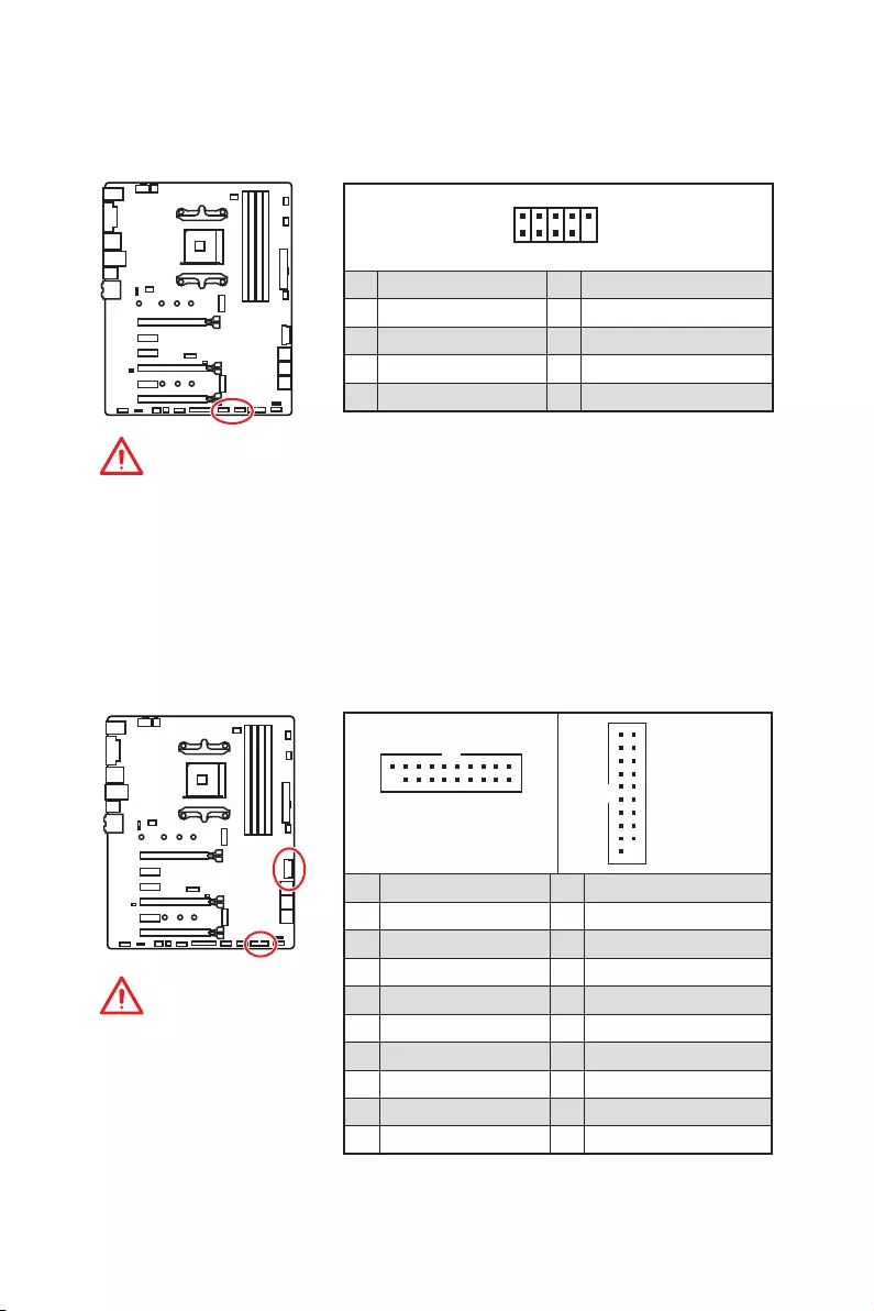
19
Übersicht der Komponenten
JUSB3~4: USB 3.2 Gen1 Anschlüsse
Mit diesen Anschlüssen können Sie die USB 3.2 Gen1 Anschlüsse auf dem Frontpanel
verbinden.
Wichtig
Bitte beachten Sie, dass
Sie die mit „Stromführende
Leitung“ und „Erdleitung“
bezeichneten Pins korrekt
verbinden müssen, ansonsten
kann es zu Schäden kommen.
1 10
1120
JUSB3
1
10 11
20
JUSB4
1Power 11 USB2.0+
2 USB3_RX_DN 12 USB2.0-
3 USB3_RX_DP 13 Ground
4 Ground 14 USB3_TX_C_DP
5 USB3_TX_C_DN 15 USB3_TX_C_DN
6 USB3_TX_C_DP 16 Ground
7 Ground 17 USB3_RX_DP
8 USB2.0- 18 USB3_RX_DN
9 USB2.0+ 19 Power
10 NC 20 No Pin
JUSB1~2: USB 2.0 Anschlüsse
Mit diesen Anschlüssen können Sie die USB 2.0 Anschlüsse auf dem Frontpanel
verbinden.
1
2 10
9
1VCC 2VCC
3 USB0- 4 USB1-
5 USB0+ 6 USB1+
7 Ground 8 Ground
9 No Pin 10 NC
Wichtig
y
Bitte beachten Sie, dass Sie die mit VCC (Stromführende Leitung) und Ground
(Erdleitung) bezeichneten Pins korrekt verbinden müssen, ansonsten kann es zu
Schäden kommen.
y
Um ein iPad, iPhone und einen iPod über USB-Anschlüsse aufzuladen, installieren
Sie bitte die MSI
®
SUPER CHARGER Software.
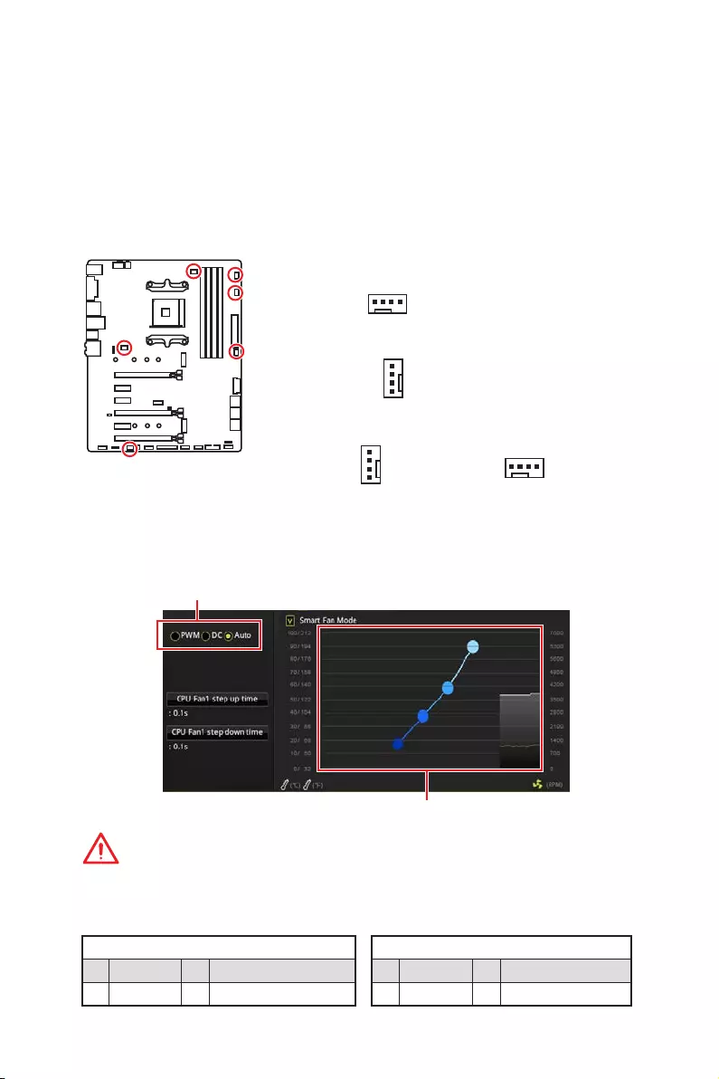
20 Übersicht der Komponenten
CPU_FAN1, PUMP_FAN1, SYS_FAN1~4: Stromanschlüsse für
Lüfter
Diese Anschlüsse können im PWM (Pulse Width Modulation) Modus
oder Spannungsmodus betrieben werden. Im PWM-Modus bieten die
Lüfteranschlüsse konstante 12V Ausgang und regeln die Lüftergeschwindigkeit
per Drehzahlsteuersignal. Im DC-Modus bestimmen die Lüfteranschlüsse die
Lüftergeschwindigkeit durch Ändern der Spannung. Wenn Sie ein 3-Pin (Non-PWM)
Lüfter an einen PWM-Modus Lüfteranschluss anschließen, läuft der Lüfter mit
höchster Drehzahl und kann unangenehm laut werden. Folgen Sie den folgenden
Anweisungen, um den PWM- oder DC-Modus auszuwählen.
Pin-Belegung des PWM-Modus
1 Ground 2 +12V
3 Sense 4 Speed Control Signal
Pin-Belegung des DC-Modus
1 Ground 2 Voltage Control
3 Sense 4 NC
Lüfteranschlüsse des Standard-PWM-Modus
Lüfteranschlüsse des Standard-DC-Modus
Umschalten des Lüfter-Modus und Anpassung der Lüfterdrehzahl
Sie können unter BIOS > HARDWARE MONITOR zwischen dem PWM- und DC-Modus
umschalten und die Lüfterdrehzahl ändern.
Wählen Sie den PWM- oder DC-Modus aus
Wichtig
Überprüfen Sie die ordnungsgemäße Funktion der Lüfter nach dem Umschalten des
PWM-/ DC-Modus.
Die Gradientenpunkte des Lüfterverlaufs erlauben die
Anpasssung der Lüfterdrehzahl in Abhängigkeit von der CPU-
Temperatur.
1
SYS_FAN1/ SYS_FAN3/ SYS_FAN4
1
SYS_FAN2
1
CPU_FAN1
Pin-Belegung der Lüfteranschlüsse
üfteranschlüsse des Standard-Auto-Modus
1
PUMP_FAN1
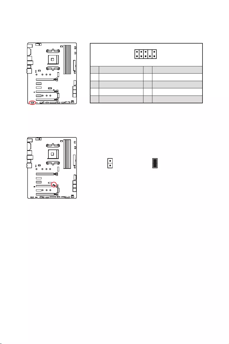
21
Übersicht der Komponenten
JAUD1: Audioanschluss des Frontpanels
Dieser Anschluss ermöglicht den Anschluss von Audiobuchsen eines Frontpanels.
1
2 10
9
1 MIC L 2 Ground
3 MIC R 4 NC
5 Head Phone R 6 MIC Detection
7 SENSE_SEND 8 No Pin
9 Head Phone L 10 Head Phone Detection
JCI1: Gehäusekontaktanschluss
Dieser Anschluss wird mit einem Kontaktschalter verbunden.
Normal
(Standardwert)
Löse den
Gehäuseeingriff aus
Gehäusekontakt-Detektor verwenden
1. Schließen Sie den JCI1-Anschluss am Gehäusekontakt-Schalter/ Sensor am
Gehäuse an.
2. Schließen Sie die Gehäuseabdeckung.
3. Gehen Sie zu BIOS > Settings > Security > Chassis Intrusion Configuration.
4. Stellen Sie Chassis Intrusion auf Enabled.
5. Drücken Sie F10 zum Speichern und Beenden und drücken Sie dann die Enter—
Taste, um Ja auszuwählen.
6. Bei eingeschaltetem Computer wird eine Warnmeldung auf dem Bildschirm
angezeigt, wenn die Gehäuseabdeckung wieder geöffnet wird.
Gehäusekontakt-Warnung zurücksetzen
1. Gehen Sie zu BIOS > Settings > Security > Chassis Intrusion Configuration.
2. Stellen Sie Chassis Intrusion auf Reset.
3. Drücken Sie F10 zum Speichern und Beenden und drücken Sie dann die Enter—
Taste, um Ja auszuwählen.
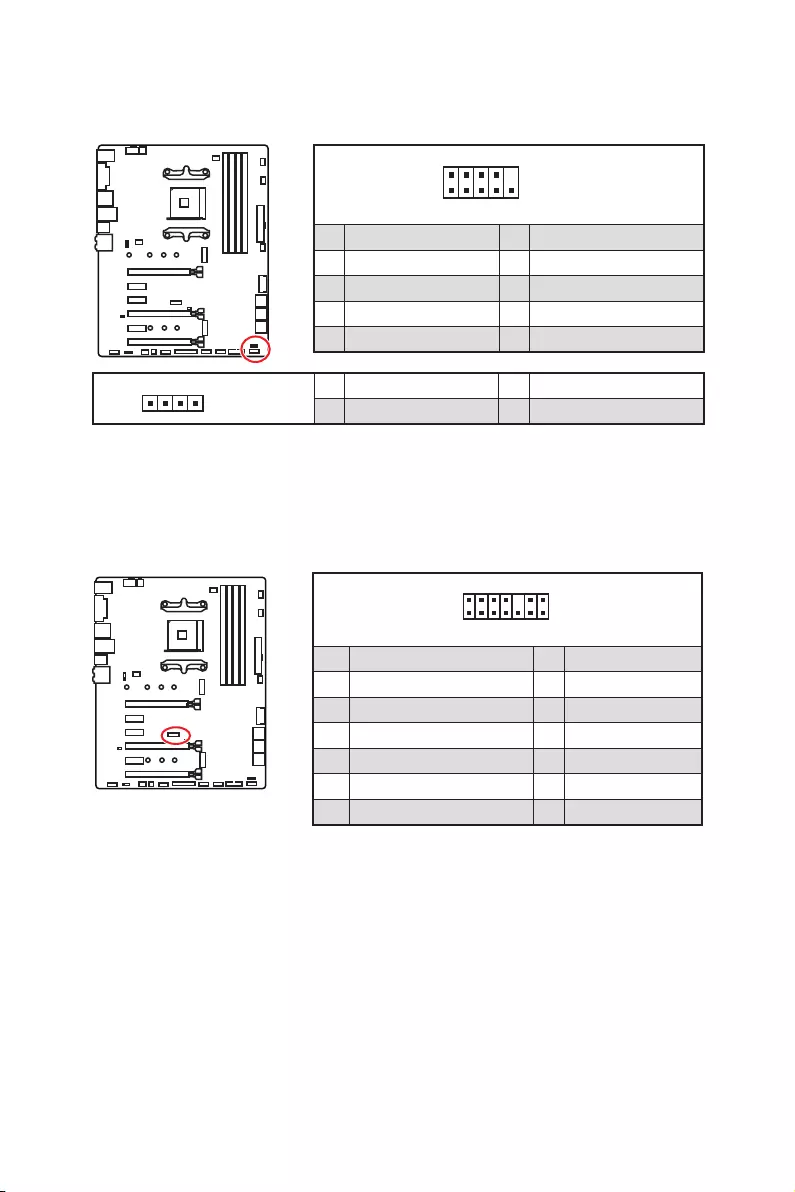
22 Übersicht der Komponenten
1
2 14
13
1 LPC Clock 2 3V Standby power
3 LPC Reset 4 3.3V Power
5 LPC address & data pin0 6 Serial IRQ
7 LPC address & data pin1 8 5V Power
9 LPC address & data pin2 10 No Pin
11 LPC address & data pin3 12 Ground
13 LPC Frame 14 Ground
JTPM1: TPM Anschluss
Dieser Anschluss wird für das TPM Modul (Trusted Platform Module) verwendet.
Weitere Informationen über den Einsatz des optionalen TPM Modules entnehmen Sie
bitte dem TPM Plattform Handbuch.
JFP1, JFP2: Frontpanel-Anschlüsse
Diese Anschlüsse verbinden die Schalter und LEDs des Frontpanels.
1
2 10
9
JFP1
1 HDD LED + 2 Power LED +
3 HDD LED — 4 Power LED —
5 Reset Switch 6 Power Switch
7 Reset Switch 8 Power Switch
9 Reserved 10 No Pin
1
JFP2
1 Speaker — 2 Buzzer +
3 Buzzer — 4 Speaker +
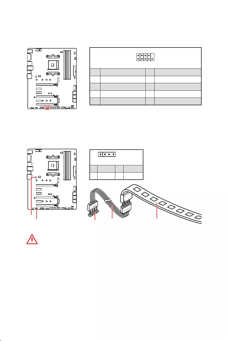
23
Übersicht der Komponenten
JRGB1, JRGB2: RGB LED Anschlüsse
Mit diesem JRGB1/JRGB2-Anschluss können Sie den 5050 RGB-LED-Streifen (12 V)
und AMD CPU Cooler mit RGB LED anschließen.
Wichtig
y
Dieser JRGB1/JRGB2-Anschluss unterstützt die 5050 RGB LED -Streifen (12V/G/R/B)
mit der maximalen Leistung von 3 A (12 V).
y
Beachten Sie bitte, dass die Länge des LED-Streifens maximal 2 Meter betragen darf
um eine Verdunkelung der LED zu verhindern.
y
Schalten Sie die Stromversorgung aus und ziehen Sie das Netzkabel ab, bevor Sie
die RGB-LED-Streifen ein- und ausbauen.
y
Bitte verwenden Sie die MSI-Software zur Steuerung des LED-Leuchtstreifens.
1
JRGB1/
JRGB2
JRGB1
JRGB2 Verlängerungskabel 5050 RGB LED Streifen 12V
1
JRGB1
JRGB2
1 +12V 2 G
3 R 4 B
1
2 10
9
1 DCD 2 SIN
3 SOUT 4 DTR
5 Ground 6 DSR
7 RTS 8 CTS
9 RI 10 No Pin
JCOM1: Serieller Anschluss
Mit diesem Anschluss können Sie das optionale serielle Schnittstelle mit dem
Einbausatze verbinden.
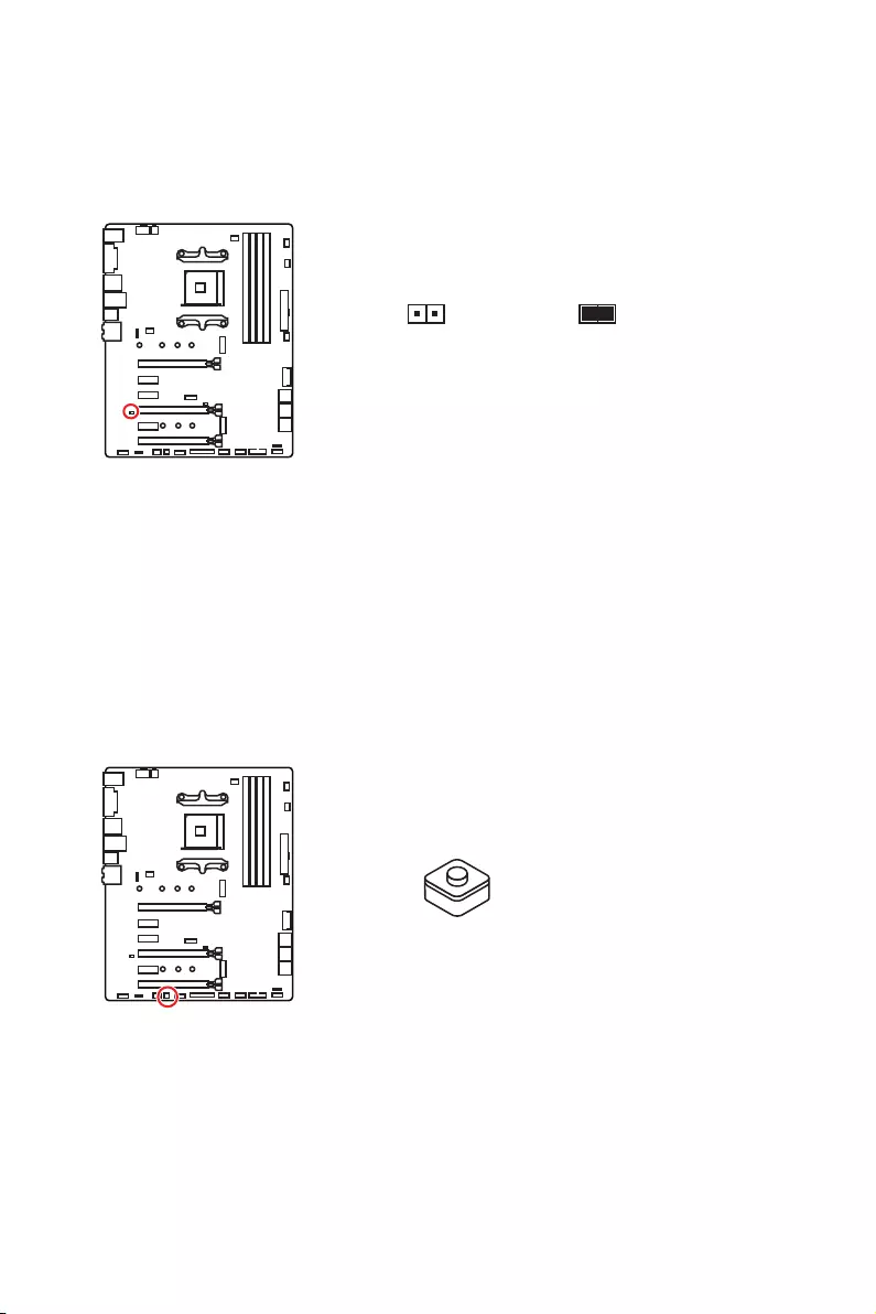
24 Übersicht der Komponenten
JBAT1: Clear CMOS Steckbrücke (Reset BIOS)
Der Onboard CMOS Speicher (RAM) wird durch eine externe Spannungsversorgung
durch eine Batterie auf dem Motherboard versorgt, um die Daten der
Systemkonfiguration zu speichern. Wenn Sie die Systemkonfiguration löschen wollen,
müssen Sie die Steckbrücke für kurze Zeit umsetzen.
Daten
beibehalten
(Standardwert)
CMOS-Daten
löschen/ Reset
des BIOS
Rücksetzen des BIOS auf Standardwerte
1. Schalten Sie den Computer ab und ziehen Sie das Netzkabel ab.
2. Verwenden Sie eine Steckbrücke, um JBAT1 für 5-10 Sekunden kurzzuschließen.
3. Entfernen Sie die Steckbrücke von JBAT1.
4. Stecken Sie das Kabel Ihres Computers in die Steckdose hinein und schalten Sie
den Computer ein.
CLR_CMOS1: Clear CMOS Taste
Schalten Sie den Computer aus. Halten Sie die Taste „Clear CMOS“ für 5-10 Sekunden
gedrückt, um das BIOS auf die Standardwerte zurückzusetzen.
Clear CMOS Taste

25
BIOS Setup
BIOS Setup
Die Standardeinstellungen bieten die optimale Leistung für die Systemstabilität unter
Normalbedingungen. Sie sollten immer die Standardeinstellungen behalten, um
mögliche Schäden des Systems oder Boot-Fehler zu vermeiden, außer Sie besitzen
ausreichende BIOS Kenntnisse.
Wichtig
y
BIOS Funktionen werden für eine bessere Systemleistung kontinuierlich aktualisiert.
Deswegen können die Beschreibungen leicht von der letzten Fassung des BIOS
abweichen und sollten demnach nur als Anhaltspunkte dienen. Für eine Beschreibung
der BIOS Funktionen rufen Sie die HELP Informationstafel aus.
y
Die Bilder in diesem Kapitel stellen lediglich Referenzen dar und können von dem
von Ihnen erworbenen Produkt abweichen.
Öffnen des BIOS Setups
Während des BOOT-Vorgangs drücken Sie die Taste ENTF, wenn die Meldung Press
DEL key to enter Setup Menu, F11 to enter Boot Menu erscheint.
Funktionstasten
F1: Allgemeine Hilfe
F2: Hinzufügen/Entfernen eines Favoritenpunkts
F3: Öffnen des Favoriten Menüs
F4: Öffnen des Menüs CPU-Spezifikationen
F5: Öffnen des Memory-Z Menüs
F6: Laden der ursprünglichen Setup-Standardwerte
F7: Wechselt zwischen dem Erweiterten-Modus und EZ-Modus
F8: OC-Profil wird vom USB-Stick geladen
F9: OC-Profil wird auf einem USB-Stick gespeichert
F10: Speichern oder Zurücksetzen der Änderungen*
F12: Macht einen Screenshot und speichert auf einen FAT/FAT32-USB-Laufwerk.
Strg+F: Öffnet die Suchseite
* Beim Drücken der F10 Taste wird das Fenster zum Speichern der Einstellungen
angezeigt. Wählen Sie Yes, um die Wahl zu bestätigen, oder No, um die derzeitige
Einstellung beizubehalten.

26 BIOS Setup
Reset des BIOS
Sie können die Werkseinstellung wieder herstellen, um bestimmte Probleme zu lösen.
Es gibt verschiedene Möglichkeiten, um das BIOS zurückzusetzen:
yÖffnen Sie das BIOS und drücken Sie F6, um optimierten Einstellungen zu laden.
ySchließen Sie die Clear CMOS Taste an das Motherboard an.
Wichtig
Bitte lesen Sie für Informationen zum BIOS-Reset im Bereich „Clear CMOS Taste“
nach.
Aktualisierung des BIOS
Aktualisierung des BIOS mit dem M-FLASH-Programm
Vorbereitung:
Laden Sie bitte die neueste BIOS Version, die dem Motherboard-Modell entspricht, von
der offiziellen MSI Website herunter und speichern Sie die BIOS-Datei auf USB-Flash-
Laufwerk.
BIOS-Aktualisierungsschritte:
1. Schließen das USB-Flashlaufwerk mit der BIOS-Datei an den Computer.
2. Drücken Sie während des POST-Vorgangs die Taste <Ctrl+F5>.
3. Klicken Sie auf Yes (Ja), um das System neu zu starten. Rufen Sie den Flash-
Modus auf.
4. Wählen Sie die BIOS-Datei zur Durchführung des BIOS-Aktualisierungsprozesses
aus.
5. Nachdem das Flashen des BIOS vollständig ist, startet das System automatisch
neu.
Aktualisierung des BIOS mit Live Update 6
Vorbereitung:
Stellen Sie sicher, dass zuvor die LAN-Treiber installiert wurden und eine
Internetverbindung eingerichtet ist.
BIOS-Aktualisierungsschritte:
1. Installieren und starten Sie „MSI LIVE UPDATE 6“.
2. Wählen Sie BIOS Update aus.
3. Klicken Sie auf die Scan Taste.
4. Klicken Sie auf dieses Download-Icon, um die neueste BIOS-Datei zu laden und zu
installieren.
5. Klicken Sie auf Next (Weiter) und wählen Sie In Windows Mode aus. Und klicken
dann auf Next (Weiter) und Start (Starten), um das BIOS-Update zu starten.
6. Nachdem das Flashen des BIOS vollständig ist, startet das System automatisch
neu.
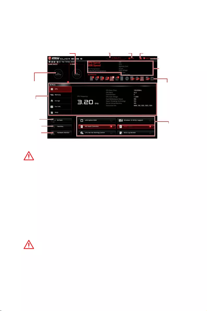
27
BIOS Setup
EZ Modus
Im EZ-Modus können Sie die Grundinformationen des Systems einsehen und
grundlegende Einstellungen konfigurieren. Um sich die erweiterten BIOS-
Einstellungen anzeigen zu lassen, aktivieren Sie bitte den Erweiterten Modus durch
Drücken des Setup Modus Schalter oder der Funktionstaste F7.
Informations-
anzeige
System-
information
Bootgeräte-
Prioritätsleiste
Funktions-
tasten
Sprache
Suchen
Screenshot
Setup Modus Schalter
M-Flash
Favoriten
Hardware
Monitor
GAME BOOST
Schalter
A-XMP Schalter
yGAME BOOST Schalter — Klicken Sie den Schalter, um GAME BOOST für OC zu
wechseln.
Wichtig
Bitte ändern Sie keine Werte im OC Menü und laden Sie keine Standardwerte während
GAME BOOST aktiviert ist, um die optimale Leistung und Stabilität des Systems zu
gewährleisten.
yA-XMP Schalter (optional) — Klicken Sie auf den inneren Kreis, um den A-XMP.
Schalter zu aktivieren/deaktivieren. Drehen Sie den äußeren Kreis, um ein
Speicherprofil zu wählen. Dieser Schalter steht nur zur Verfügung, wenn die
installierten Speichermodule diese Funktion unterstützen.
ySetup Modus Schalter -Mit dieser Registerkarte oder der F7-Taste können Sie
zwischen dem Erweiterten-Modus und EZ-Modus wechseln.
yScreenshot — Wählen Sie diese Registerkarte oder betätigen Sie die F12-Taste, um
einen Screenshot zu machen und auf einen FAT/FAT32-USB-Laufwerk zu speichern.
ySuchen — Klicken Sie auf diese Registerkarte oder die Strg+F Taste um die Suchseite
anzuzeigen. Mit der Funktion können Sie durch Eingabe eines Suchbegriffs nach BIOS-
Einträgen suchen. Bewegen Sie den Mauszeiger über einen freien Bereich und klicken
Sie mit der rechten Maustaste, um die Suchseite zu schließen.
Wichtig
Auf der Suchseite stehen nur die F6-, F10- und F12-Funktionstasten zur Verfügung.
ySprache — Hier können Sie die Sprache der BIOS-Einstellungen auswählen.
ySysteminformationen — Diese zeigt CPU/ DDR-Frequenz, CPU/ MB-Temperatur, MB/
CPU-Typ, Speicherkapazität, CPU/ DDR-Spannung, BIOS-Version und Erstellungs-
Datum.

28 BIOS Setup
yBoot-Geräte Prioritätsleiste — Sie können die Gerätesymbole verschieben, um die
Startreihenfolge zu ändern. Die Bootreihenfolge sind mit “hoch”(links) bis “niedrig”
(rechts) bezeichnet.
yInformationsanzeige — Klicken Sie auf die Schaltfläche CPU, Memory, Storage, Fan
Info und Help auf der linken Seite, um die jeweiligen Informationen anzuzeigen.
yFunktionstasten — Aktivieren oder deaktivieren Sie LAN Option ROM, HD Audio
Controller, Window 10 WHQL Support, AHCI, RAID, CPU Fan Fail Warning Control und
BIOS Log Review durch Anklicken der zugehörigen Schaltfläche.
Wichtig
y
Während des Windows Setup-Vorgangs benötigen Sie den RAID-Treiber, den Sie auf
der MSI-Treiber-CD finden.
y
Sie können das MSI SMART TOOL verwenden, um das Windows
®
7/ 8.1/ 10-
Installationslaufwerk mit dem RAID-Treiber zu erstellen.
y
Wenn ihr M.2 SSD RAID-Volumen als Windows-Startvolumen eingestellt ist und Sie
das RAID-Volumen im UEFI BIOS löschen, ist Ihr System nicht mehr bootfähig.
yM-Flash — Ein Klick auf diese Schaltfläche öffnet M-Flash mit dem Sie das BIOS mit
einem USB-Flash-Laufwerk aktualisieren.
yHardware Monitor — Ein Klick auf diese Schaltfläche öffnet das Menü des Hardware
Monitor mit dem Sie die Lüfterdrehzahl in Prozent manuell steuern.
yFavoriten — Drücken Sie die F3-Taste, um das Favoriten-Menü aufzurufen. Hier
können Sie Ihre persönliches BIOS-Menü erstellen, in dem Sie die häufig verwendeten
oder favorisierten BIOS-Einstellungsoptionen auswählen können.
Default HomePage — Über diese Option können Sie ein BIOS-Menü (zum Beispiel:
Einstellungen, Übertaktung, usw.) als BIOS Homepage auswählen.
Favoriten 1~5 — Hier können Sie die häufig erwendeten oder favorisierten BIOS-
Einstellungsoptionen auf einer Seite hinzufügen.
Um ein BIOS-Punkte zu einer Favoritenseite hinzufügen (Lieblingseinstellung
1~5)
1. Sie können die Maus nicht nur über einen Eintrag im BIOS-Menü sondern
auch auf der Suchseite bewegen.
2. Klicken Sie mit der rechten Maustaste oder drücken Sie die Taste F2.
3. Wählen Sie die gewünschte Seite aus und klicken Sie auf OK.
Um ein BIOS-Punkte von Favoritenseite zu löschen
1. Bewegen Sie die Maus über einen BIOS-Eintrag auf einer Favoritenseite
(Favoriten 1~5)
2. Klicken Sie mit der rechten Maustaste oder drücken Sie die Taste F2.
3. Wählen Sie Delete aus und klicken Sie auf OK.
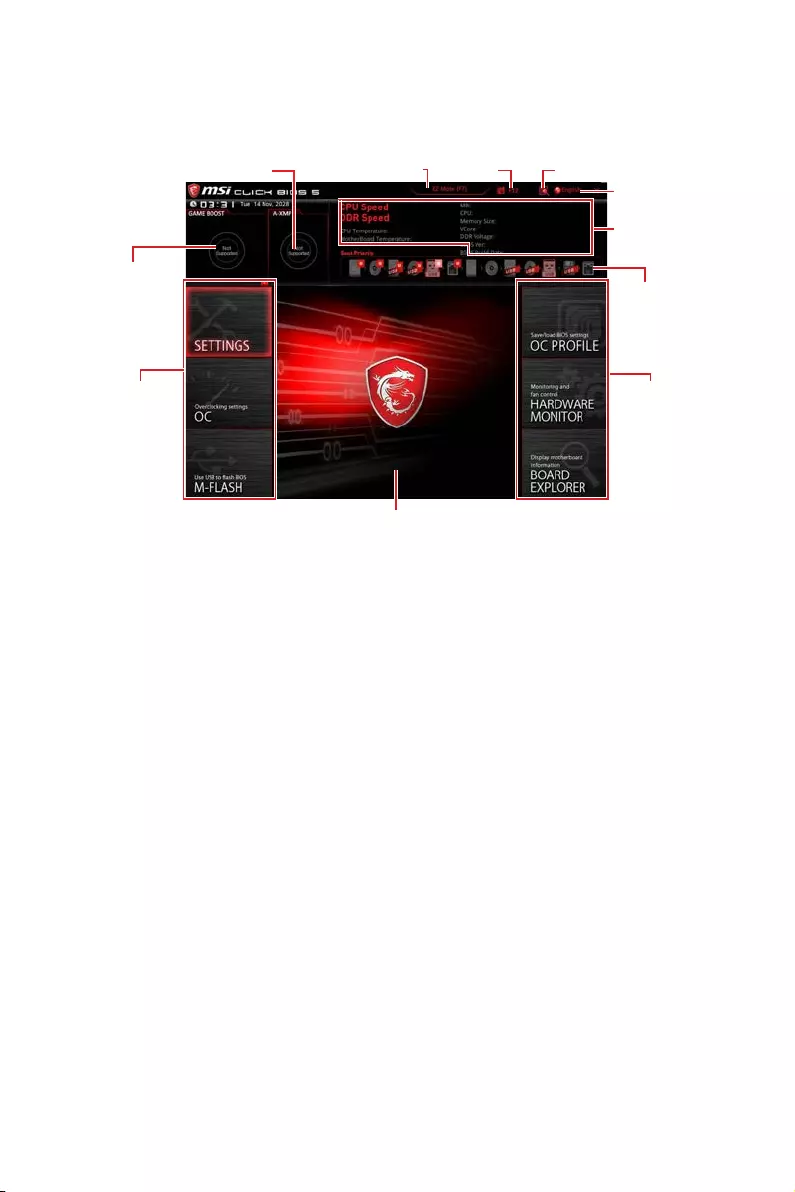
29
BIOS Setup
Erweiterter Modus
Drücken Sie den Setup Modus Schalter oder die Funkionstaste F7, um zwischen dem
EZ-Modus und Erweiterten-Modus im BIOS-Setup zu wechseln.
A-XMP Schalter
GAME BOOST
Schalter
System-
information
Bootgeräte-
Prioritätsleiste
BIOS-Menü
-Auswahl
Sprache
Suchen
Screenshot
Setup Modus Schalter
Menüanzeige
BIOS-Menü
-Auswahl
yGAME BOOST Schalter/ Setup Modus Schalter/ Screenshot/ Sprache/
Systeminformation/ Boot-Geräte Prioritätsleiste — Finden Sie die Informationen in
den Beschreibungen der EZ Modus-Abschritt.
yBIOS-Menü-Auswahl — Die folgenden Optionen stehen zur Verfügung.
SETTINGS — Mit diesem Menü können Sie die Parameter für Chipsatz, Boot-
Geräte angeben.
OC — Hier können Sie die Frequenz und Spannung anpassen. Die Erhöhung der
Frequenz kann eine bessere Leistung erreichen.
M-FLASH — M-Flash erlaubt es, das BIOS mit einem USB-Flash-Laufwerk zu
aktualisieren.
OC PROFILE — In diesem Menü werden die verschiedenen Overclocking-Profile
gespeichert.
HARDWARE MONITOR — Hier können Sie die Geschwindigkeiten der Lüfter
anpassen und die Spannungen des Systems überwachen.
BOARD EXPLORER — Zeigt Ihnen Informationen über Geräte an, die an das
Mainboard angeschlossen sind.
yMenüanzeige — Dieser Bereich ermöglicht die Konfiguration von BIOS Einstellungen.
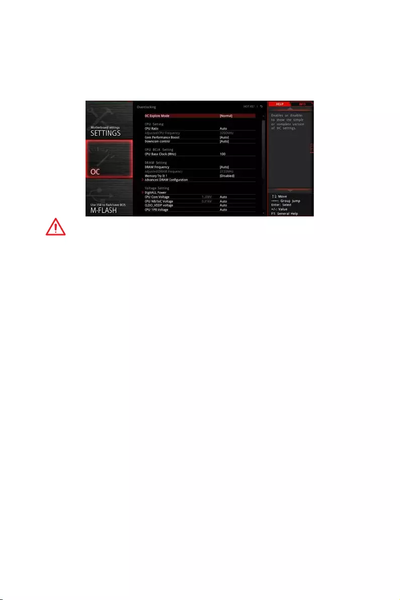
30 BIOS Setup
OC Menü
In diesem Menü können Benutzer das BIOS anpassen und das Mainboard übertakten.
Bitte führen Sie nur Änderungen durch, wenn Sie sich über das Ergebnis im Klaren
sind. Sie sollten Erfahrung beim Übertakten haben, da Sie sonst das Motherboard
oder Komponenten des Systems beschädigen können.
Wichtig
y
Die Übertaktung ist nur für fortgeschrittene Benutzer zu empfehlen.
y
Eine erfolgreiche Übertaktung ist nicht gewährleistet. Die Anwendung von
Übertaktungsmaßnahmen kann zu Verlust der Garantie oder zur Beschädigung der
Hardware führen.
y
Falls Sie sich mit der Übertaktung nicht auskennen, empfehlen wir für einfaches
Übertakten die GAME BOOST Funktion.
y
Die BIOS-Funktionen im OC Menü werden abhängig von dem Prozessor variieren.
fOC Explore Mode [Normal]
Aktivieren oder deaktivieren Sie die Funktion, um die normale oder Expertenversion
des OC-Einstellungen anzuzeigen.
[Normal] Bietet normale Übertaktungseinstellungen im BIOS-Setup.
[Expert] Bietet die erweiterten Übertaktungseinstellungen für den erfahrenen
Benutzer, welche die Einstellungen im BIOS-Setup konfigurieren
wollen.
Hinweis: Wir verwenden * als Symbol für die Übertaktungseinstellungen des
Erweiterten Modus.
fCPU Ratio [Auto]
Legen Sie den CPU-Multiplikator fest, um die CPU-Taktfrequenzen zu bestimmen.
Diese Option kann nur geändert werden, wenn der Prozessor diese Funktion
unterstützt.
fCore Performance Boost [Auto]
Aktiviert oder Deaktiviert die Core Performance Boost (CPB). Diese Option erscheint
nur, wenn die CPU die Funktion unterstützt.
fDowncore Control [Auto] (optional)
Legt die Anzahl der verwendeten CPU-Kerne fest. Diese Option erscheint nur, wenn
die CPU die Funktion unterstützt.

31
BIOS Setup
fA-XMP [Disabled]
Aktivieren Sie die A-XMP Funktion oder wählen Sie ein Profil des Speichermoduls aus,
um den Speicher zu übertakten. Diese Option erscheint nur, wenn die installierten
Speichermodule/ das installierte Motherboard diese Funktion unterstützen.
fDRAM Frequency [Auto]
Setzen Sie die DRAM Frequenz. Bitte beachten Sie, dass ein zuverlässiges
Übertaktungsverhalten nicht garantiert werden kann.
fMemory Try It ! [Disabled]
Die Option „Memory Try It!“ dient der Verbesserung der Speicherkompatibilität
oder auch der Speicherleistung durch die Auswahl der optimierten Speicher-
Voreinstellungen.
fMemory Retry Count [5]
Konfiguriert die Anzahl der Wiederholungen mit dem gesetzten Speicherprofil. Wenn
die Übertaktung des Speichers erfolglos ist, wird diese Einstellung auf [5] gesetzt.
Damit kann das System 5 mal mit der gleichen übertakteten Konfiguration neu
starten. Wenn die Übertaktung jedesmal fehlgeschlagen ist, setzt das System die
Einstellungen auf die Werkseinstellung zurück.
fAdvanced DRAM Configuration (optional)
Drücken Sie die Eingabetaste <Enter>, um das Untermenü aufzurufen. Der Anwender
kann die Speicher-Timing für jeden Kanal des Speichers einstellen. Das System
könnte nach dem Ändern der Speicher-Timings instabil werden oder nicht mehr
booten. Wenn Instabilität auftritt, löschen Sie bitte die CMOS-Daten und stellen
Sie die Standardeinstellungen wieder her. (Lesen Sie bitte den Abschnitt „Clear
CMOS Steckbrücke/ Taste (optional)“, um die CMOS-Daten zu löschen, und die
Standardeinstellungen auf das BIOS zu laden.)
fDigitALL Power
Drücken Sie die Eingabetaste <Enter>, um das Untermenü aufzurufen. Steuert die
digitale CPU PWM.
fCPU Loadline Calibration Control [Auto]
Die CPU-Spannung verringert proportional zur CPU-Belastung. Höheres Loadline-
Calibration könnten eine höhere Spannung und einen höheren Übertaktungswert
bekommen, auch einen Temperaturanstieg der CPU und VRM verursachen.Wenn
die Einstellung auf Auto gesetzt ist, wird das BIOS diese Einstellungen automatisch
konfigurieren.
fCPU Over Voltage Protection [Auto]
Legen Sie die Spannungsgrenze für den CPU-Überspannungsschutz fest. Wenn die
Einstellung auf Auto gesetzt ist, wird das BIOS diese Einstellungen automatisch
konfigurieren. Höhere Spannung bietet weniger Sicherheit und kann das System
beschädigen.
fCPU Under Voltage Protection [Auto]
Legen Sie die Spannungsgrenze für den CPU-Unterspannungsschutz fest. Wenn
die Einstellung auf Auto gesetzt ist, wird das BIOS diese Einstellungen automatisch
konfigurieren. Höhere Spannung bietet weniger Schutz und kann das System
beschädigen.

32 BIOS Setup
fCPU Over Current Protection [Auto]
Legen Sie den aktuellen Grenzwert für den CPU-Überstromschutz fest. Wenn die
Einstellung auf Auto gesetzt ist, wird das BIOS diese Einstellungen automatisch
konfigurieren.
[Auto] Diese Einstellungen werden vom BIOS automatisch konfiguriert.
[Enhanced] Erweitert die Begrenzung des Speicher-Überstromschutz.
fCPU Switching Frequency [Auto]
Stellen Sie die PWM Arbeitsgeschwindigkeit ein, um die CPU Core-Spannung und
den Ripple Bereich zu stabilisieren. Die Erhöhung der PWM Arbeitsgeschwindigkeit
verursachen höhere Temperatur der MOSFET. So stellen Sie bitte sicher, dass Sie
eine ausreichende Kühlung für MOSFET besitzen, bevor Sie den Wert erhöhen.
Wenn die Einstellung auf Auto gesetzt ist, wird das BIOS diese Einstellungen
automatisch konfigurieren.
fCPU VRM Over Temperature Protection [Auto]
Setzen Sie für den Übertemperaturschutz die Temperaturgrenze auf CPU
VRM. Die CPU-Frequenz kann gedrosselt werden, wenn CPU VRM über die
Temperaturgrenze erhöht. Wenn die Einstellung auf Auto gesetzt ist, wird das BIOS
diese Einstellungen konfigurieren.
fCPU Power Duty Control [Thermal Balance]
Legen Sie den Strom der jeden VRM Phase und die thermischen Bedingungen von
jeder Phase-Komponente fest.
[Thermal Balance] wahrt thermisches Gleichgewicht der VRM-Phase.
[Current Balance] wahrt die Strom-Gleichgewicht der VRM-Phase.
fCPU NB Loadline Calibration Control [Auto]
Die CPU-NB-Spannung verringert proportional zur CPU-NB-Belastung. Höheres
Loadline-Calibration könnten eine höhere Spannung und einen höheren
Übertaktungswert bekommen, auch einen Temperaturanstieg verursachen. Wenn
die Einstellung auf Auto gesetzt ist, wird das BIOS diese Einstellungen automatisch
konfigurieren.
fCPU NB Over Current Protection [Auto]
Legen Sie die Spannungsgrenze für den CPU-NB-Überspannungsschutz fest. Wenn
die Einstellung auf Auto gesetzt ist, wird das BIOS diese Einstellungen automatisch
konfigurieren.
[Auto] Diese Einstellungen werden vom BIOS automatisch konfiguriert.
[Enhanced] Erweitert die Begrenzung des Speicher-Überstromschutz.
fCPU NB Switching Frequency [Auto]
Stellen Sie die PWM Arbeitsgeschwindigkeit ein, um die CPU-NB-Spannung und
den Ripple Bereich zu stabilisieren. Die Erhöhung der PWM Arbeitsgeschwindigkeit
verursachen höhere Temperatur der MOSFET. So stellen Sie bitte sicher, dass Sie
eine ausreichende Kühlung für MOSFET besitzen, bevor Sie den Wert erhöhen.
Wenn die Einstellung auf Auto gesetzt ist, wird das BIOS diese Einstellungen
automatisch konfigurieren.
fCPU NB Power Duty Control [Thermal Balance]
Legen Sie den Strom der jeden CPU-NB-VRM Phase und die thermischen
Bedingungen von jeder Phase-Komponente fest.
[Thermal Balance] wahrt thermisches Gleichgewicht der VRM-Phase.
[Current Balance] wahrt die Strom-Gleichgewicht der VRM-Phase.

33
BIOS Setup
fVR 12VIN OCP Expander [Auto]
Erweitert die Begrenzung des VR-Überstromschutzes mit 12 V Eingangsspannung.
Dies kann aufgrund erhöhter Toleranz einen geringeren Schutz bedeuten. Bitte
passen Sie deshalb den Strom sorgfältig an, um Beschädigungen des CPU/ VR
MOS zu vermeiden. Wenn die Einstellung auf [Auto] gesetzt ist, wird das BIOS diese
Einstellungen automatisch konfigurieren.
fCPU Voltages control [Auto]
Erlaubt das Einstellen der CPU-Spannungen. Wenn die Einstellung auf Auto gesetzt
ist, wird das BIOS die Spannungen automatisch einstellen oder Sie können es manuell
einstellen.
fDRAM Voltages control [Auto]
Erlaubt das Einstellen der DRAM-Spannungen. Wenn die Einstellung auf Auto gesetzt
ist, wird das BIOS die Spannungen automatisch einstellen oder Sie können es manuell
einstellen.
fMemory Changed Detect [Enabled]*
Aktiviert/Deaktiviert die Systemwarnmeldung beim Booten, wenn die CPU oder der
Hauptspeicher ersetzt wurde.
[Enabled] Das System zeigt eine Warnmeldung beim Systemstart und lädt die
Default-Einstellungen für neue Geräte.
[Disabled] Deaktivierung der Funktion und Beibehaltung der aktuellen BIOS-
Einstellungen.
fCPU Specifications
Drücken Sie die Eingabetaste <Enter>, um das Untermenü aufzurufen. Das
Untermenü zeigt die Informationen der installierten CPU an. Zu diesen Informationen
gelangen Sie, indem Sie die Taste [F4] drücken. Nur Anzeige.
fCPU Technology Support
Drücken Sie die Eingabetaste <Enter>, um das Untermenü aufzurufen. Das
Untermenü zeigt die wichtigsten Eigenschaften der installierten CPU an.
fMEMORY-Z
Drücken Sie die Eingabetaste <Enter>, um das Untermenü aufzurufen. Dieses
Untermenü zeigt alle Einstellungen und Timings des installierten Speichers. Zu diesen
Informationen gelangen Sie auch, indem Sie die Taste [F5] drücken.
fDIMMx Memory SPD
Drücken Sie die Eingabetaste <Enter>, um das Untermenü aufzurufen. Das
Untermenü zeigt die Informationen des verwendeten Speichers an. Nur Anzeige.
fCPU Features
Drücken Sie die Eingabetaste <Enter>, um das Untermenü aufzurufen.
fSimultaneous Multi-Threading [Enabled] (optional)
Aktiviert oder deaktiviert das AMD Simultaneous Multi-Threading. Diese Option
erscheint nur, wenn die installierte CPU die Technologie unterstützt.
fGlobal C-state Control [Enabled] (optional)
Aktiviert oder deaktiviert die IO-basierten C-States und DF C-States.

34 BIOS Setup
fOpcache Control [Auto] (optional)
Aktiviert oder deaktiviert die Opcache-Funkiton. Opcache speichert die letzte
dekodierte Anweisung um die Dekodierzeit bei wiederholten Anweisungen zu
verringern. Zusätzlich kann es die CPU-Leistung erhöhen und den Stromverbrauch
leicht reduzieren.
fIOMMU Mode (optional)
Hier können Sie den IOMMU (I/O Memory Management Unit) für I/O-Virtualisierung
aktivieren/ deaktivieren.
fSpread Spectrum (optional)
Diese Funktion reduziert die EMI (Electromagnetic Interference) durch Modulation
Taktgenerator erzeugten Impulse.
[Enabled] Aktiviert die Spread-Spectrum-Funktion, um die elektromagnetische
Wechselwirkung zu verringern.
[Disabled] Steigert die Übertaktungs-Fähigkeiten des CPU-Grundtakts.
Wichtig
y
Sollten Sie keine Probleme mit Interferenzen haben, belassen Sie es bei der
Einstellung [Disabled] (ausgeschaltet) , um bestmögliche Systemstabilität und
-leistung zu gewährleisten. Stellt für sie EMI ein Problem dar, wählen Sie die
gewünschte Bandbreite zur Reduktion der EMI.
y
Je größer Spread Spectrum Wert ist, desto größer nimmt der EMI ab, und das
System wird weniger stabil. Bitte befragen Sie Ihren lokalen EMI Regelung zum meist
passend Spread Spectrum Wert.
y
Denken Sie daran Spread Spectrum zu deaktivieren, wenn Sie übertakten, da sogar
eine leichte Schwankung eine vorübergehende Taktsteigerung erzeugen kann, die
gerade ausreichen mag, um Ihren übertakteten Prozessor zum einfrieren zu bringen.
fRelaxed EDC throttling [Auto] (optional)
Relaxed EDC throttling reduziert die Zeit, in der der Prozessor gedrosselt wird. the
cores.
[Auto] Empfehlung von AMD
[Enabled] Reduziert die Zeit, in der der Prozessor gedrosselt wird.
[Disabled] Der spezifische EDC-Drosselschutz ist aktiviert.
fAMD Cool’n’Quiet [Enabled]
Die Cool’n’Quiet-Technologie kann die CPU-Geschwindigkeit und den
Stromverbrauch effizient und dynamisch herabsetzen.
fSVM Mode [Disabled]
Aktiviert oder deaktiviert den AMD SVM (Secure Virtual Machine) Modus.
fBIOS PSP Support [Enabled] (optional)
Aktiviert oder deaktiviert die Funktion BIOS PSP Support. Es steuert den PSP-
Unterpunkt einschließlich C2P/ P2C-Mailbox, Secure-S3 und fTPM-Support.
fPower Supply Idle Control [Auto] (optional)
Erlaubt den Energiespar-Modus für die CPU wenn sich alle Kerne im Zustand
non-CO befinden. Wenn die Einstellung auf Auto gesetzt ist, wird das BIOS diese
Einstellungen automatisch konfigurieren.

35
Softwarebeschreibung
Softwarebeschreibung
Installation von Windows® 10
1. Schalten Sie den Computer ein.
2. Legen Sie die Windows® 10 Disk in das optisches Laufwerk.
3. Drücken Sie die Taste Restart auf dem Computergehäuse.
4. Drücken Sie die F11-Taste während des POST-Vorgangs (Power-On Self Test), um
das Bootmenu zu öffnen.
5. Wählen Sie das optische Laufwerk aus dem Bootmenu.
6. Wenn eine entsprechende Meldung Press any key to boot from CD or DVD…
angezeigt wird, drücken Sie eine beliebige Taste.
7. Folgen Sie den Anweisungen auf dem Bildschirm, um das Dienstprogramm
„Windows® 10“ zu installieren.
Installation von Treibern
1. Starten Sie Ihren Computer mit Windows® 10.
2. Legen Sie die MSI® Treiber Disk in das optisches Laufwerk.
3. Der Installer wird automatisch erscheint und findet und finden Sie die benötigten
Treiber in die Liste.
4. Klicken Sie auf Install.
5. Die Software-Installation ist im Gange. Wenn die Installation abgeschlossen ist,
werden Sie dazu aufgefordet, den Computer neu zu starten.
6. Klicken Sie auf OK zum Beenden.
7. Starten Sie Ihren Computer neu.
Installation von Utilities
Bevor Sie Anwendungen installieren, müssen Sie die Treiber-Installation vollständig
beendet haben.
1. Legen Sie die MSI® Treiber Disk in das optisches Laufwerk.
2. Der Installer wird automatisch erscheint.
3. Klicken Sie auf Utilities.
4. Wählen Sie die Dienstprogramme, die installiert werden soll.
5. Klicken Sie die Taste Install.
6. Die Utilities-Installation ist im Gange. Wenn die Installation abgeschlossen ist,
werden Sie dazu aufgefordet, den Computer neu zu starten.
7. Klicken Sie auf OK zum Beenden.
8. Starten Sie Ihren Computer neu.

36 Softwarebeschreibung
Anmerkung

1
Table des matières
Table des matières
Informations de sécurité …………………………………………………………………………… 2
Spécifications …………………………………………………………………………………………… 3
Panneau arrière Entrée / Sortie ………………………………………………………………… 9
Tableau explicatif de l’état de la LED du port LAN ……………………………………….. 9
Configuration des ports audio …………………………………………………………………….. 9
Realtek HD Audio Manager ………………………………………………………………………. 10
Vue d’ensemble des composants …………………………………………………………….. 12
Socket processeur …………………………………………………………………………………… 13
Slots DIMM ……………………………………………………………………………………………… 14
PCI_E1~6 : Slots d’extension PCIe ……………………………………………………………. 15
M2_1~2 : Slots M.2 (Touche M) ………………………………………………………………….. 17
SATA1~6 : Connecteurs SATA 6 Gb/s …………………………………………………………. 18
JLPT1 : Connecteur de port parallèle ………………………………………………………… 18
CPU_PWR1, CPU_PWR2, ATX_PWR1 : Connecteurs d’alimentation …………….. 19
JUSB1~2 : Connecteurs USB 2.0 ……………………………………………………………….. 20
JUSB3~4 : Connecteurs USB 3.2 Gen1 ………………………………………………………. 20
CPU_FAN1, PUMP_FAN1, SYS_FAN1~4 : Connecteurs pour ventilateurs ………. 21
JAUD1 : Connecteur audio avant ……………………………………………………………….. 22
JCI1 : Connecteur intrusion châssis ………………………………………………………….. 22
JFP1, JFP2 : Connecteurs de panneau avant ……………………………………………… 23
JTPM1 : Connecteur de module TPM …………………………………………………………. 23
JCOM1 : Connecteur de port série …………………………………………………………….. 24
JRGB1, JRGB2 : Connecteurs LED RGB …………………………………………………….. 24
JBAT1 : Cavalier Clear CMOS (Réinitialisation BIOS) …………………………………… 25
CLR_CMOS1 : Bouton Clear CMOS ……………………………………………………………. 25
Configuration du BIOS …………………………………………………………………………….. 26
Entrer dans l’interface Setup du BIOS ………………………………………………………. 26
Réinitialiser le BIOS …………………………………………………………………………………. 27
Mettre le BIOS à jour ……………………………………………………………………………….. 27
EZ Mode (mode simplifié) …………………………………………………………………………. 28
Advanced Mode (mode avancé) ………………………………………………………………… 30
OC Menu (menu overclocking)…………………………………………………………………… 31
Informations sur les logiciels ………………………………………………………………….. 36
Installer Windows® 10 ……………………………………………………………………………… 36
Installer les pilotes ………………………………………………………………………………….. 36
Installer les utilitaires ……………………………………………………………………………… 36

2Informations de sécurité
Informations de sécurité
yLes composants dans l’emballage peuvent être endommagés par des décharges
électrostatiques (ESD). Pour vous assurer de correctement monter votre ordinateur,
veuillez vous référer aux instructions ci-dessous.
yAssurez-vous de bien connecter tous les composants. En cas de mauvaise
connexion, il se peut que l’ordinateur ne reconnaisse pas le composant et que le
démarrage échoue.
yVeuillez tenir la carte mère par les bords pour éviter de toucher les composants
sensibles.
yIl est recommandé de porter un bracelet antistatique lors de la manipulation de la
carte mère pour prévenir tout dommage. Si vous n’avez pas de bracelet antistatique,
touchez un objet métallique relié à la terre avant de manipuler la carte mère afin de
vous décharger de votre charge statique. Touchez régulièrement l’objet métallique
pendant toute la manipulation.
yTant que la carte mère n’est pas installée, conservez-la dans un récipient protégé
contre les ondes électrostatiques ou sur une couche antistatique.
yAvant de démarrer l’ordinateur, vérifiez si toutes les vis et les composants
métalliques sont bien fixés sur la carte mère ou ailleurs dans le boîtier de
l’ordinateur.
yNe démarrez pas l’ordinateur avant d’avoir terminé l’installation. Ceci peut
endommager les composants ou vous blesser.
ySi vous avez besoin d’aide pendant l’installation, veuillez consulter un technicien
informatique certifié.
yAvant d’installer les composants d’ordinateur, veuillez toujours mettre hors tension
et débrancher le cordon d’alimentation.
yGardez ce manuel pour références futures.
yProtégez ce manuel contre l’humidité.
yAvant de brancher le bloc d’alimentation sur la sortie électrique, veuillez
vous assurer que la tension de la sortie électrique est bien égale à celle du bloc
d’alimentation.
yPlacez le cordon d’alimentation de façon à éviter que l’on marche dessus. Ne posez
rien sur le cordon d’alimentation.
yVeuillez prêter attention à toutes les alertes et remarques indiquées sur la carte
mère.
yDans un cas comme ci-dessous, faites appel au service autorisé pour vérifier votre
carte mère :
Un liquide a pénétré dans l’ordinateur.
La carte mère a été exposée à de l’humidité.
La carte mère ne fonctionne pas comme indiqué dans les instructions.
La carte mère est tombée par terre et a été endommagée.
La carte mère est cassée.
yNe pas mettre la carte mère dans un environnement dont la température est
supérieure à 60°C (140°F) sous peine de l’endommager.

3
Spécifications
Spécifications
CPU
Socket AM4 pour processeurs AMD Ryzen™ de 1ère, 2ème et
3ème génération / Ryzen™ avec cœurs graphiques Radeon™
Vega / AMD Ryzen™ avec cœurs graphiques Radeon™
de 2ème génération / Athlon™ avec cœurs graphiques
Radeon™ Vega
Chipset Chipset AMD® X470
Mémoire
y4 x slots pour mémoire DDR4, support jusqu’à 64GO
Support DDR4 1866 / 2133 / 2400 / 2667 Mhz par JEDEC,
et 2667 / 2800 / 2933 / 3000 / 3066 / 3200 / 3466 Mhz par
A-XMP OC MODE*
yArchitecture mémoire double canal
ySupport mémoire non-ECC UDIMM
ySupport mémoire ECC UDIMM
* Les processeurs Athlon™ avec cœurs graphiques Radeon™ Vega supportent
jusqu’à 2400 MHz. La fréquence mémoire supportée varie selon le processeur
installé. Veuillez vous référer au site www.msi.com pour plus d’informations sur
la mémoire compatible.
Slots d’extension
y2 x slots PCIe 3.0 x 16 (PCIE_1, PCIE_4)
Les processeurs AMD Ryzen™ de 1ère, 2ème et 3ème
génération supportent les modes x 16 / x 0, x 8 / x 8
Les processeurs Ryzen™ avec cœurs graphiques
Radeon™ Vega et AMD Ryzen™ avec cœurs graphiques
Radeon™ de 2ème génération supportent les modes x 8
/ x 0
Les processeurs Athlon™ avec cœurs graphiques
Radeon™ Vega supportent les modes x 4 / x 0
y1 x slot PCIe 2.0 x 16 (PCIE_6, support mode x 4)*
y3 x slots PCIe 2.0 x 1
* Le slot PCI_E6 est indisponible lorsqu’un SSD M.2 PCIe est installé dans le
slot M2_2.
Sorties vidéo
intégrées
y1 x port DVI-D, supportant une résolution maximum de
1920 x 1200@60Hz*
y1 x port HDMI™ 1.4, supportant une résolution maximum
de 4096 x 2160@30Hz*
* Cette résolution est seulement supportée lors de l’utilisation des processeurs
Ryzen™ avec cœurs graphiques Radeon™ Vega / AMD Ryzen™ avec cœurs
graphiques Radeon™ de 2ème génération / Athlon™ avec cœurs graphiques
Radeon™ Vega.
* La mémoire partagée maximale est de 2048 MB.
Suite du tableau sur la page suivante

4Spécifications
Suite du tableau de la page précédente
Multi-GPU
yProcesseurs AMD Ryzen™ de 1ère, 2ème et 3ème
génération
Support de la technologie AMD® CrossFire™ 3-Way
yProcesseurs Ryzen™ avec cœurs graphiques Radeon™
Vega / AMD Ryzen™ avec cœurs graphiques Radeon™
de 2ème génération / Athlon™ avec cœurs graphiques
Radeon™ Vega.
Support de la technologie AMD® CrossFire™ 2-Way
LAN 1 x contrôleur Realtek® 8111H Gigabit LAN
Stockage
y6 x ports SATA 6 Gb/s (du chipset AMD® X470)
y2 x ports M.2 (Touche M)*
Le slot M2_1 (du processeur AMD®) supporte des
périphériques de stockage PCIe 3.0 x 4 (AMD Ryzen™
de 1ère, 2ème et 3ème génération / Ryzen™ avec cœurs
graphiques Radeon™ Vega / AMD Ryzen™ avec cœurs
graphiques Radeon™ de 2ème génération) ou PCIe 3.0 x
2 (Athlon™ avec cœurs graphiques Radeon™ Vega) 2242 /
2260 / 2280 / 22110
Le slot M2_2 (du chipset AMD® X470) supporte PCIe 2.0
x 4 et des périphériques de stockage SATA 6 Gb/s 2242 /
2260 / 2280
* Le port SATA1 est indisponible lorsqu’un SSD SATA M.2 est installé dans le slot
M2_2.
* Le slot PCI_E6 est indisponible lorsqu’un SSD PCIe M.2 est installé dans le
slot M2_2.
RAID
Chipset AMD® X470
ySupport des architectures RAID 0, RAID 1 et RAID 10 pour
les périphériques de stockage SATA
Suite du tableau sur la page suivante

5
Spécifications
Suite du tableau de la page précédente
USB
yChipset ASMedia® ASM1143
2 x ports USB 3.2 Gen2 (SuperSpeed USB 10Gbps)
Type-A sur le panneau arrière
yChipset AMD® X470
4 x ports USB 3.2 Gen1 (SuperSpeed USB) par
l’intermédiaire des connecteurs USB internes
6 x ports USB 2.0 (High-speed USB) (2 ports Type-A
sur le panneau arrière, 4 ports disponibles par
l’intermédiaire des connecteurs USB internes)
yProcesseur AMD®
4 x ports USB 3.2 Gen1 (SuperSpeed USB) Type-A sur le
panneau arrière
Audio
yRealtek® ALC892 Codec
yAudio haute définition 7.1
ySupport sortie S/PDIF
Connecteurs sur le
panneau arrière
y1 x port clavier / souris PS/2
y2 x ports USB 2.0 Type-A
y1 x port DVI-D
y1 x port HDMI™ 1.4
y4 x ports USB 3.2 Gen1 Type-A
y1 x port LAN (RJ45)
y2 x ports USB 3.2 Gen2 Type-A
y5 x jacks audio OFC
y1 x connecteur Sortie S/PDIF optique
Suite du tableau sur la page suivante

6Spécifications
Suite du tableau de la page précédente
Connecteurs
internes
y1 x connecteur d’alimentation principal ATX à 24 broches
y1 x connecteur d’alimentation ATX 12V à 8 broches
y1 x connecteur d’alimentation ATX 12V à 4 broches
y6 x connecteurs SATA 6 Gb/s
y2 x connecteurs USB 2.0 (support de 4 autres ports USB
2.0)
y2 x connecteurs USB 3.2 Gen1 (support de 4 autres ports
USB 3.2 Gen1)
y1 x connecteur de ventilateur CPU à 4 broches
y1 x connecteur de ventilateur pour la pompe à 4 broches
(support jusqu’à 2A)
y4 x connecteurs de ventilateur système à 4 broches
y1 x connecteur de port série
y1 x connecteur de port parallèle
y2 x connecteurs pour ruban LED RGB de type 5050, sortie
12V
y1 x connecteur de module TPM
y1 x connecteur audio avant
y2 x connecteurs de panneau système
y1 x connecteur intrusion châssis
y1 x cavalier Clear CMOS
y1 x bouton Clear CMOS
Contrôleur E / S Contrôleur NUVOTON NCT6795D
Moniteur système
yDétection de la température du CPU et du système
yDétection de la vitesse du ventilateur du CPU et du
système
yContrôle de la vitesse du ventilateur du CPU et du système
Dimensions yFormat ATX
y30,5 cm x 24,4 cm (12” x 9,6”)
Fonctions BIOS
y1 x flash 256 Mb
yUEFI AMI BIOS
yACPI 6.1, SM BIOS 2.8
yMultilingue
Suite du tableau sur la page suivante

7
Spécifications
Suite du tableau de la page précédente
Logiciel
yPilotes
yAPP MANAGER
yCOMMAND CENTER
yLIVE UPDATE 6
yMYSTIC LIGHT
ySUPER CHARGER
yGAMING APP
yRAMDISK
yX-BOOST
ySMART TOOL
yNahimic Audio
yOpen Broadcaster Software (OBS)
yNorton™ Internet Security Solution
yGoogle Chrome™, Google Toolbar et Google Drive
yCPU-Z MSI GAMING
Suite du tableau sur la page suivante

8Spécifications
Suite du tableau de la page précédente
Fonctions spéciales
yAudio
Audio Boost
Voice Boost
Nahimic 2.5
yStockage
Turbo M.2
yVentilateur
Ventilateurs pour la pompe
Contrôle des ventilateurs
yLED
Mystic Light
Mystic Light Extension
Mystic light SYNC
EZ DEBUG LED
yProtection
Steel Armor PCI-E
yPerformance
Technologie Multi GPU-CrossFire
DDR4 Boost
GAME Boost
X-Boost
A-XMP
yStabilité
7000+ Quality Test
yVR
VR Ready
yExpérience des joueurs
RAMDisk
yBIOS
Click BIOS 5
yCertification
GAMING Certifié
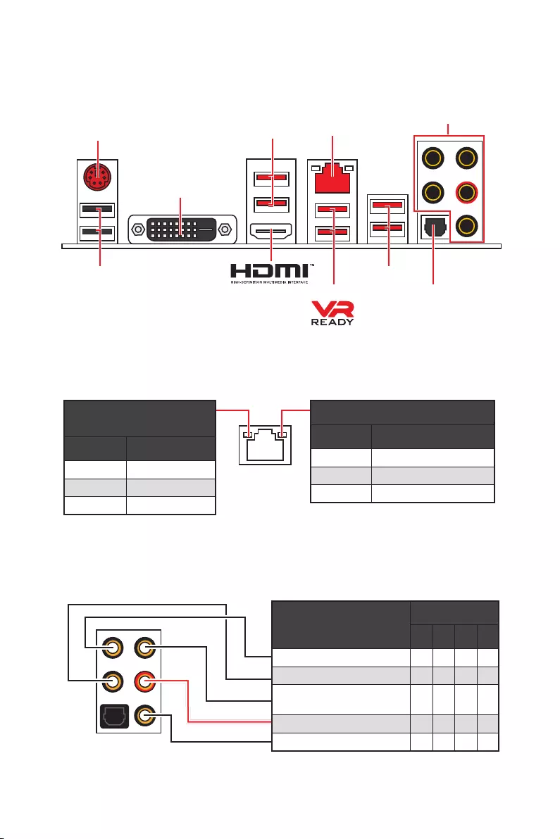
9
Panneau arrière Entrée / Sortie
Configuration des ports audio
Ports audio Canal
2468
Sortie centre / Caisson de basse ● ●
Sortie audio haut-parleur arrière ●●●
Entrée Ligne / Sortie audio haut-
parleur côté ●
Sortie Ligne / Sortie casque avant ●●●●
Entrée Microphone
(● : connecté, Espace : vide)
Panneau arrière Entrée / Sortie
LAN
USB 2.0
PS/2
Ports audio
Sortie S / PDIF optique
USB 3.2 Gen1
USB 3.2 Gen1
USB 3.2 Gen2
LED indiquant la connexion
et l’activité
Etat Description
Eteint Pas de connexion
Jaune Connexion correcte
Clignote Activité en cours
LED indiquant la vitesse
Etat Description
Eteint Débit de 10 Mbps
Vert Débit de 100 Mbps
Orange Débit de 1 Gbps
Tableau explicatif de l’état de la LED du port LAN
DVI-D

10 Panneau arrière Entrée / Sortie
Realtek HD Audio Manager
Après l’installation du pilote Realtek HD Audio, l’icône Realtek HD Audio Manager
apparaît dans la barre des tâches du système. Double-cliquez sur l’icône pour lancer
le programme.
ySélection du périphérique — vous permet de sélectionner une source de sortie
audio pour en modifier les paramètres. Le symbole de coche indique le périphérique
sélectionné par défaut.
yAmélioration d’application — les diverses options vous fournissent un guide complet
des effets acoustiques proposés pour les périphériques de sortie et d’entrée.
yVolume principal — contrôle le volume ou équilibre le son gauche / droite des haut-
parleurs branchés sur le panneau avant ou derrière en ajustant la barre de volume.
yProfils — bascule entre les profils.
yParamètres avancés — fournit le mécanisme pour gérer deux flux audio
indépendants.
yEtat des prises Jack — présente tous les périphériques de diffusion et de capture
connectés à votre ordinateur.
yParamètres du connecteur — configure les paramètres de connexion.
Dialogue popup automatique
Lorsqu’un périphérique est branché sur une prise audio, une fenêtre de dialogue
apparaîtet vous demande de choisir le périphérique connecté que vous souhaitez
utiliser.
Chaque jack est réglé avec ses paramètres par défaut comme indiqué sur la page
suivante.
Etat des
prises Jack
Sélection du
périphérique
Paramètres du
connecteur
Profils
Volume
principal
Amélioration
d’application
Paramètres
avancés

11
Panneau arrière Entrée / Sortie
AUDIO INPUT
Rear Front
Side Center/
Subwoofer
Illustration de l’utilisation des ports audio dédiés au casque et au
microphone
Illustration de l’utilisation du port audio dédié aux haut-parleurs
Illustration de l’utilisation des ports audio dédiés aux haut-parleurs 7.1
AUDIO INPUT

12 Vue d’ensemble des composants
Vue d’ensemble des composants
SATA▼3▲4
SATA▼1▲2
SATA▼5▲6
CPU_FAN1
JRGB1
JRGB2
PUMP_FAN1
PCI_E1
PCI_E2
PCI_E3
PCI_E4
PCI_E5
PCI_E6
JTPM1
Socket processeur
CPU_PWR1
CPU_PWR2
JBAT1
M2_2
M2_1
DIMMA1
SYS_FAN1
DIMMA2
DIMMB1
DIMMB2
JLPT1
JUSB1
JUSB2
JFP2
JFP1
JAUD1
ATX_PWR1
SYS_FAN3
SYS_FAN4
SYS_FAN2
Clear CMOS
JCOM1
JUSB4
JCI1
JUSB3
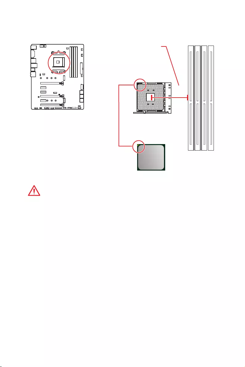
13
Vue d’ensemble des composants
Socket processeur
Présentation du socket AM4
Sur le socket AM4, vous remarquerez
un triangle jaune servant d’indicateur
pour placer le processeur dans la
bonne position sur la carte mère. Le
triangle jaune correspond à la broche
1 du processeur.
Important
y
Lorsque vous changez le processeur, il se peut que la configuration du système
soit effacée et que le BIOS soit réinitialisé à ses valeurs par défaut en raison de
l’architecture du processeur AM4.
y
Avant d’installer ou de retirer le processeur du socket, veuillez à toujours
débrancher le câble d’alimentation de la prise électrique.
y
Lors de l’installation d’un processeur, n’oubliez pas d’installer un ventilateur pour
processeur. Un ventilateur de processeur est nécessaire pour protéger le processeur
contre la surchauffe et maintenir la stabilité du système.
y
Assurez-vous de l’étanchéité entre le ventilateur et le processeur avant de démarrer
votre système.
y
La surchauffe peut facilement endommager le processeur et la carte mère.
Assurez-vous toujours que le système de refroidissement fonctionne correctement
pour protéger le processeur de la surchauffe. Assurez-vous d’appliquer une couche
de pâte thermique (ou adhésif thermique) entre le processeur et le système de
refroidissement afin d’améliorer la dissipation de la chaleur.
y
Si vous avez achetez un processeur indépendamment du ventilateur, veuillez vous
référer à la documentation dans le paquet du ventilateur pour plus d’informations
concernant l’installation.
y
Cette carte mère supporte l’overclocking. Néanmoins, veuillez vous assurer que vos
composants soient capables de tolérer l’overclocking. Prenez note que l’utilisation
au-delà des spécifications du constructeur n’est pas recommandée. MSI
®
ne garantit
pas les dommages et risques causés par les utilisations non prévues dans les
spécifications du produit.
53.43
mm
Distance entre le centre du CPU
et le slot DIMM le plus proche.
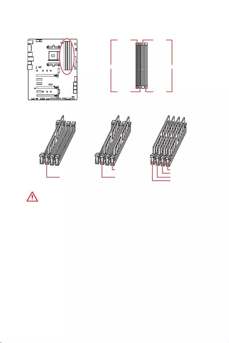
14 Vue d’ensemble des composants
Slots DIMM
Important
y
Veillez à toujours insérer un module de mémoire dans l’emplacement DIMMA2 en
premier.
y
Du fait des ressources utilisées par le chipset, la capacité de mémoire disponible est
un peu moins élevée que celle installée.
y
Basé sur les spécifications du processeur, une tension d’une barrette mémoire en
dessous de 1.35V est conseillée pour protéger le processeur.
y
Certaines mémoires peuvent fonctionner à une fréquence réduite par rapport à
la valeur indiquée lors de l’overclocking car la fréquence d’opération de mémoire
dépend du Serial Presence Detect (SPD). Rendez-vous sur le BIOS et choisissez la
fonction DRAM Frequency pour régler la fréquence de mémoire si vous voulez faire
fonctionner la mémoire à la fréquence indiquée ou à une fréquence plus élevée.
y
Il est recommandé d’utiliser un système de refroidissement qui sera capable de
refroidir toutes les barrettes mémoire et d’offrir de bonnes performances lors d’un
overclocking.
y
La stabilité et la compatibilité du module de mémoire lors de l’overclocking
dépendent du processeur et des périphériques installés.
y
Du fait des limites officiels des spécifications du contrôleur CPU / mémoire AM4, les
modules de mémoire peuvent fonctionner à une fréquence réduite par rapport à la
valeur indiquée en mode défaut. Veuillez vous référer au site www.msi.com pour plus
d’informations sur la mémoire compatible.
DIMMA1 DIMMB1
Canal A Canal B
DIMMA2 DIMMB2
Installation recommandée de module mémoire
DIMMB2 DIMMB2
DIMMB1
DIMMA2 DIMMA2 DIMMA2
DIMMA1
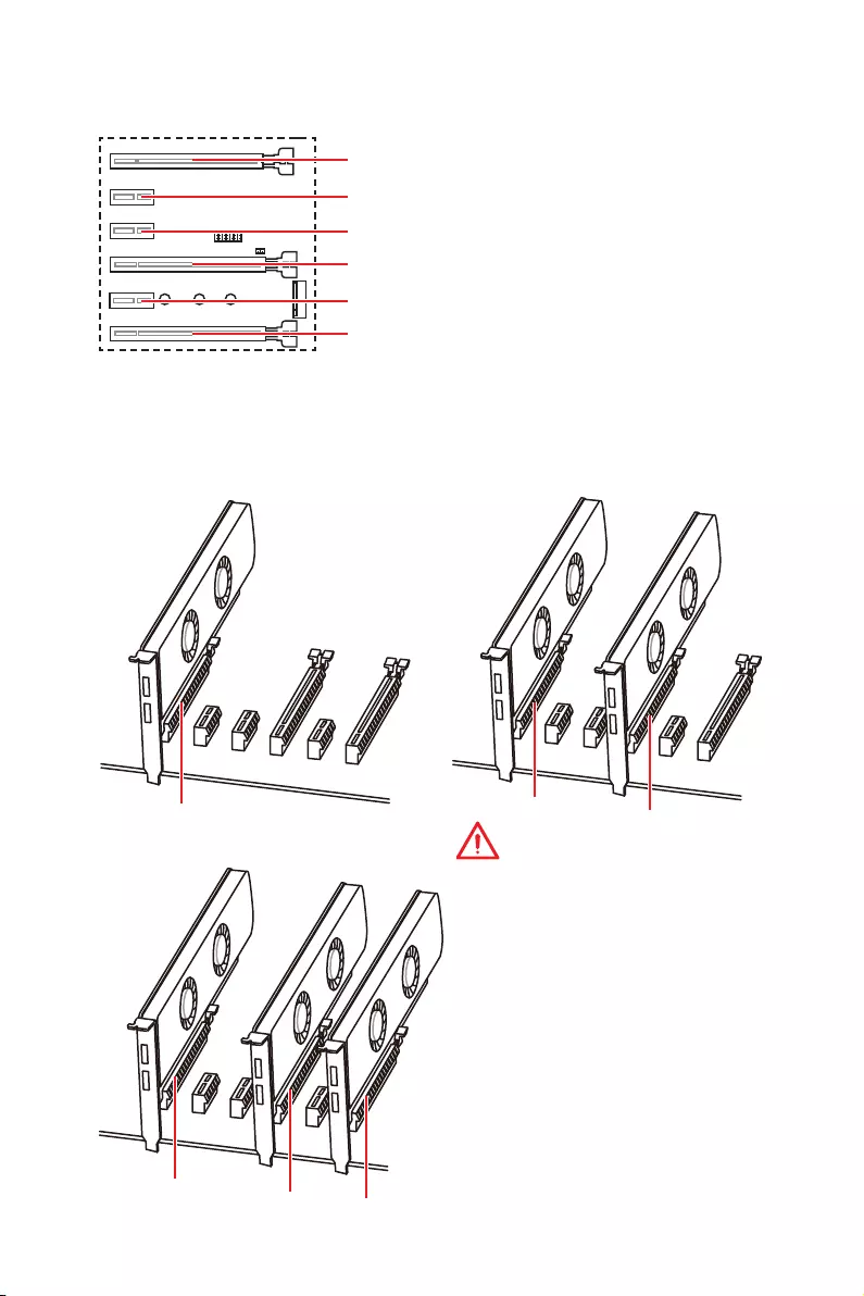
15
Vue d’ensemble des composants
Important
y
Si vous installez une carte graphique
lourde, il vous faut utiliser un outil
comme la barre de support MSI
Gaming Series pour supporter son
poids et pour éviter la déformation du
slot.
y
Si vous choisissez d’installer une
seule carte d’extension PCIe x 16, nous
vous recommandons d’utiliser le slot
PCI_E1 pour profiter de performances
optimales.
y
Veillez à toujours mettre l’ordinateur
hors tension et à débrancher le cordon
d’alimentation avant d’installer les
cartes d’extension. Référez-vous à la
documentation des cartes pour vérifier
si un composant ou un logiciel doit être
modifié.
PCI_E4 : PCIe 3.0 x 8* / Indisponible** / Indisponible***
PCI_E1~6 : Slots d’extension PCIe
PCI_E2 : PCIe 2.0 x 1
PCI_E3 : PCIe 2.0 x 1
PCI_E5 : PCIe 2.0 x 1
PCI_E6 : PCIe 2.0 x 4
Installation recommandée pour une configuration multi-GPU (Processeurs
des séries Ryzen™)
x 16 x 8
x 8
x 8
x 8 x 4
PCI_E1 : PCIe 3.0 x 16* / PCIe 3.0 x 8** / PCIe 3.0 x 4***
* Pour les processeurs AMD Ryzen™ de 1ère, 2ème et 3ème génération
** Pour les processeurs Ryzen™ avec cœurs graphiques Radeon™ Vega et AMD
Ryzen™ avec cœurs graphiques Radeon™ de 2ème génération
*** Pour les processeurs Athlon™ avec cœurs graphiques Radeon™ Vega

16 Vue d’ensemble des composants
Tableau de la bande passante du PCle
Pour les processeurs AMD Ryzen™ de 1ère, 2ème et 3ème génération
Slot Unique 2-Way
PCI_E1 (CPU) Gen 3.0 x 16* Gen 3.0 x 8*
PCI_E2 (PCH) Gen 2.0 x 1 Gen 2.0 x 1
PCI_E3 (PCH) Gen 2.0 x 1 Gen 2.0 x 1
PCI_E4 (CPU) ─Gen 3.0 x 8*
PCI_E5 (PCH) Gen 2.0 x 1 Gen 2.0 x 1
PCI_E6 (PCH) Gen 2.0 x 4 ─Gen 2.0 x 4 ─
M2_1 (CPU) Gen 3.0 x 4 Gen 3.0 x 4
M2_2 (PCH) ─Gen 2.0 x 4 ─Gen 2.0 x 4
(─ : indisponible, * : carte graphique)
Pour les processeurs Ryzen™ avec cœurs graphiques Radeon™ Vega et AMD
Ryzen™ avec cœurs graphiques Radeon™ de 2ème génération
Slot Unique
PCI_E1 (CPU) Gen 3.0 x 8*
PCI_E2 (PCH) Gen 2.0 x 1
PCI_E3 (PCH) Gen 2.0 x 1
PCI_E4 (CPU) ─
PCI_E5 (PCH) Gen 2.0 x 1
PCI_E6 (PCH) Gen 2.0 x 4 ─
M2_1 (CPU) Gen 3.0 x 4
M2_2 (PCH) ─Gen 2.0 x 4
(─ : indisponible, * : carte graphique)
Pour les processeurs Athlon™ avec cœurs graphiques Radeon™ Vega
Slot Unique
PCI_E1 (CPU) Gen 3.0 x 4*
PCI_E2 (PCH) Gen 2.0 x 1
PCI_E3 (PCH) Gen 2.0 x 1
PCI_E4 (CPU) ─
PCI_E5 (PCH) Gen 2.0 x 1
PCI_E6 (PCH) Gen 2.0 x 4 ─
M2_1 (CPU) Gen 3.0 x 2
M2_2 (PCH) ─Gen 2.0 x 4
(─ : indisponible, * : carte graphique)
Important
Le slot PCI_E6 est indisponible lorsqu’un SSD PCIe M.2 est installé dans le slot M2_2.

17
Vue d’ensemble des composants
M2_1~2 : Slots M.2 (Touche M)
Vidéo de démonstration
Référez-vous à la vidéo d’instruction sur l’installation du SSD M.2.
http://youtu.be/JCTFABytrYA
Installation du SSD M.2
30°
2. Déplacez et fixez la vis
M.2 à l’emplacement
approprié selon la taille
de votre SSD M.2.
3. Insérez votre SSD M.2
dans le slot M.2 à un
angle de 30 degrés.
4. Fixez le SSD M.2 avec la
vis M.2 fournie.
1. Desserrez la vis M.2 de
la carte mère.
Vis M.2 fournie
Important
y
Le port SATA1 est indisponible lorsqu’un SSD SATA M.2
est installé dans le slot M2_2.
y
Le slot PCI_E6 est indisponible lorsqu’un SSD PCIe M.2
est installé dans le slot M2_2.
y
Le slot M2_1 supporte seulement le mode PCIe.
M2_1
M2_2

18 Vue d’ensemble des composants
SATA1~6 : Connecteurs SATA 6 Gb/s
Ces connecteurs utilisent une interface SATA 6 Gb/s. Chaque connecteur peut être
relié à un appareil SATA.
SATA5
SATA3
SATA1
SATA6
SATA4
SATA2
Important
y
Le port SATA1 est indisponible lorsqu’un SSD SATA M.2 est installé dans le slot
M2_2.
y
Veuillez ne pas plier les câbles SATA à 90° car cela pourrait entraîner une perte de
données pendant la transmission.
y
Les câbles SATA disposent de prises identiques sur chaque côté. Néanmoins, il est
recommandé de connecter la prise plate sur la carte mère pour un gain d’espace.
1
2 26
25
1 RSTB# 2 AFD# 3 PRND0
4 ERR# 5 PRND1 6 PINIT#
7 PRND2 8 LPT_SLIN# 9 PRND3
10 Ground 11 PRND4 12 Ground
13 PRND5 14 Ground 15 PRND6
16 Ground 17 PRND7 18 Ground
19 ACK# 20 Ground 21 BUSY
22 Ground 23 PE 24 Ground
25 SLCT 26 No Pin
JLPT1 : Connecteur de port parallèle
Ce connecteur sert à connecter un support de port parallèle optionnel.
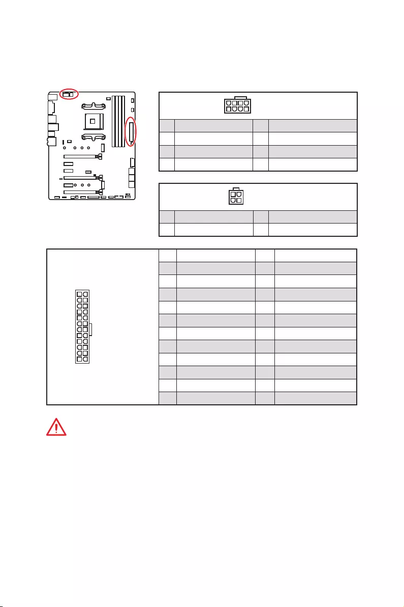
19
Vue d’ensemble des composants
24
131
12
ATX_PWR1
1 +3.3V 13 +3.3V
2 +3.3V 14 -12V
3 Ground 15 Ground
4 +5V 16 PS-ON#
5 Ground 17 Ground
6 +5V 18 Ground
7 Ground 19 Ground
8 PWR OK 20 Res
9 5VSB 21 +5V
10 +12V 22 +5V
11 +12V 23 +5V
12 +3.3V 24 Ground
5
4 1
8CPU_PWR1
1 Ground 5 +12V
2 Ground 6 +12V
3 Ground 7 +12V
4 Ground 8 +12V
Important
Veuillez vous assurer que tous les câbles d’alimentation sont branchés aux
connecteurs adéquats afin garantir une opération stable de la carte mère.
CPU_PWR1, CPU_PWR2, ATX_PWR1 : Connecteurs
d’alimentation
Ces connecteurs vous permettent de relier une alimentation ATX.
3
2 1
4CPU_PWR2
1 Ground 3 +12V
2 Ground 4 +12V
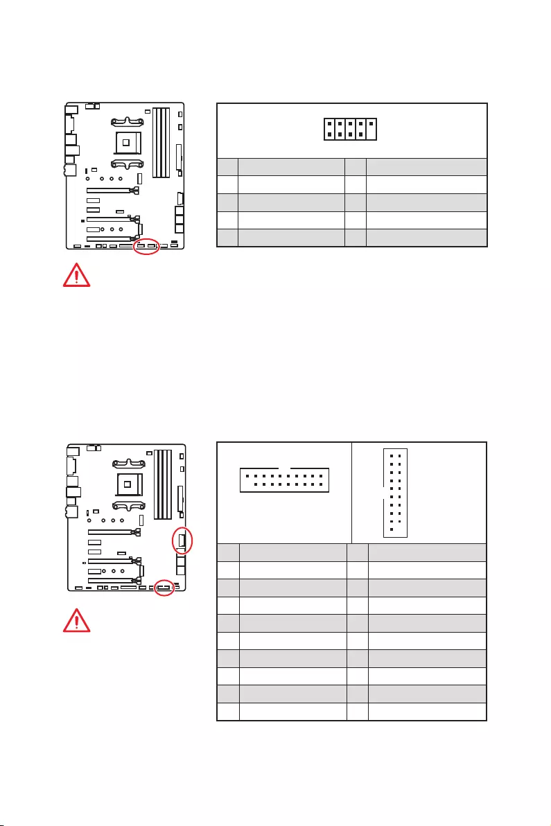
20 Vue d’ensemble des composants
JUSB3~4 : Connecteurs USB 3.2 Gen1
Ces connecteurs vous permettent de relier un port USB 3.2 Gen1 sur le panneau
avant.
Important
Notez que les câbles
d’alimentation et de terre
doivent être branchés
correctement afin d’éviter
d’endommager la carte.
1 10
1120
JUSB3
1
10 11
20
JUSB4
1Power 11 USB2.0+
2 USB3_RX_DN 12 USB2.0-
3 USB3_RX_DP 13 Ground
4 Ground 14 USB3_TX_C_DP
5 USB3_TX_C_DN 15 USB3_TX_C_DN
6 USB3_TX_C_DP 16 Ground
7 Ground 17 USB3_RX_DP
8 USB2.0- 18 USB3_RX_DN
9 USB2.0+ 19 Power
10 NC 20 No Pin
JUSB1~2 : Connecteurs USB 2.0
Ces connecteurs vous permettent de relier des ports USB 2.0 sur le panneau avant.
1
2 10
9
1VCC 2VCC
3 USB0- 4 USB1-
5 USB0+ 6 USB1+
7 Ground 8 Ground
9 No Pin 10 NC
Important
y
Notez que les broches VCC et Terre doivent être branchées correctement afin
d’éviter tout dommage sur la carte mère.
y
Pour recharger votre iPad, iPhone et iPod par l’intermédiaire d’un port USB,
veuillez installer l’utilitaire MSI
®
SUPER CHARGER.

21
Vue d’ensemble des composants
Important
Veuillez vous assurer que les ventilateurs fonctionnent correctement après avoir
basculé entre les modes PWM et DC.
CPU_FAN1, PUMP_FAN1, SYS_FAN1~4 : Connecteurs pour
ventilateurs
Les connecteurs pour ventilateurs peuvent être utilisés en mode PWM (Pulse Width
Modulation) et en mode DC. En mode PWM, les connecteurs fournissent une sortie
de 12V constante et ajustent la vitesse des ventilateurs avec un signal de contrôle
de vitesse. En mode DC, les connecteurs contrôlent la vitesse des ventilateurs en
modifiant la tension. Quand vous branchez un ventilateur à 3 broches (Non-PWM)
à un connecteur de ventilateur de mode PWM, la vitesse sera toujours maintenue
à 100% et cela occasionnera du bruit. CPU_FAN1 et PUMP_FAN1 peuvent détecter
automatiquement le mode PWM et le mode DC. Vous pouvez suivre les instructions
ci-dessous pour régler le connecteur de ventilateur en mode PWM ou mode DC.
Définition des broches en mode PWM
1 Ground 2 +12V
3 Sense 4 Speed Control Signal
Définition des broches en mode DC
1 Ground 2 Voltage Control
3 Sense 4 NC
Connecteurs pour ventilateurs en mode
PWM par défaut
Connecteurs pour ventilateurs en mode
DC par défaut
Basculer entre les modes des ventilateurs et ajuster la vitesse
Vous pouvez alterner entre le mode PWM et le mode DC et ajuster la vitesse des
ventilateurs dans le BIOS > HARDWARE MONITOR.
Choisissez le mode PWM, le mode DC ou le mode Auto
Il y a des points de gradient de la vitesse du ventilateur qui
vous permet d’ajuster la vitesse de ventilateur par rapport à la
température du processeur.
1
SYS_FAN1 / SYS_FAN3 / SYS_FAN4
1
SYS_FAN2
1
CPU_FAN1
Définition des broches des connecteurs de ventilateur
Connecteurs pour ventilateurs en mode
Auto par défaut
1
PUMP_FAN1
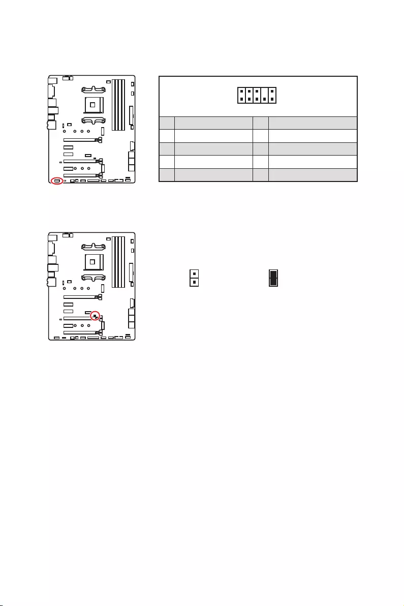
22 Vue d’ensemble des composants
JAUD1 : Connecteur audio avant
Ce connecteur se lie aux jacks audio du panneau avant.
1
2 10
9
1 MIC L 2 Ground
3 MIC R 4 NC
5 Head Phone R 6 MIC Detection
7 SENSE_SEND 8 No Pin
9 Head Phone L 10 Head Phone Detection
JCI1 : Connecteur intrusion châssis
Ce connecteur est relié à un câble d’interrupteur intrusion châssis.
Normal
(défaut)
Commencer l’activité
intrusion châssis
Utilisation du détecteur d’intrusion châssis
1. Reliez le connecteur JCI1 à l’interrupteur ou au capteur d’intrusion châssis situé
sur le boîtier du PC.
2. Fermez le couvercle du boîtier.
3. Allez dans le BIOS > SETTINGS (Réglages) > Security (Sécurité) > Chassis
Intrusion Configuration (Configuration intrusion châssis).
4. Réglez Chassis Intrusion (intrusion châssis) sur Enabled (Activé).
5. Appuyez sur F10 pour sauvegarder et quitter. Ensuite appuyez sur la touche Enter
(Entrée) pour choisir Yes (Oui).
6. Désormais, si le boîtier du PC est ouvert quand l’ordinateur est allumé, vous
recevrez un message d’alerte à l’écran.
Réinitialisation de l’alerte intrusion châssis
1. Allez dans le BIOS > SETTINGS (Réglages) > Security (Sécurité) > Chassis
Intrusion Configuration (Configuration intrusion châssis).
2. Mettez Chassis Intrusion (Intrusion châssis) en Reset (Remettre).
3. Appuyez sur F10 pour sauvegarder et quitter. Ensuite appuyez sur la touche Enter
(Entrée) pour choisir Yes (Oui).

23
Vue d’ensemble des composants
1
2 14
13
1 LPC Clock 2 3V Standby power
3 LPC Reset 4 3.3V Power
5 LPC address & data pin0 6 Serial IRQ
7 LPC address & data pin1 8 5V Power
9 LPC address & data pin2 10 No Pin
11 LPC address & data pin3 12 Ground
13 LPC Frame 14 Ground
JTPM1 : Connecteur de module TPM
Ce connecteur est relié à un module TPM (Trusted Platform Module). Veuillez vous
référer au manuel du module TPM pour plus d’informations.
JFP1, JFP2 : Connecteurs de panneau avant
Ces connecteurs se lient aux interrupteurs et indicateurs LED du panneau avant.
1
2 10
9
JFP1
1 HDD LED + 2 Power LED +
3 HDD LED — 4 Power LED —
5 Reset Switch 6 Power Switch
7 Reset Switch 8 Power Switch
9 Reserved 10 No Pin
1
JFP2
1 Speaker — 2 Buzzer +
3 Buzzer — 4 Speaker +

24 Vue d’ensemble des composants
JRGB1, JRGB2 : Connecteurs LED RGB
Le connecteur JRGB1 / JRGB2 vous permet de connecter un ruban LED RGB de type
5050 12V et un ventilateur CPU AMD avec LED RGB.
Important
y
Le connecteur JRGB1 / JRGB2 supporte des rubans LED RGB (12V / G / R / B) de type
5050 avec une puissance nominale maximale de 3A (12V).
y
Veuillez garder la longueur du ruban LED inférieure à 2 mètres pour éviter la
gradation des couleurs.
y
Avant d’installer ou de retirer le ruban LED RGB, veillez à toujours éteindre
l’alimentation et à débrancher le câble d’alimentation de la prise électrique.
y
Veuillez utiliser un logiciel MSI dédié pour contrôler le ruban d’extension LED.
1
JRGB1 / JRGB2
JRGB1
JRGB2 Câble d’extension Ruban LED RGB de type
5050, sortie 12V
1
JRGB1
JRGB2
1 +12V 2 G
3 R 4 B
1
2 10
9
1 DCD 2 SIN
3 SOUT 4 DTR
5 Ground 6 DSR
7 RTS 8 CTS
9 RI 10 No Pin
JCOM1 : Connecteur de port série
Ce connecteur vous permet de relier un port série en option.
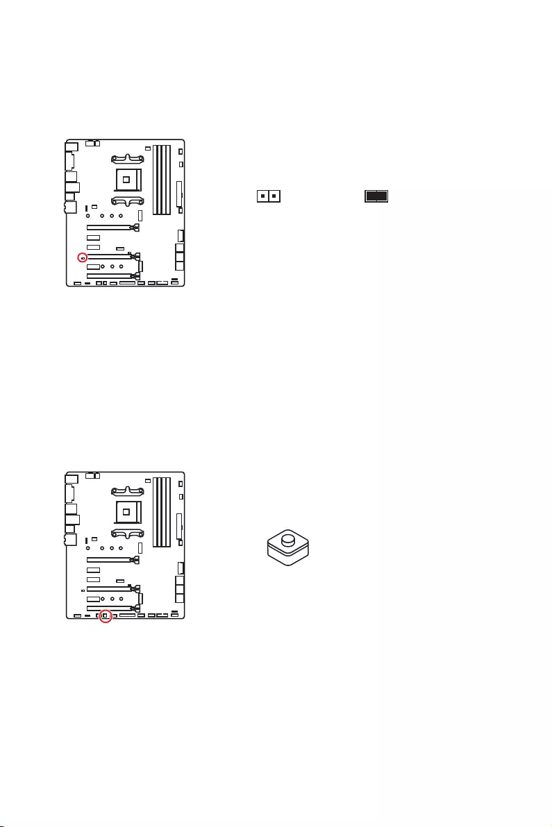
25
Vue d’ensemble des composants
JBAT1 : Cavalier Clear CMOS (Réinitialisation BIOS)
Une mémoire CMOS est intégrée et est alimentée en externe par une batterie située
sur la carte mère afin de conserver les données de configuration système. Si vous
souhaitez nettoyer la configuration système, placez le cavalier sur Effacer CMOS de
manière à nettoyer la mémoire CMOS.
Conserver
les données
(défaut)
Effacer CMOS /
Réinitialiser BIOS
Réinitialiser le BIOS aux valeurs par défaut
1. Eteignez l’ordinateur et débranchez le câble d’alimentation de la prise électrique.
2. Utilisez un couvercle de cavalier pour fermer JBAT1 pour environ 5-10 secondes.
3. Enlevez le couvercle de cavalier du JBAT1.
4. Branchez de nouveau le câble d’alimentation à votre ordinateur et allumez-le.
CLR_CMOS1 : Bouton Clear CMOS
Eteignez votre ordinateur. Appuyez sur le bouton CMOS pendant environ 5-10 secondes
pour remettre le BIOS aux valeurs par défaut.
Bouton Clear CMOS

26 Configuration du BIOS
Configuration du BIOS
Les réglages par défaut fournissent une performance optimale pour la stabilité du
système en conditions normales. Veillez à toujours garder les réglages par défaut
pour éviter d’endommager le système ou tout problème au démarrage, sauf si vous
êtes familier avec le BIOS.
Important
y
Le BIOS est constamment mis à jour afin d’offrir de meilleures performances
système. Par conséquent, la description peut différer selon la version de BIOS utilisée
et n’est donc donnée qu’à titre de référence. Vous pouvez aussi vous référer à
l’onglet Help (Aide) pour obtenir la description des fonctions du BIOS.
y
Les photos ne sont données qu’à titre de référence et peuvent varier selon le produit
que vous achetez.
Entrer dans l’interface Setup du BIOS
Pendant le démarrage, lorsqu’apparaît le message “Press DEL key to enter Setup
Menu, F11 to enter Boot Menu” sur l’écran, veuillez appuyer sur la touche Suppr.
Touches de fonction
F1 : Aide générale
F2 : Ajouter ou supprimer un élément favori
F3 : Entrer dans le menu Favoris
F4 : Entrer dans le menu de réglages du processeur
F5 : Entrer dans le menu Memory-Z
F6 : Charger les réglages par défaut
F7 : Alterner entre le mode avancé et le mode simplifié
F8 : Charger le profil d’overclocking
F9 : Sauvegarder le profil d’overclocking
F10 : Sauvegarder les modifications et réglages*
F12 : Prendre une capture d’écran et la conserver dans le lecteur flash USB (au
format FAT / FAT32 uniquement).
Ctrl+F: Entrer dans la page de recherche
* Lorsque vous appuyez sur F10, une fenêtre de confirmation apparaît et fournit
l’information de modification. Choisissez entre Oui et Non pour confirmer.

27
Configuration du BIOS
Réinitialiser le BIOS
Il se peut que vous ayez besoin de récupérer les réglages BIOS par défaut pour
résoudre des problèmes. Pour réinitialiser les réglages du BIOS, veuillez suivre l’une
des méthodes suivantes :
yAllez dans le Setup du BIOS et appuyez sur F6 pour charger les réglages par défaut.
yCourt-circuitez le cavalier Clear CMOS sur la carte mère.
Important
Assurez-vous que l’ordinateur est éteint avant d’effacer les données CMOS. Veuillez
vous référer à la section cavalier Clear CMOS pour en savoir plus sur la réinitialisation
du BIOS.
Mettre le BIOS à jour
Mettre le BIOS à jour avec M-FLASH
Avant la mise à jour :
Veuillez télécharger la dernière version de BIOS compatible à votre carte mère sur le
site MSI. Ensuite, veuillez sauvegarder le nouveau BIOS sur le lecteur flash USB.
Mettre le BIOS à jour :
1. Connectez le lecteur Flash USB contenant le profil à l’ordinateur.
2. Appuyez sur la touche <Ctrl+F5> pendant le processus de POST.
3. Cliquez sur Yes (Oui) pour redémarrer le système et entrer dans le mode Flash.
4. Choisissez un profil BIOS pour commencer la mise à jour du BIOS.
5. Une fois la mise à jour terminée, le système redémarrera automatiquement.
Mettre le BIOS à jour avec Live Update 6
Avant la mise à jour :
Assurez-vous que le lecteur LAN est bien installé et que l’ordinateur est correctement
connecté à internet.
Mettre le BIOS à jour :
1. Installez et lancez MSI LIVE UPDATE 6.
2. Choisissez BIOS Update (Mettre le BIOS à jour).
3. Cliquez sur le bouton Scan.
4. Cliquez sur l’icône Download pour télécharger et installer la dernière version du
BIOS.
5. Cliquez sur Next (Suivant) et choisissez le mode In Windows. Ensuite, cliquez sur
Next (Suivant) et Start (Commencer) pour lancer la mise à jour du BIOS.
6. Une fois la mise à jour terminée, le système redémarrera automatiquement.
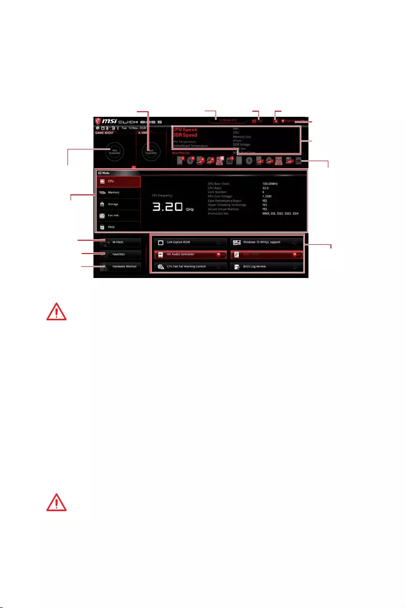
28 Configuration du BIOS
EZ Mode (mode simplifié)
Le mode EZ vous fournit les informations basiques du système et vous permet
de configurer les réglages de base. Si vous souhaitez configurer les réglages du
BIOS, veuillez utiliser le mode Advanced en appuyant sur le switch Setup Mode
(Interrupteur de modes de réglages) ou la touche de fonction F7.
Ecran
d’informations
Informations
du système
Barre priorité
de périphérique
démarrage
Boutons de
fonction
Langue
Recherche
Capture
d’écran
Interrupteur de
modes de réglages
M-Flash
Favoris
Moniteur de
matériel
Interrupteur
GAME BOOST
Interrupteur A-XMP
yInterrupteur GAME BOOST — appuyez sur le bouton GAME BOOST pour activer cette
fonctionnalité.
Important
Après l’activation de la fonction GAME BOOST, il est conseillé de ne faire aucune
modification dans menu OC et de ne pas charger les réglages par défauts pour
conserver des performances optimales et une bonne stabilité du système.
yInterrupteur A-XMP (en option) — cliquez sur le cercle intérieur pour activer ou
désactiver le profil A-XMP. Cliquez sur le cercle extérieur pour choisir le profil XMP
s’il y en a. Cet interrupteur est seulement disponible si le processeur et le module de
mémoire installés prennent cette fonction en charge.
yInterrupteur de modes de réglages — appuyez sur ce menu ou la touche F7 pour
commuter entre le mode avancé et le mode simplifié.
yCapture d’écran — appuyez sur ce menu ou sur la touche F12 pour prendre une
capture d’écran et la conserver dans le lecteur flash USB (lecteur flash USB au
format FAT ou FAT32 uniquement).
yRecherche — cliquez sur cet onglet ou sur les touches Ctrl+F pour faire apparaître
la page de recherche. Cette page vous permet de faire des recherche en utilisant les
noms des éléments du BIOS. Entrez le nom de l’élément et vous le trouverez ensuite
dans la liste qui s’affichera alors. Déplacez la souris sur un espace vierge et faites un
clic droit pour quitter la page de recherche.
Important
Dans la page de recherche, seules les touches de fonction F6, F10 et F12 sont
disponibles.
yLangue — vous permet de choisir la langue du BIOS.

29
Configuration du BIOS
yInformations du système — montre la vitesse et la tension du processeur et de la
mémoire, la température du processeur et de la carte mère, le type de carte mère et
de processeur, la capacité mémoire, la version du BIOS et la date d’installation.
yBarre priorité de périphérique démarrage — vous pouvez déplacer les icônes dédiés
aux périphériques pour modifier la priorité au démarrage. Le sens de la priorité va de
gauche à droite.
yEcran d’informations — cliquez sur les boutons CPU (Processeur), Memory
(Mémoire), Storage (Stockage), Fan Info (Info ventilateurs) et Help (Aide) à gauche
de la fenêtre pour obtenir les informations respectives.
yBoutons de fonction — en cliquant sur leur bouton respectif, vous pourrez activer
les fonctionsLAN Option ROM, HD audio controller, Window 10 WHQL Support, AHCI,
RAID, CPU Fan Fail Warning Control et BIOS Log Review.
Important
y
Pendant la configuration de Windows, le pilote RAID peut être requis et vous pouvez
le trouver dans le disque des pilotes MSI.
y
Vous pouvez utiliser MSI SMART TOOL pour créer un support d’installation
Windows
®
, qui comprendra le pilote RAID.
y
Si vous avez réglé le SSD M.2 en RAID comme disque de démarrage du système et
que vous avez supprimé la configuration RAID dans le BIOS UEFI, votre système ne
démarrera pas.
yM-Flash — cliquez sur ce bouton pour faire apparaître le menu M-Flash qui fournit la
méthode de mise à jour BIOS à l’aide d’un disque flash USB.
yMoniteur de matériel — cliquez sur ce bouton pour faire apparaître le menu Moniteur
de matériel qui vous permet de contrôler manuellement la vitesse des ventilateurs.
yFavoris — appuyez sur l’onglet Favoris ou appuyez sur la touche F3 pour entrer dans
le menu Favoris. Il vous permet de créer un menu BIOS personnalisé où vous pourrez
sauvegarder et accéder à vos réglages favoris ou fréquemment utilisés.
Default Homepage (page d’accueil par défaut) — vous permet de choisir l’un des
menus du BIOS (par exemple, Réglages, OC, etc.) comme page d’accueil.
Favorite 1 ~ 5 (Favoris 1 ~ 5) — vous permettent d’afficher les menus de réglages
BIOS fréquemment utilisés ou les favoris sur une seule page.
Ajouter les menus BIOS sur une seule page des favoris (Favoris 1~5)
1. Déplacez la souris sur un élément du BIOS, pas seulement dans le menu du
BIOS mais également sur la page de recherche.
2. Faites un clic droit ou appuyez sur la touche F2.
3. Choisissez une page de favoris et cliquez sur OK.
Supprimer un paramètre du BIOS de la page des favoris
1. Déplacez la souris sur un élément du BIOS sur la page des favoris (Favoris
1~5).
2. Faites un clic droit ou appuyez sur la touche F2.
3. Choisissez Delete (Effacer) et cliquez sur OK.
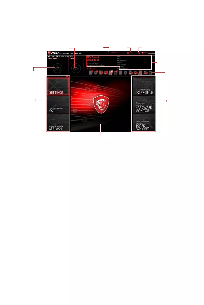
30 Configuration du BIOS
Advanced Mode (mode avancé)
Appuyez sur le Setup Mode switch (interrupteur de modes de réglages) ou sur la
touche de fonction F7 pour commuter entre le mode simplifié et le mode avancé.
Interrupteur A-XMP
Interrupteur
GAME BOOST
Information
du système
Barre priorité
de périphérique
démarrage
Sélection du
menu BIOS
Langue
Recherche
Capture
d’écran
Interrupteur de
modes de réglages
Ecran de menu
Sélection du
menu BIOS
yInterrupteur GAME BOOST / Interrupteur de modes de réglages / Capture d’écran
/ Favoris / Langue / Information du système / Barre priorité de périphérique
démarrage — veuillez vous référer à la partie EZ mode pour plus de précision.
ySélection du menu BIOS — les options suivantes sont disponibles :
SETTINGS (Réglages) — permet de personnaliser les paramètres du chipset et du
démarrage des périphériques.
OC — permet d’ajuster la fréquence et la tension. L’augmentation de la fréquence
peut améliorer les performances.
M-FLASH — permet de mettre le BIOS à jour avec un lecteur flash USB.
OC PROFILE — permet de gérer les profils d’overclocking.
HARDWARE MONITOR (Moniteur de matériel) — permet de régler la vitesse des
ventilateurs et de surveiller la tension du système.
BOARD EXPLORER — fournit des informations sur les périphériques installés sur
la carte mère.
yEcran de menu — affiches les menus de réglages BIOS et les informations à
configurer.

31
Configuration du BIOS
OC Menu (menu overclocking)
Ce menu est destiné aux utilisateurs avancés souhaitant overclocker leur carte mère.
Important
y
L’overclocking manuel du PC n’est recommandé que pour les utilisateurs avancés.
y
L’overclocking n’est pas garanti et une mauvaise manipulation peut rendre nulle
votre garantie et sévèrement endommager votre matériel.
y
Si vous n’êtes pas familier avec l’overclocking, nous vous recommandons d’utiliser
GAME BOOST pour un overclocking simplifié et plus stable.
y
Les éléments du BIOS dans le menu OC peuvent varier selon le processeur.
fOC Explore Mode [Normal]
Active ou désactive le mode Normal ou Expert des réglages OC.
[Normal] Fournit les réglages OC standards dans les réglages BIOS.
[Expert] Fournit les réglages OC avancés pour les utilisateurs avancés et à
configurer dans les réglages BIOS.
Remarque : Nous utilisons le symbole * pour indiquer les réglages OC du mode
Expert.
fCPU Ratio [Auto]
Définit le ratio servant à déterminer la vitesse d’horloge du processeur. Ce menu peut
être modifié uniquement si le processeur prend cette fonction en charge.
fCore Performance Boost [Auto]
Active ou désactive la technologie Core Performance Boost (CPB). Ce menu est
seulement disponible si le processeur installé supporte cette fonction.
fDowncore Control [Auto] (en option)
Définir le nombre de coeurs du processeur à utiliser. Ce menu est seulement
disponible si le processeur installé supporte cette fonction.
fA-XMP [Disabled]
Activez la technologie A-XMP ou sélectionnez un profil de module de mémoire
pour overclocker la mémoire. Ce menu est seulement disponible si les modules de
mémoire, le processeur ou la carte mère installés prennent cette fonction en charge.

32 Configuration du BIOS
fDRAM Frequency [Auto]
Définit la fréquence de la mémoire. Veuillez noter que les résultats de l’overclocking
ne sont pas garantis.
fMemory Try It ! [Disabled]
Memory Try It! permet d’améliorer la compatibilité ou les performances en optimisant
les préréglages de la mémoire.
fMemory Retry Count [5]
Définit le nombre de tentatives d’overclocking de la mémoire. En cas d’échec, le
réglage de cette valeur sur [5] permettra au système de redémarrer 5 fois avec
la même configuration d’overclocking. Si l’overclocking échoue à chaque fois, le
système réinitialisera la mémoire à ses valeurs par défaut.
fAdvanced DRAM Configuration (en option)
Appuyez sur la touche Entrée pour entrer dans le sous-menu. L’utilisateur
peut régler la synchronisation de mémoire de chaque barrette de mémoire. Le
système peut être instable ou peut ne plus redémarrer après le changement de la
synchronisation de la mémoire. Dans ce cas-là, veuillez effacer les données CMOS
et remettre les réglages par défaut (référez-vous à la section cavalier / bouton Clear
CMOS (en option) pour effacer les données CMOS et entrez ensuite dans le BIOS pour
charger les réglages par défaut).
fDigitALL Power
Appuyez sur la touche Entrée pour entrer dans le sous-menu. Gère l’alimentation
numérique du contrôleur PWM du processeur.
fCPU Loadline Calibration Control [Auto]
La tension du processeur diminue proportionnellement à la charge du processeur.
Une valeur plus élevée peut entraîner une tension plus élevée et de bonnes
performances d’overclocking mais augmentera la température du processeur
et du module de régulation de tension (VRM). Mis en Auto, le BIOS configure ce
réglages automatiquement.
fCPU Over Voltage Protection [Auto]
Définit une limite de tension pour la protection contre la surtension du CPU. En
Auto, le BIOS configure automatiquement ce réglage. Une tension plus élevé
protège moins et peut endommager le système.
fCPU Under Voltage Protection [Auto]
Définit une limite de tension pour la protection contre la sous-tension du CPU.
En Auto, le BIOS configure automatiquement ce réglage. Une tension plus élevée
protège moins et peut endommager le système.
fCPU Over Current Protection [Auto]
Définit une limite actuelle pour la protection contre la surcharge électrique du
CPU. En Auto, le BIOS configure automatiquement ce réglage.
[Auto] Le BIOS configure automatiquement ce réglage.
[Enhanced] Augmente la limite de consommation pour protéger contre la
surcharge électrique.

33
Configuration du BIOS
fCPU Switching Frequency [Auto]
Définit la vitesse de fonction du PWM pour stabiliser la tension du cœur CPU et
minimiser minimize la gamme d’ondulation. L’augmentation de la vitesse de
fonction PWM élève la température MOSFET. Il est nécessaire alors de disposer
d’une solution de refroidissement adéquate pour MOSFET avant d’augmenter
cette valeur. En Auto, le BIOS configure automatiquement ce réglage.
fCPU VRM Over Temperature Protection [Auto]
Régle la limite de température du CPU VRM pour la protection sur-température.
La fréquence CPU peut être restreint lorsque la température CPU dépasse celle
spécifiée. En Auto, le BIOS configurera ce réglage.
fCPU Power Duty Control [Thermal Balance]
Définir la phase VRM et les conditions thermiques de chaque composant de phase.
[Thermal Balance] Maintient l’équilibre thermique du VRM.
[Current Balance] Maintient l’équilibre du courant du VRM.
fCPU NB Loadline Calibration Control [Auto]
La tension du processeur diminue proportionnellement à la charge du CPU-
NB. Une valeur plus élevée peut entraîner une tension plus élevée et de bonnes
performances d’overclocking mais augmentera la température. Mis en Auto, le
BIOS configure ce réglages automatiquement.
fCPU NB Over Current Protection [Auto]
Définit une limite actuelle pour la protection contre la surcharge électrique du CPU
NB. En Auto, le BIOS configure automatiquement ce réglage.
[Auto] Le BIOS configure automatiquement ce réglage.
[Enhanced] Augmente la limite de consommation pour protéger contre la
surcharge électrique.
fCPU NB Switching Frequency [Auto]
Définit la vitesse de fonction du PWM pour stabiliser la tension du CPU NB et
minimiser minimize la gamme d’ondulation. L’augmentation de la vitesse de
fonction PWM élève la température MOSFET. Il est nécessaire alors de disposer
d’une solution de refroidissement adéquate pour MOSFET avant d’augmenter
cette valeur. En Auto, le BIOS configure automatiquement ce réglage.
fCPU NB Power Duty Control [Thermal Balance]
Définir la phase VRM du CPU-NB et les conditions thermiques de chaque
composant de phase.
[Thermal Balance] Maintient l’équilibre thermique du VRM.
[Current Balance] Maintient l’équilibre du courant du VRM.
fVR 12VIN OCP Expander [Auto]
Etendre la limitation de VR Over Current Protection avec la tension d’entrée
de 12V. La valeur d’extension plus haute signifie moins de protection. Par
conséquent, veuillez ajuster le courant soigneusement en cas nécessaire, ou ceci
endommagerait le CPU / VR MOS. Mis en Auto, le BIOS configure ce réglages
automatiquement.
fCPU Voltages control [Auto]
Permet de définir les tensions relatives au processeur. En mode Auto, le BIOS
configure ces tensions automatiquement. Vous pouvez également les paramétrer
manuellement.

34 Configuration du BIOS
fDRAM Voltages control [Auto]
Permet de définir les tensions relatives à la mémoire. En mode Auto, le BIOS
configure ces tensions automatiquement. Vous pouvez également les paramétrer
manuellement.
fMemory Changed Detect [Enabled]*
Active ou désactive les messages d’alerte système au démarrage suite au
remplacement de la mémoire.
[Enabled] Le système montre un message d’alerte pendant le démarrage et vous
devez charger les réglages par défaut pour les nouveaux périphériques.
[Disabled] Désactive cette fonction et garde les réglages BIOS actuels.
fCPU Specifications
Appuyez sur la touche Entrée pour accéder au sous-menu. Ce sous-menu affiche les
caractéristiques du processeur installé. Vous pouvez également accéder à ce sous-
menu à tout moment en appuyant sur la touche [F4]. Fonctionne en lecture seule.
fCPU Technology Support
Appuyez sur la touche Entrée pour accéder au sous-menu. Ce sous-menu affiche
les principales fonctions et technologies prises en charge par le processeur
installé. Fonctionne en lecture seule.
fMEMORY-Z
Appuyez sur la touche Entrée pour accéder au sous-menu. Ce sous-menu affiche tous
les réglages et timings de la mémoire installée. Vous pouvez également accéder à ce
sous-menu à tout moment en appuyant sur la touche [F5].
fDIMMx Memory SPD
Appuyez sur la touche Entrée pour accéder au sous-menu. Ce sous-menu affiche
les caractéristiques de la mémoire installée. Fonctionne en lecture seule.
fCPU Features
Appuyez sur la touche Entrée pour accéder au sous-menu.
fSimultaneous Multi-Threading [Enabled] (en option)
Active ou désactive la technologie AMD Simultaneous Multi-Threading. Cette
fonction ne sera utilisable que si le processeur installé y est compatible.
fGlobal C-state Control [Enabled] (en option)
Activer ou désactiver l’interface C-state et DF C-states basée sur l’E / S.
fOpcache Control [Auto] (en option)
Activer ou désactiver Opcache. Opcache mémorise l’instruction de décodage la
plus récente pour sauvegarder le temps de décodage lorsque l’instruction est
répétée. Cela peut améliorer la performance du processeur et réduire légèrement
la consommation d’énergie.
fIOMMU Mode (en option)
Active ou désactive l’IOMMU (I/O Memory Management Unit) pour I/O
Virtualization.

35
Configuration du BIOS
fSpread Spectrum (en option)
Cette fonction réduit les interférences électromagnétiques EMI (Electromagnetic
Interference) en réglant les impulsions du générateur d’horloge.
[Enabled] Active la fonction spread spectrum pour réduire le problème EMI
(Electromagnetic Interference).
[Disabled] Améliore la capabilité d’overclocking de le base clock CPU.
Important
y
Si vous n’avez pas de problème d’EMI, laissez l’option sur [Disable], ceci vous
permet d’avoir une stabilité du système et des performances optmales. Dans le cas
contraire, choisissez Spread Spectrum pour réduire les EMI.
y
Plus la valeur Spread Spectrum est importante, plus les EMI sont réduites, et le
système devient moins stable. Pour la valeur Spread Spectrum la plus convenable,
veuillez consulter le reglement EMI local.
y
N’oubliez pas de désactiver la fonction Spread Spectrum si vous êtes en train
d’overclocker parce que même un battement léger peut causer un accroissement
temporaire de la vitesse de l’horloge qui verrouillera votre processeur overclocké.
fRelaxed EDC throttling [Auto] (en option)
Relaxed EDC throttling réduit le laps de temps pendant lequel le processeur
réduira la consommation des coeurs.
[Auto] Recommandation d’AMD.
[Enabled] Réduire le laps de temps pendant lequel le processeur réduira sa
consommation.
[Disabled] Activer la fonction de protection EDC throttling des parties
spécifiques.
fAMD Cool’n’Quiet [Enabled]
La technologie Cool’n’Quiet peut efficacement et dynamiquement réduire la
vitesse et la consommation d’énergie du processeur.
fSVM Mode [Disabled]
Active ou désactive le mode AMD SVM (Secure Virtual Machine).
fBIOS PSP Support [Enabled] (en option)
Activer ou désactiver le support PSP du BIOS. Il gère les sous-menus de PSP, y
compris toutes les boîtes mails C2P / P2C, Secure S3 et le support fTPM.
fPower Supply Idle Control [Auto] (en option)
Cette fonction vous permet de choisir le mode de contrôle d’économie d’énergie
pour le processeur si tous les cœurs ne sont pas en état C0. En Auto, le BIOS
configurera ce réglage.

36 Informations sur les logiciels
Informations sur les logiciels
Installer Windows® 10
1. Allumez l’ordinateur.
2. Insérez le disque de Windows® 10 dans le lecteur optique.
3. Appuyez sur le bouton Restart du boîtier de l’ordinateur.
4. Appuyez sur la touche F11 pendant le POST (Power-On Self Test) du système pour
entrer dans le menu Boot Menu.
5. Choisissez le lecteur optique du Boot Menu.
6. Appuyez sur n’importe quelle touche lorsqu’apparaît le message [Press any key
to boot from CD or DVD].
7. Suivez les instructions à l’écran pour installer Windows® 10.
Installer les pilotes
1. Allumez l’ordinateur sous Windows® 10.
2. Insérez le disque MSI® Driver Disc dans le lecteur optique.
3. L’outil d’installation apparaît automatiquement. Il trouvera et listera tous les
pilotes dont vous avez besoin.
4. Cliquez sur le bouton Install.
5. L’installation des pilotes commence. Une fois terminée, il vous sera demandé de
redémarrer.
6. Cliquez sur le bouton OK pour terminer.
7. Redémarrez votre ordinateur.
Installer les utilitaires
Avant d’installer les utilitaires, il faut compléter l’installation des pilotes.
1. Insérez le disque MSI® Driver Disc dans le lecteur optique.
2. L’outil d’installation apparaît automatiquement.
3. Cliquez sur l’onglet Utilities.
4. Choisissez les utilitaires que vous voulez installer.
5. Cliquez sur le bouton Install.
6. L’installation des utilitaires commence. Une fois terminée, il vous sera demandé
de redémarrer.
7. Cliquez sur le bouton OK pour terminer.
8. Redémarrez votre ordinateur.

1
Содержание
Содержание
Безопасное использование продукции ……………………………………………… 2
Технические характеристики ……………………………………………………………… 3
Задняя панель портов ввода/ вывода ……………………………………………….. 8
Таблица состояний индикатора порта LAN …………………………………………… 8
Конфигурация портов Аудио …………………………………………………………………. 8
Менеджер Realtek HD Audio …………………………………………………………………….. 9
Компоненты материнской платы ……………………………………………………… 11
Процессорный сокет ……………………………………………………………………………. 12
Слоты DIMM ………………………………………………………………………………………….. 13
PCI_E1~6: Слоты расширения PCIe ……………………………………………………….. 14
M2_1~2: Разъем M.2 (Ключ M) ………………………………………………………………… 16
SATA1~6: Разъемы SATA 6Гб/с ……………………………………………………………….. 17
JLPT1: Разъем параллельного порта ……………………………………………………. 17
CPU_PWR1, CPU_PWR2, ATX_PWR1: Разъемы питания ………………………….. 18
JUSB1~2: Разъемы USB 2.0 …………………………………………………………………….. 19
JUSB3~4: Разъемы USB 3.2 Gen1 ……………………………………………………………. 19
CPU_FAN1, PUMP_FAN1, SYS_FAN1~4: Разъемы вентиляторов ……………… 20
JAUD1: Разъем аудио передней панели ……………………………………………….. 21
JCI1: Разъем датчика открытия корпуса ……………………………………………… 21
JFP1, JFP2: Разъемы передней панели ………………………………………………… 22
JTPM1: Разъем модуля TPM ………………………………………………………………….. 22
JCOM1: Разъем последовательного порта …………………………………………… 23
JRGB1, JRGB2: Разъем RGB LED …………………………………………………………….. 23
JBAT1: Джампер очистки данных CMOS (Сброс BIOS) …………………………… 24
CLR_CMOS1: Кнопка очистки данных CMOS …………………………………………. 24
Настройка BIOS …………………………………………………………………………………… 25
Вход в настройки BIOS …………………………………………………………………………. 25
Сброс BIOS ……………………………………………………………………………………………. 26
Обновление BIOS ………………………………………………………………………………….. 26
Режим EZ ………………………………………………………………………………………………. 27
Режим разгона …………………………………………………………………………………….. 29
Меню OC ……………………………………………………………………………………………….. 30
Описание программного обеспечения …………………………………………….. 35
Установка Windows® 10 ………………………………………………………………………….. 35
Установка драйверов …………………………………………………………………………… 35
Установка утилит …………………………………………………………………………………. 35

2Безопасное использование продукции
Безопасное использование продукции
yКомпоненты, входящие в комплект поставки могут быть повреждены
статическим электричеством. Для успешной сборки компьютера,
пожалуйста, следуйте указаниям ниже.
yУбедитесь, что все компоненты компьютера подключены должным
образом. Ослабленные соединения компонентов могут привести как к сбоям
в работе, так и полной неработоспособности компьютера.
yЧтобы избежать повреждений компонентов платы всегда держите ее за
края.
yПри сборке комьютера рекомендуется пользоваться электростатическим
браслетом. В случае, если это невозможно, перед работой с платой снимите
электростатический заряд со своего тела, прикоснувшись к металлическому
предмету.
yВ случае, если материнская плата не установлена в корпус, храните ее в
антистатической упаковке или на антистатическом коврике.
yПеред включением компьютера убедитесь, что все винты крепления и
другие металлические компоненты на материнской плате и внутри корпуса
надежно зафиксированы.
yНе включайте компьютер, если сборка не завершена. Это может привести к
повреждению компонентов, а также травмированию пользователя.
yЕсли вам нужна помощь на любом этапе сборки компьютера, пожалуйста,
обратитесь к сертифицированному компьютерному специалисту.
yВсегда выключайте питание и отсоединяйте шнур питания от
электрической розетки перед установкой или удалением любого
компонента компьютера.
yСохраните это руководство для справки.
yНе допускайте воздействия на материнскаую плату высокой влажности.
yПеред тем как подключить блок питания компьютера к электрической
розетке убедитесь, что напряжение электросети соответствует напряжению,
указанному на блоке питания.
yРасполагайте шнур питания так, чтобы на него не могли наступить люди.
Не ставьте на шнур питания никаких предметов.
yНеобходимо учитывать все предостережения и предупреждения,
указанные на материнской плате.
yПри возникновении любой из перечисленных ниже ситуаций обратитесь в
сервисный центр для проверки материнской платы:
Попадание жидкости внутрь компьютера.
Материнская плата подверглась воздействию влаги.
Материнская плата не работает должным образом или невозможно
наладить ее работу в соответствии с руководством пользователя.
Материнская плата получила повреждения при падении.
Материнская плата имеет явные признаки повреждения.
yНе храните материнскую плату в местах с температурой выше 60 °C (140 °F),
так как это может привести к ее повреждению.the motherboard.

3
Технические характеристики
Технические характеристики
Процессор
Поддержка процессоров AMD Ryzen™ 1-го, 2-го и
3-го поколения/ процессоров Ryzen™ с видеокартой
Radeon™ Vega и процессоров AMD Ryzen™ 2-го
поколения с видеокартой Radeon™/ процессоров
Athlon™ для настольных ПК с видеокартой Radeon™
Vega для сокета AM4
Чипсет AMD® X470
Память
y4x слота памяти DDR4 с поддержкой до 64 ГБ
Поддержка DDR4 1866/ 2133/ 2400/ 2667 МГц по
стандартам JEDEC, и 2667/ 2800/ 2933/ 3000/ 3066/
3200/ 3466 МГц с поддержкой A-XMP OC MODE*
yДвухканальная архитектура памяти
yПоддержка non-ECC UDIMM памяти
yПоддержка ECC UDIMM памяти
* Процессоры Athlon™ с видеокартой Radeon™ Vega максимально
поддерживают 2400 МГц. Поддерживающая частота памяти зависит
от моделя установленного процессора. Пожалуйста, обратитесь www.
msi.com для получения дополнительной информации о совместимых
памяти.
Слоты
расширения
y2x слота PCIe 3.0 x16 (PCIE_1, PCIE_4)
Процессоры AMD Ryzen™ 1-го, 2-го и 3-го
поколения поддерживают режим x16/x0, x8/x8
Процессоры Ryzen™ с видеокартой Radeon™
Vega и процессоры AMD Ryzen™ 2-го поколения с
видеокартой Radeon™ поддерживают режим x8/x0
Процессоры Athlon™ с видеокартой Radeon™ Vega
поддерживают режим x4/x0
y1x слот PCIe 2.0 x16 (PCIE_6, поддержка режима x4)*
y3x слота PCIe 2.0 x1
* Слот PCI_E6 будет недоступен при установке M.2 PCIe SSD в разъеме
M2_2.
Встроенная
графика
y1x порт DVI-D, с поддержкой максимального
разрешения 1920×1200@60Гц*
y1x порт HDMI™ 1.4, с поддержкой максимального
разрешения 4096×2160@30Гц*
* Поддерживается только при использовании процессоров Ryzen™ с
видеокартой Radeon™ Vega и процессоров AMD Ryzen™ 2-го поколения
с видеокартой Radeon™/ процессоров Athlon™ с видеокартой Radeon™
Vega
* Максимальная общая память — 2048 МБ
Продолжение на следующей странице

4Технические характеристики
Продолжение с предыдущей страницы
Поддержка Multi-
GPU
yПроцессоры AMD Ryzen™ 1-го, 2-го и 3-го поколения
Поддержка технологии 3-Way AMD® CrossFire™
yПроцессоры Ryzen™ с видеокартой Radeon™
Vega и процессоры AMD Ryzen™ 2-го поколения
с видеокартой Radeon™/ процессоры Athlon™ с
видеокартой Radeon™ Vega
Поддержка технологии 2-Way AMD® CrossFire™
LAN 1x Гигабитный сетевой контроллер Realtek® 8111H
Подключение
накопителей
y6x портов SATA 6Гб/с (для чипсета AMD® X470)
y2x разъема M.2 (Ключ M)*
Разъем M2_1 (для процессоров AMD®)
поддерживает PCIe 3.0×4 (AMD Ryzen™ 1-го, 2-го и
3-го поколения/ Ryzen™ с видеокартой Radeon™
Vega и AMD Ryzen™ 2-го поколения с видеокартой
Radeon™) или PCIe 3.0×2 (Athlon™ с видеокартой
Radeon™ Vega), накопителей 2242/ 2260 /2280/ 22110
Разъем M2_2 (для чипсета AMD® X470)
поддерживает накопители PCIe 2.0 x4 или SATA
6Gb/s 2242/ 2260 /2280
* Порт SATA1 будет недоступен при усановке SATA M.2 SSD в разъеме
M2_2.
* Слот PCI_E6 будет недоступен при усановке PCIe M.2 SSD в разъеме
M2_2.
RAID
Чипсет AMD® X470
yПоддержка RAID 0, RAID 1 и RAID 10 для накопителей
SATA
USB
yКонтроллер ASMedia® ASM1143
2x порта USB 3.2 Gen2 (SuperSpeed USB 10Гб/с)
Type-A на задней панели
yКонтроллер AMD® X470
4x порта USB 3.2 Gen1 (SuperSpeed USB) доступны
через внутренние разъемы USB
6x портов USB 2.0 (High-speed USB) (2 порта
Type-A на задней панели, 4 порта доступны через
внутренние разъемы USB)
yКонтроллер процессора AMD®
4x порта USB 3.2 Gen1 (SuperSpeed USB) Type-A на
задней панели
Продолжение на следующей странице

5
Технические характеристики
Продолжение с предыдущей страницы
Аудио
yRealtek® ALC892 Codec
y7.1-канальный High Definition Audio
yПоддержка выхода S/PDIF-out
Разъемы задней
панели
y1x комбинированный порт PS/2 клавиатуры/ мыши
y2x порта USB 2.0 Type-A
y1x порт DVI-D
y1x порт HDMI™ 1.4
y4x порта USB 3.2 Gen1 Type-A
y1x порт LAN (RJ45)
y2x порта USB 3.2 Gen2 Type-A
y5x аудиоразъемов OFC
y1x оптический разъем S/PDIF-OUT
Разъемы на плате
y1x 24-контактный разъем питания ATX 12В
y1x 8-контактный разъем питания ATX 12В
y1x 4-контактный разъем питания ATX 12В
y6x разъемов SATA 6Гб/с
y2x разъема USB 2.0 (поддержка 4-х дополнительных
портов USB 2.0)
y2x разъема USB 3.2 Gen1 (поддержка 4-х
дополнительных портов USB 3.2 Gen1)
y1x 4-контактный разъем вентилятора процессора
y1x 4-контактный разъем вентилятора PUMP
(поддержка до 2А)
y4x 4-контактных разъема вентилятора системы
y1x разъем последовательного порта
y1x разъем параллельного порта
y2x разъема 5050 RGB LED лент 12В
y1x разъем модуля TPM
y1x разъем аудио передней панели
y2x разъема системной панели
y1x разъем датчика открытия корпуса
y1x джампер очистки данных CMOS
y1x кнопка очистки данных CMOS
Продолжение на следующей странице

6Технические характеристики
Продолжение с предыдущей страницы
Контроллер
ввода—вывода NUVOTON NCT6795D
Аппаратный
мониторинг
yОпределение температуры процессора/системы
yОпределение скорости вентиляторов процессора/
системы
yУправление скоростью вентиляторов процессора/
системы
Форм—фактор yATX Форм—фактор
y12 x 9.6 дюйма (30.5 x 24.4 см)
Параметры BIOS
y1x 256 Мб флэш
yUEFI AMI BIOS
yACPI 6.1, SM BIOS 2.8
yМультиязычный интерфейс
Программное
обеспечение
yДрайверы
yAPP MANAGER
yCOMMAND CENTER
yLIVE UPDATE 6
yMYSTIC LIGHT
ySUPER CHARGER
yGAMING APP
yRAMDISK
yX-BOOST
ySMART TOOL
yNahimic Audio
yOpen Broadcaster Software (OBS)
yNorton™ Internet Security Solution
yGoogle Chrome™, Google Toolbar, Google Drive
yCPU-Z MSI GAMING
Продолжение на следующей странице

7
Технические характеристики
Продолжение с предыдущей страницы
Эксклюзивные
функции
yАудио
Audio Boost
Voice Boost
Nahimic 2.5
yНакопитель
Turbo M.2
yВентирятор
Pump Fan
Интеллектуальное управление вентилятором
yИндикатор
Mystic Light
Mystic Light Extension
Mystic light SYNC
EZ DEBUG LED
yЗащита
PCI-E Steel Armor
yПроизводительность
Multi GPU-CrossFire Technology
DDR4 Boost
GAME Boost
X-Boost
A-XMP
yСтабильность
7000+ Quality Test
yVR
VR Ready
yОщущение игроков
RAMDisk
yBIOS
Click BIOS 5
yCertification
GAMING Certified
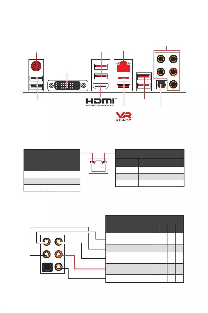
8Задняя панель портов ввода/ вывода
Конфигурация портов Аудио
Порты Аудио Канал
2468
Выход центральной
колонки/ сабвуфера ● ●
Тыловые колонки ● ● ●
Линейный вход/ Выход
боковых колонок ●
Линейный выход/ Выход
фронтальных колонок ●●●●
Микрофонный вход
(●: подключен, Пусто: не подключен)
Задняя панель портов ввода/ вывода
Подключение/ Работа
индикатора
Состояние Описание
Выкл.Не подключен
Желтый Подключен
Мигает Передача данных
Скорость передачи данных
Состояние Описание
Выкл. 10 Мбит/с подключение
Зеленый 100 Мбит/с подключение
Оранжевый 1 Гбит/с подключение
Таблица состояний индикатора порта LAN
LAN
USB 2.0
PS/2
Порты Аудио
Оптический
S/PDIF-Out
USB 3.2 Gen1
USB 3.2 Gen1
USB 3.2 Gen2
DVI-D
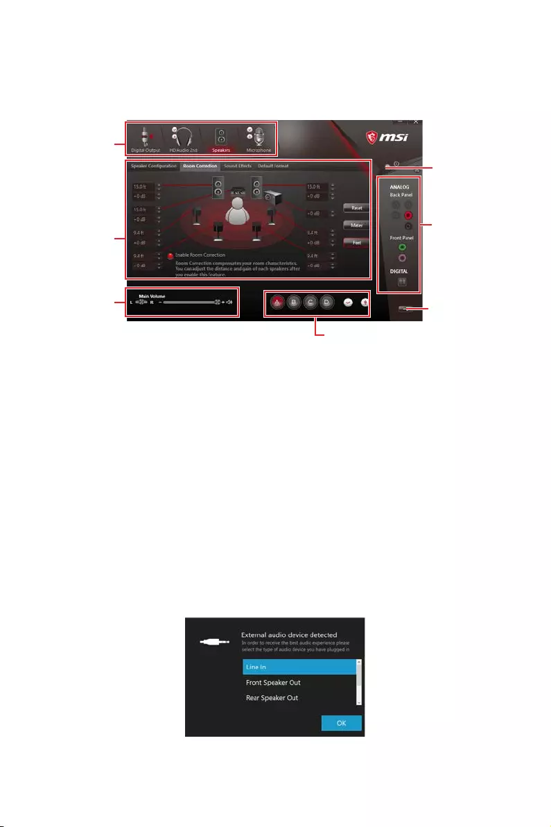
9
Задняя панель портов ввода/ вывода
Менеджер Realtek HD Audio
После установки драйвера Realtek HD Audio, в системном трее появится
значок Realtek HD Audio Manager. Дважды щелкните по значку для запуска
приложения.
yВыбор устройства — позволяет выбрать источник аудио выхода и изменить
соответствующие параметры. Отмеченное устройство будет использоваться
по умолчанию.
yДополнительные эффекты — это список опций по настройке звуковых
эффектов для входного и выходного сигнала аудио устройства.
yМастер—громкость — регулирует громкость или баланс правой и левой
колонок, подключенных к передней или задней панели.
yПрофили — позволяют переключаться между различными профилями.
yРасширенные настройки — обеспечивают работу с двумя независимыми
потоками аудио.
yСостояние разъемов — отображает все устройства воспроизведения и
записи, подключенные к компьютеру.
yНастройки подключений — настраивают параметры подключения.
Автоматическое всплывающее диалоговое окно
При подключении устройства к разъему аудио появится диалоговое окно с
просьбой подтвердить подключенное устройство.
Каждый разъем соответствует его настройкам по умолчанию, как показано
на следующей странице.
Состояние
разъемов
Выбор
устройства
Настройки
подключений
Профили
Мастер—
громкость
Дополнительные
эффекты
Расширенные
настройки

10 Задняя панель портов ввода/ вывода
AUDIO INPUT
Rear Front
Side Center/
Subwoofer
Подключение наушников и микрофона
Подключение внешнего стерео усилителя (колонок)
Подключение звуковой системы 7.1
AUDIO INPUT
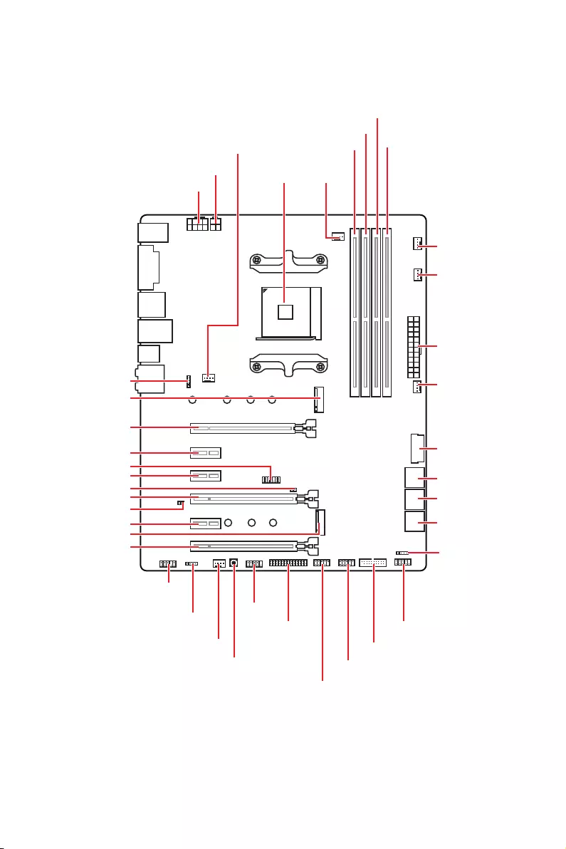
11
Компоненты материнской платы
Компоненты материнской платы
SATA▼3▲4
SATA▼1▲2
SATA▼5▲6
CPU_FAN1
JRGB1
JRGB2
PUMP_FAN1
PCI_E1
PCI_E2
PCI_E3
PCI_E4
PCI_E5
PCI_E6
JTPM1
Процессорный
сокет
CPU_PWR1
CPU_PWR2
JBAT1
M2_2
M2_1
DIMMA1
SYS_FAN1
DIMMA2
DIMMB1
DIMMB2
JLPT1
JUSB1
JUSB2
JFP2
JFP1
JAUD1
ATX_PWR1
SYS_FAN3
SYS_FAN4
SYS_FAN2
Clear CMOS
JCOM1
JUSB4
JCI1
JUSB3
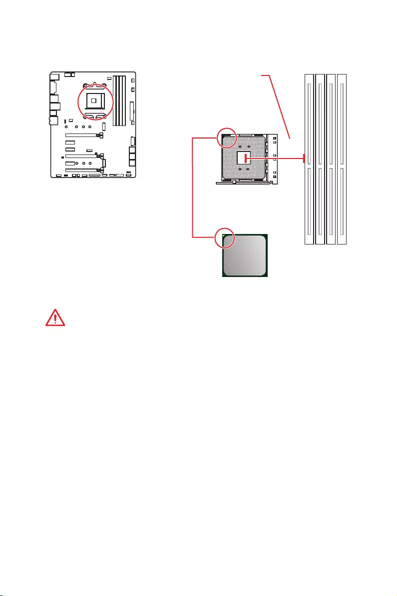
12 Компоненты материнской платы
Процессорный сокет
Процессор AM4
На поверхности процессора AM4
имеется золотой треугольник
для правильной установки
процессора относительно
процессорного сокета
материнской платы. Золотой
треугольник указывает на
контакт 1.
Внимание!
y
Из—за особенностей архитектуры процессоров АМ4, замена процессора
может привести к сбросу настроек BIOS до значений по умолчанию.
y
Перед установкой или заменой процессора, необходимо отключить кабель
питания.
y
При установке процессора обязательно установите процессорный
кулер. Кулер, представляющий собой систему охлаждения процессора,
предотвращает перегрев и обеспечивает стабильную работу системы.
y
Перед включением системы проверьте герметичность соединения между
процессором и радиатором.
y
Перегрев может привести к серьезному повреждению процессора и
материнской платы. Всегда проверяйте работоспособность вентилятора для
защиты процессора от перегрева. При установке кулера нанесите ровный
слой термопасты (или термоленту) на крышку установленного процессора
для улучшения теплопередачи.
y
Если вы приобрели отдельно процессор и процессорный кулер, подробное
описание установки см. в документации в данному кулеру.
y
Данная системная плата разработана с учетом возможности ее
«разгона». Перед выполнением разгона системы убедитесь в том, что все
компоненты системы смогут его выдержать. Производитель не рекомендует
использовать параметры, выходящие за пределы технических характеристик
устройств. Гарантия MSI
®
не распространяется на повреждения и другие
возможные последствия ненадлежащей эксплуатации оборудования.
53.43
мм
Расстояние от центра
процессора до ближайшего
слота DIMM.

13
Компоненты материнской платы
Слоты DIMM
Внимание!
y
Всегда устанавливайте модуль памяти сначала в слот DIMMA2.
y
В связи со спецификой использования ресурсов чипсета, доступный объем
памяти будет немного меньше, чем фактически установленный.
y
На основе характеристик процессора, рекомендуется устанавливать
напряжение на памяти DIMM менее 1.35 В. Это позволит защитить
процессор.
y
Некоторые модули памяти при разгоне могут работать на частотах ниже
заявленной производителем, поскольку выставляемая для памяти частота
зависит от информации, записанной в SPD (Serial Presence Detect). Зайдите в
BIOS и выберите опцию DRAM Frequency, чтобы установить заявленную или
более высокую частоту.
y
При установке памяти во все слоты, а также при ее разгоне, рекомендуется
использовать более эффективную систему охлаждения памяти.
y
Совместимость и стабильность работы установленного модуля памяти при
разгоне зависит от установленного процессора и других устройств.
y
Из—за ограничений официальной спецификации процессора АМ4/
контроллера памяти, модули памяти могут работать на частотах
ниже заявленной производителем при насройках по умолчанию.
Дополнительную информацию о совместимых модулях памяти можно найти
на веб—сайте www.msi.com.
DIMMA1 DIMMB1
Канал A Канал B
DIMMA2 DIMMB2
Рекомендации по установке модулей памяти
DIMMB2 DIMMB2
DIMMB1
DIMMA2 DIMMA2 DIMMA2
DIMMA1
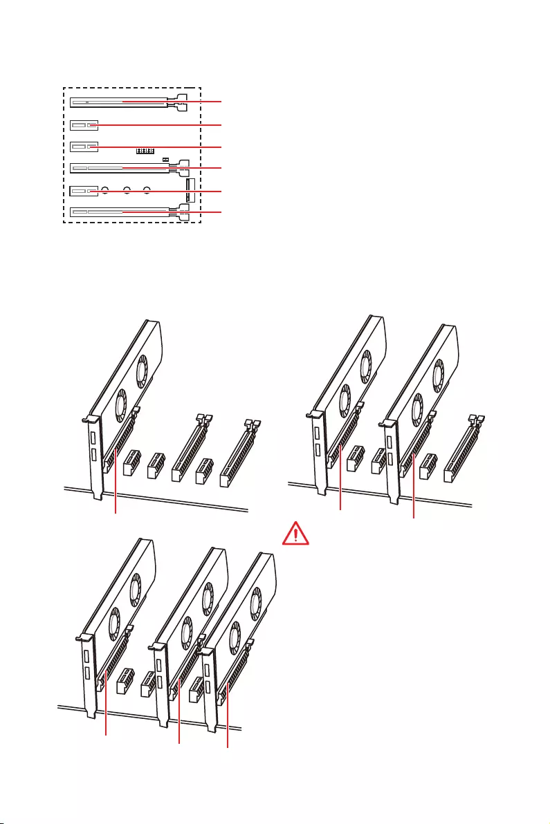
14 Компоненты материнской платы
Рекомендации по установке нескольких видеокарт (для
процессоров серии RYZEN™)
x16 x8
x8
x8
x8 x4
Внимание!
y
При установке массивной видеокарты,
необходимо использовать такой
инструмент, как MSI Gaming Series
Graphics Card Bolster для поддержки
веса графической карты и во избежание
деформации слота.
y
Для установки одной карты
расширения PCIe x16 с оптимальной
производительностью рекомендуется
использовать слот PCI_E1.
y
Перед установкой или извлечением
плат расширения убедитесь, что кабель
питания отключен от электрической
сети. Прочтите документацию на карту
расширения и выполните необходимые
дополнительные аппаратные или
программные изменения для данной
карты.
PCI_E4: PCIe 3.0 x8*/ Недоступно**/ Недоступно***
PCI_E1~6: Слоты расширения PCIe
PCI_E2: PCIe 2.0 x1
PCI_E3: PCIe 2.0 x1
PCI_E5: PCIe 2.0 x1
PCI_E6: PCIe 2.0 x4
PCI_E1: PCIe 3.0 x16*/ PCIe 3.0 x8**/ PCIe 3.0 x4***
* Для процессоров AMD Ryzen™ 1-го, 2-го и 3-го поколения
** Для процессоров Ryzen™ с видеокартой Radeon™ Vega и процессоров AMD
Ryzen™ 2-го поколения с видеокартой Radeon™
*** Для процессоров Athlon™ с видеокартой Radeon™ Vega

15
Компоненты материнской платы
Таблица пропускной способности PCIe
Для процессоров AMD Ryzen™ 1-го, 2-го и 3-го поколения
Слот Одинарный 2-Way
PCI_E1 (CPU) Gen 3.0 x 16* Gen 3.0 x 8*
PCI_E2 (PCH) Gen 2.0 x 1 Gen 2.0 x 1
PCI_E3 (PCH) Gen 2.0 x 1 Gen 2.0 x 1
PCI_E4 (CPU) ─Gen 3.0 x 8*
PCI_E5 (PCH) Gen 2.0 x 1 Gen 2.0 x 1
PCI_E6 (PCH) Gen 2.0 x 4 ─Gen 2.0 x 4 ─
M2_1 (CPU) Gen 3.0 x 4 Gen 3.0 x 4
M2_2 (PCH) ─Gen 2.0 x 4 ─Gen 2.0 x 4
(─: недоступно, *: видеокарта)
Для процессоров Ryzen™ с видеокартой Radeon™ Vega и процессоров AMD
Ryzen™ 2-го поколения с видеокартой Radeon™
Слот Одинарный
PCI_E1 (CPU) Gen 3.0 x 8*
PCI_E2 (PCH) Gen 2.0 x 1
PCI_E3 (PCH) Gen 2.0 x 1
PCI_E4 (CPU) ─
PCI_E5 (PCH) Gen 2.0 x 1
PCI_E6 (PCH) Gen 2.0 x 4 ─
M2_1 (CPU) Gen 3.0 x 4
M2_2 (PCH) ─Gen 2.0 x 4
(─: недоступно, *: видеокарта)
Для процессоров Athlon™ с видеокартой Radeon™ Vega
Слот Одинарный
PCI_E1 (CPU) Gen 3.0 x 4*
PCI_E2 (PCH) Gen 2.0 x 1
PCI_E3 (PCH) Gen 2.0 x 1
PCI_E4 (CPU) ─
PCI_E5 (PCH) Gen 2.0 x 1
PCI_E6 (PCH) Gen 2.0 x 4 ─
M2_1 (CPU) Gen 3.0 x 2
M2_2 (PCH) ─Gen 2.0 x 4
(─: недоступно, *: видеокарта)
Внимание!
Слот PCI_E6 будет недоступен при установке PCIe M.2 SSD в разъеме M2_2.

16 Компоненты материнской платы
M2_1~2: Разъем M.2 (Ключ M)
Видео Инструкция
Смотрите видео, чтобы узнать как установить M.2 SSD.
http://youtu.be/JCTFABytrYA
Установка M.2 SSD
30°
2. Закрутите стойку
для крепления M.2
модуля в подходящее
отверстие, в
соответствии с длиной
вашего M.2 SSD.
3. Вставьте M.2 SSD в
разъем М.2 под углом
30 градусов.
4. Закрепите M.2
SSD с помощью
прилагаемого винта
для M.2.
1. Выкрутите стойку
для крепления
M.2 модуля из
материнской платы.
Прилагаемый винт
для M.2
Внимание!
y
Порт SATA1 будет недоступен при установке SATA
M.2 SSD в разъеме M2_2.
y
Слот PCI_E6 будет недоступен при установке PCIe
M.2 SSD в разъеме M2_2.
y
Разъем M2_1 только поддерживает режим PCIe.
M2_1
M2_2

17
Компоненты материнской платы
SATA1~6: Разъемы SATA 6Гб/с
Эти разъемы представляют собой интерфейсные порты SATA 6Гб/с. К
каждому порту можно подключить одно устройство SATA.
SATA5
SATA3
SATA1
SATA6
SATA4
SATA2
Внимание!
y
Порт SATA1 будет недоступен при установке SATA M.2 SSD в разъеме M2_2.
y
Избегайте перегибов кабеля SATA под прямым углом. В противном случае,
возможна потеря данных при передаче.
y
Кабели SATA оснащены одинаковыми коннекторами с обеих сторон.
Однако, для экономии занимаемого пространства к материнской плате
рекомендуется подключать плоский разъем.
1
2 26
25
1 RSTB# 2 AFD# 3 PRND0
4 ERR# 5 PRND1 6 PINIT#
7 PRND2 8 LPT_SLIN# 9 PRND3
10 Ground 11 PRND4 12 Ground
13 PRND5 14 Ground 15 PRND6
16 Ground 17 PRND7 18 Ground
19 ACK# 20 Ground 21 BUSY
22 Ground 23 PE 24 Ground
25 SLCT 26 No Pin
JLPT1: Разъем параллельного порта
Данный разъем позволяет подключить параллельный порт, размещенный
на внешнем бракете.
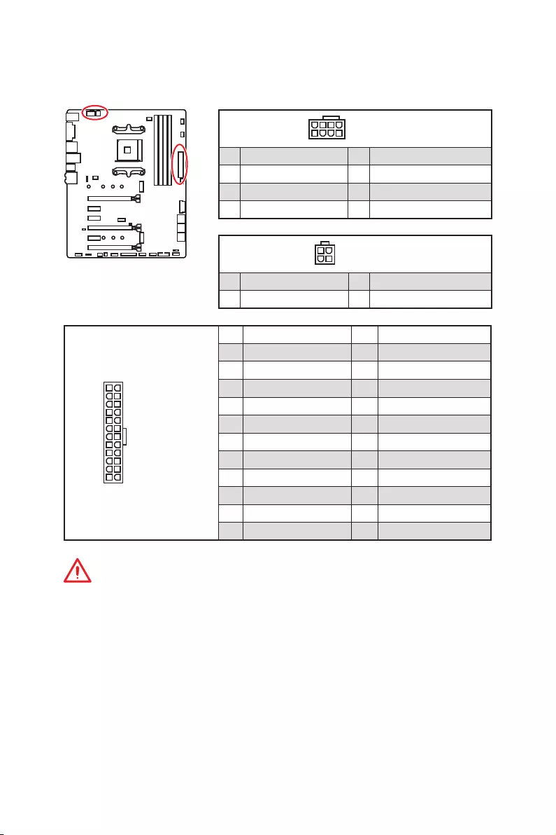
18 Компоненты материнской платы
24
131
12
ATX_PWR1
1 +3.3V 13 +3.3V
2 +3.3V 14 -12V
3 Ground 15 Ground
4 +5V 16 PS-ON#
5 Ground 17 Ground
6 +5V 18 Ground
7 Ground 19 Ground
8 PWR OK 20 Res
9 5VSB 21 +5V
10 +12V 22 +5V
11 +12V 23 +5V
12 +3.3V 24 Ground
5
4 1
8CPU_PWR1
1 Ground 5 +12V
2 Ground 6 +12V
3 Ground 7 +12V
4 Ground 8 +12V
Внимание!
Для обеспечения стабильной работы системной платы проверьте
надежность подключения всех кабелей питания к блоку питания АТХ.
CPU_PWR1, CPU_PWR2, ATX_PWR1: Разъемы питания
Данные разъемы предназначены для подключения блока питания ATX.
3
2 1
4CPU_PWR2
1 Ground 3 +12V
2 Ground 4 +12V
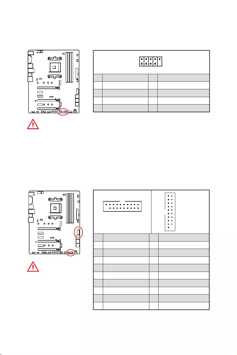
19
Компоненты материнской платы
JUSB3~4: Разъемы USB 3.2 Gen1
Данные разъемы предназначены для подключения портов USB 3.2 Gen1 на
передней панели.
Внимание!
Помните, что во
избежание повреждений,
необходимо правильно
подключать контакты
питания и земли.
1 10
1120
JUSB3
1
10 11
20
JUSB4
1Power 11 USB2.0+
2 USB3_RX_DN 12 USB2.0-
3 USB3_RX_DP 13 Ground
4 Ground 14 USB3_TX_C_DP
5 USB3_TX_C_DN 15 USB3_TX_C_DN
6 USB3_TX_C_DP 16 Ground
7 Ground 17 USB3_RX_DP
8 USB2.0- 18 USB3_RX_DN
9 USB2.0+ 19 Power
10 NC 20 No Pin
JUSB1~2: Разъемы USB 2.0
Данные разъемы предназначены для подключения портов USB 2.0 на
передней панели.
1
2 10
9
1VCC 2VCC
3 USB0- 4 USB1-
5 USB0+ 6 USB1+
7 Ground 8 Ground
9 No Pin 10 NC
Внимание!
y
Помните, что во избежание повреждений, необходимо правильно
подключать контакты VCC и земли.
y
Для того, чтобы зарядить ваш iPad, iPhone и iPod через порты USB,
пожалуйста, установите утилиту MSI
®
SUPER CHARGER.
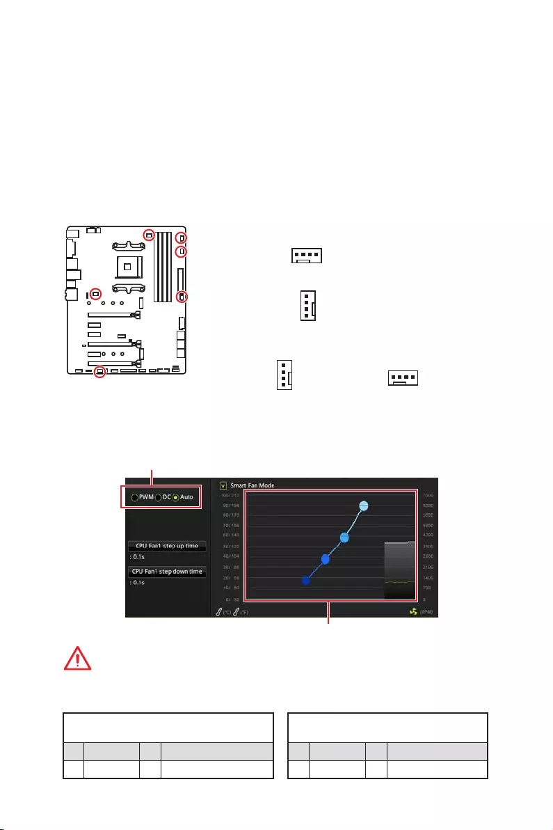
20 Компоненты материнской платы
CPU_FAN1, PUMP_FAN1, SYS_FAN1~4: Разъемы вентиляторов
Разъемы вентиляторов можно разделить на два типа: с PWM (PulseWidth
Modulation) управлением и управлением постоянным током. Разъемы
вентиляторов с PWM управлением имеют контакт с постоянным напряжением
12В, а также контакт с сигналом управления скоростью вращения.
Управление скоростью вращения вентиляторов с управлением постоянным
током, осуществляется через соответсвующие разъемы путем изменения
величины напряжения. Поэтому, при подключении 3-х контактного (Non-
PWM) вентилятора к разъему для вентилятора PWM, скорость вентилятора
всегда будет максимальной. Работа такого вентилятора может оказаться
достаточно шумной. CPU_FAN1 и PUMP_FAN1 могут автоматически определить
режим работы вентилятора — PWM или DC. Для настройки режима работы
вентилятора вручную (PWM или DC), следуйте указаниям ниже.
Назначение контактов разъема для режима
PWM
1 Ground 2 +12V
3 Sense 4 Speed Control Signal
Назначение контактов разъема для
режима DC
1 Ground 2 Voltage Control
3 Sense 4 NC
Разъем вентилятора с PWM управлением по
умолчанию
Разъем вентилятора с управлением
постоянным током по умолчанию
Переключение режимов работы и скорости вращения вентилятора
В меню BIOS > HARDWARE MONITOR вы можете выбрать режим работы
вентилятора: PWM или DC и настроить его скорость вращения.
Выберите режим PWM, DC или Auto
Внимание!
Убедитесь, что вентиляторы работают правильно после выбора режима PWM/ DC.
Вы можете регулировать скорость вращения вентилятора
в зависимости от температуры процессора путем
изменения положения градиентных точек.
1
SYS_FAN1/ SYS_FAN3/ SYS_FAN4
1
SYS_FAN2
1
CPU_FAN1
Назначение контактов разъема для подключения вентилятора
Разъем вентилятора с автоматическим
управлением по умолчанию
1
PUMP_FAN1
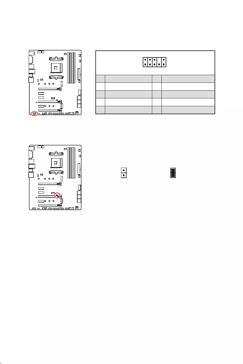
21
Компоненты материнской платы
JAUD1: Разъем аудио передней панели
Данный разъем предназначен для подключения аудиоразъемов передней
панели.
1
2 10
9
1 MIC L 2 Ground
3 MIC R 4 NC
5 Head Phone R 6 MIC Detection
7 SENSE_SEND 8 No Pin
9 Head Phone L 10 Head Phone Detection
JCI1: Разъем датчика открытия корпуса
К этому разъему подключается кабель от датчика открытия корпуса.
Нормально
(По умолчанию)
Разрешить запись
по событию
открытия корпуса
Использование датчика открытия корпуса
1. Подключите датчик открытия корпуса к разъему JCI1.
2. Закройте крышку корпуса.
3. Войдите в BIOS > Settings > Security > Chassis Intrusion Configuration.
4. Установите Chassis Intrusion в Enabled.
5. Нажмите клавишу F10, чтобы сохранить настройки и выйти, а затем
нажмите клавишу Enter, чтобы выбрать Yes.
6. При открытии корпуса на экране будет появляться предупреждающее
сообщение каждый раз при включении компьютера.
Сброс сообщения об открытии корпуса
1. Войдите в BIOS > Settings > Security > Chassis Intrusion Configuration.
2. Выберите Chassis Intrusion, Reset.
3. Нажмите клавишу F10, чтобы сохранить настройки и выйти, а затем
нажмите клавишу Enter, чтобы выбрать Yes.
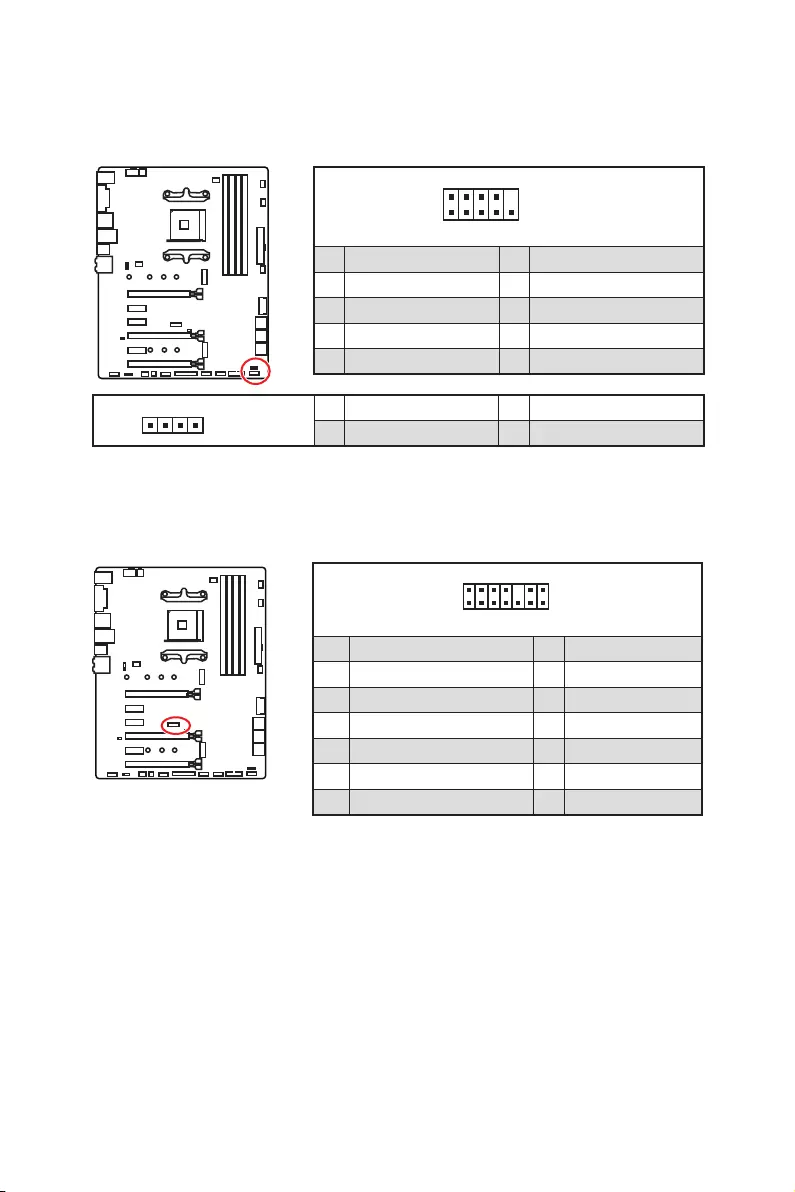
22 Компоненты материнской платы
1
2 14
13
1 LPC Clock 2 3V Standby power
3 LPC Reset 4 3.3V Power
5 LPC address & data pin0 6 Serial IRQ
7 LPC address & data pin1 8 5V Power
9 LPC address & data pin2 10 No Pin
11 LPC address & data pin3 12 Ground
13 LPC Frame 14 Ground
JTPM1: Разъем модуля TPM
Данный разъем используется для подключения модуля ТРМ (Trusted Platform
Module). Дополнительные сведения см. в описании модуля ТРМ.
JFP1, JFP2: Разъемы передней панели
Эти разъемы служат для подключения кнопок и светодиодных индикаторов,
расположенных на передней панели.
1
2 10
9
JFP1
1 HDD LED + 2 Power LED +
3 HDD LED — 4 Power LED —
5 Reset Switch 6 Power Switch
7 Reset Switch 8 Power Switch
9 Reserved 10 No Pin
1
JFP2
1 Speaker — 2 Buzzer +
3 Buzzer — 4 Speaker +

23
Компоненты материнской платы
JRGB1, JRGB2: Разъем RGB LED
Разъем JRGB1/JRGB2 предназначен для подключения светодиодных лент
5050 RGB 12В и кулера процессора AMD с RGB светодионой подсветкой.
Внимание!
y
Разъем JRGB1/JRGB2 поддерживает подключение 5050 RGB светодиодных
лент (12В/G/R/B) с мощностью 3А (12В).
y
Обратите внимание, что длина лент должна быть не более 2 метров, иначе
яркость свечения будет падать.
y
Перед установкой или заменой светодиодных лент RGB, необходимо
полностью обесточить систему и отключить кабель питания.
y
Используйте утилиту MSI
®
для управления удлинительными
светодиодными лентами.
1
JRGB1/
JRGB2
JRGB1
JRGB2
Удлинительный
кабель
5050 RGB LED ленты 12В
1
JRGB1
JRGB2
1 +12V 2 G
3 R 4 B
1
2 10
9
1 DCD 2 SIN
3 SOUT 4 DTR
5 Ground 6 DSR
7 RTS 8 CTS
9 RI 10 No Pin
JCOM1: Разъем последовательного порта
Данный разъем позволяет подключить последовательный порт,
размещенный на внешнем бракете.
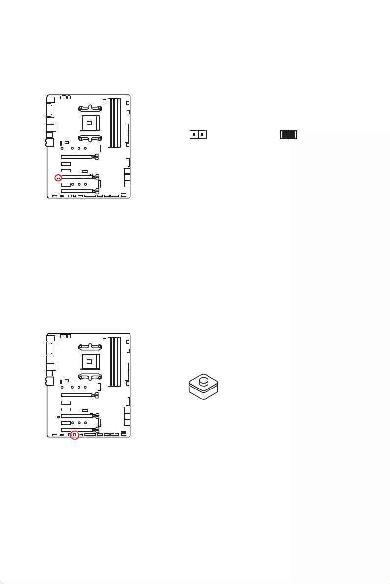
24 Компоненты материнской платы
JBAT1: Джампер очистки данных CMOS (Сброс BIOS)
На плате установлена CMOS память с питанием от батарейки для хранения
данных о конфигурации системы. Для сброса конфигурации системы
(очистки данных CMOS памяти), воспользуйтесь этим джампером.
Сохранение данных
(По умолчанию)Очистка данных/
Сброс BIOS
Сброс настроек BIOS до значений по умолчанию
1. Выключите компьютер и отключите шнур питания.
2. Используйте джампер, чтобы замкнуть соответствующие контакты JBAT1
в течение 5-10 секунд.
3. Снимите джампер с контактов JBAT1.
4. Подключите шнур питания и включите компьютер.
CLR_CMOS1: Кнопка очистки данных CMOS
Выключите компьютер. Нажмите и удерживайте кнопку очистки данных
CMOS на 5-10 секунд для сброса настройки BIOS по умолчанию.
Кнопка очистки
данных CMOS

25
Настройка BIOS
Настройка BIOS
Настройки по умолчанию обеспечивают оптимальную производительность
и стабильность системы при нормальных условиях. Если вы недостаточно
хорошо знакомы с BIOS, всегда устанавливайте настройки по умолчанию.
Это позволит избежать возможных повреждений системы, а также проблем
с загрузкой.
Внимание!
y
С целью улучшения производительности, меню BIOS постоянно
обновляется. В связи с этим данное описание может немного отличаться
от последней версии BIOS и может использоваться в качестве справки. Для
описания какого либо пункта меню настроек BIOS, вы можете обратиться к
информационной панели HELP.
y
Изображения в этой главе приведены исключительно в справочных целях
и могут отличаться от фактических.
Вход в настройки BIOS
Нажмите клавишу Delete, когда появляется сообщение на экране Press DEL
key to enter Setup Menu, F11 to enter Boot Menu во время загрузки.
Функциональные клавиши
F1: Общая справка
F2: Добавить / Удалить избранный предмет
F3: Вход в меню Избранное
F4: Вход в меню технических параметров процессора
F5: Вход в меню Memory-Z
F6: Загрузить оптимизированные настройки по умолчанию
F7: Переключить между расширенном режимом и режимом EZ
F8: Загрузить профиль разгона
F9: Сохранить профиль разгона
F10: Сохранение изменений и перезагрузка*
F12: Сделать скриншот и сохранить его на USB флэш—диск (только FAT /
FAT32 формат).
Ctrl+F: Вход в страницу поиска
* При нажатии клавиши F10 появится информационное окно. Выберите Yes
или No, чтобы подтвердить выбор.

26 Настройка BIOS
Сброс BIOS
В некоторых ситуациях необходиимо выполнить восстановление настроек
BIOS до значений по умолчанию. Существует несколько способов сброса
настроек:
yВойдите в BIOS и нажмите клавишу F6 для загрузки оптимизированных
значений по умолчанию.
yЗамкните джампер Clear CMOS на материнской плате.
Внимание!
Убедитесь, что компьютер выключен перед очисткой данных CMOS.
Для получения дополнительной информации о сбросе настроек BIOS,
обратитесь к разделу “Джампер очистки данных CMOS”.
Обновление BIOS
Обновление BIOS при помощи M-FLASH
Подготовительные операции:
Пожалуйста, скачайте последнюю версию файла BIOS с сайта MSI, который
соответствует вашей модели материнской платы. Сохраните файл BIOS на
флэш—диске USB.
Обновление BIOS:
1. Вставьте флэш—диск USB, содержащий файл обновления в компьютер.
2. Нажмите клавиши <Ctrl+F5> во время процедуры POST.
3. Нажмите на кнопку Yes для перезагрузки системы и входа в режим
обновления.
4. Выберите файл BIOS для выполнения процесса обновления BIOS.
5. После завершения процесса обновления, система перезагрузится
автоматически.
Обновление BIOS при помощи Live Update 6
Перед обновлением:
Убедитесь, что драйвер локальной сети установлен и есть подключение к
сети Интернет.
Обновление BIOS:
1. Установите и запустите MSI LIVE UPDATE 6.
2. Выберите BIOS Update.
3. Нажмите на кнопку Scan.
4. Нажмите на значок Download,
чтобы загрузить и установить последнюю
версию файла BIOS.
5. Нажмите кнопку Next и выберите In Windows mode. И затем нажмите
кнопку Next и Start для запуска обновления BIOS.
6. По завершению процесса обновления, система перезагрузится
автоматически.
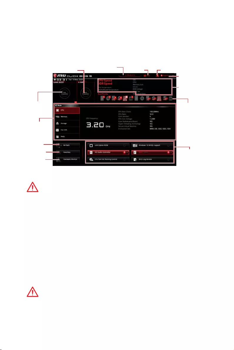
27
Настройка BIOS
Режим EZ
Режим EZ предоставляет основную информацию о системе и позволяет
выполнить основные операции по настройке. Для настройки расширенных
функций BIOS, пожалуйста, войдите в Расширенный режим, путем нажатия
Переключатель режимов установки или при помощи функциональной
клавиши F7.
Экран
просмотра
информации
Информация
о системе
Приоритет
загрузочных
устройств
Функциональные
клавиши
Язык
Поиск
Скриншот
Переключатель
режимов установки
M-Flash
Избранное
Аппаратный
мониторинг
Переключатель
GAME BOOST
Переключатель A-XMP
yПереключатель GAME BOOST — щелкните для переключения GAME BOOST в
ОС.
Внимание!
Для сохранения оптимальной производительность и стабильности системы
после активации функции GAME BOOST, пожалуйста, не делайте никаких
изменений в меню OC и не загружайте настройки по умолчанию.
yПереключатель A-XMP (опционально) — нажмите на внутренний
значок, чтобы включить/ выключить A-XMP. Для выбора профиля памяти
переключите внешний значок. Этот переключатель доступен только в
случае, если установлен модуль памяти с подержкой данной функции.
yПереключатель режимов установки — нажмите эту вкладку или клавишу
F7, чтобы переключиться между режимами EZ и разгона.
yСкриншот — нажмите на эту вкладку или клавишу F12, чтобы сделать
скриншот и сохранить его на флэш—диск USB (только FAT/ FAT32).
yПоиск — кликните по данной вкладке или нажмите клавиши Ctrl + F для
перехода на страницу поиска. Это позволяет выполнить поиск по имени
параметра BIOS. Для вывода списка пунктов BIOS, введите имя параметра.
Наведите указатель мыши на пустое место и щелкните правой кнопкой
мыши, для выхода со страницы поиска.
Внимание!
На странице поиска доступны только функциональные клавиши F6, F10 и
F12.
yЯзык — позволяет выбрать язык интерфейса для настройки BIOS.

28 Настройка BIOS
yИнформация о системе — показывает частоту процессора/ памяти,
температуру процессора/ материнской платы, информацию о материнской
плате/процессоре, размер памяти, напряжение на процессоре/ памяти,
версию BIOS и дату создания.
yПриоритет загрузочных устройств — вы можете переместить инонку
устройства для изменения приоритета загрузки. Приоритет загрузки
устанавливается слева направо, от высокого к низкому.
yЭкран просмотра информации — нажмите на кнопку CPU, Memory, Storage,
Fan Info и Help в левой части экрана для отображения соответствующей
информации.
yФункциональные клавиши — включают или выключают LAN Option ROM,
HD audio controller, Window 10 WHQL Support, AHCI, RAID, CPU Fan Fail Warning
Control и BIOS Log Review, при нажатии на соответствующую кнопку.
Внимание!
y
В процессе установки Windows может потребоваться драйвер RAID. Вы
можете найти драйвер на диске MSI с драйверами из комплекта поставки.
y
Вы также можете использовать MSI SMART TOOL для создания установочного
диска Windows
®
, который будет включать драйвер RAID.
y
В случае удаления созданного ранее RAID массива через настройки UEFI
BIOS, ваша система не сможет быть загружена.
yM-Flash — нажмите на эту кнопку для отображения меню M-Flash. Пункт
позволяет выбрать способ обновления BIOS при помощи USB флеш
накопителя.
yАппаратный мониторинг — нажмите на эту кнопку для отображения
меню аппаратного мониторинга. Пункт позволяет вручную регулировать
скорость вращения вентиляторов в процентах.
yИзбранное — нажмите на данную кнопку или клавишу F3 для входа в меню
Избранное. Позволяет создать личное меню BIOS, где вы можете сохранить
и получить доступ к вашим любимым и часто используемым настройкам
BIOS.
Главная страница по умолчанию — позволяет выбрать меню BIOS
(например, параметры, OC…, и т.д.) в качестве главной страницы BIOS.
Избранное1~5 — позволяет добавлять наиболее часто используемые /
любимые пункты настройки BIOS на одну страницу.
Добавление пункта BIOS в страницу Избранное (избранное 1~5)
1. Выберите пункт BIOS в настройках OC или меню OC.
2. Щелкните правой кнопкой мыши или нажмите клавишу F2.
3. Выберите любимую страницу и нажмите на кнопку OK.
Удаление пункта BIOS из страницы Избранное
1. Выберите пункт BIOS на странице Избранное (избранное 1~5).
2. Щелкните правой кнопкой мыши или нажмите клавишу F2.
3. Выберите Delete и нажмите на кнопку OK.
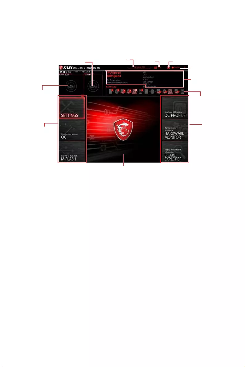
29
Настройка BIOS
Режим разгона
Нажмите переключатель режимов установки или функциональную
клавишу F7 для переключения между режимами EZ и разгона в настройках
BIOS.
Переключатель A-XMP
Переключатель
GAME BOOST
Информация
о системе
Приоритет
загрузочных
устройств
Выбор меню
BIOS
Язык
ПоискСкриншот
Переключатель
режимов установки
Экран меню
Выбор меню
BIOS
yПереключатель GAME BOOST/ Переключатель режимов установки/
Скриншот/ Изобранное/ Язык/ Информация о системе/ Приоритет
загрузочных устройств — пожалуйста, обратитесь к разделу Режим EZ.
yВыбор меню BIOS — доступны следующие опции:
SETTINGS — в данном меню представлены настройки чипсета и
загрузочных устройств.
OC — позволяют регулировать частоту и напряжение. Увеличение
частоты приводит к увеличению производительности.
M-FLASH — позволяет выбрать метод обновления BIOS с USB флэш—диска.
OC PROFILE — позволяет управлять профилями разгона.
HARDWARE MONITOR — позволяет установить скорость работы
вентиляторов и мониторинг напряжений системы.
BOARD EXPLORER — предоставляет информации об установленных
устройствах на материнской плате.
yЭкран меню — отображаются настройки BIOS и дополнительная
информация.
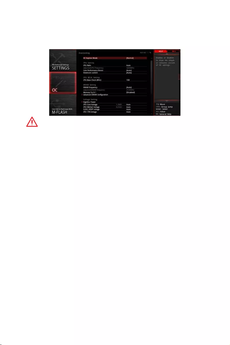
30 Настройка BIOS
Меню OC
Данное меню предназначено для опытных пользователей и предоставляет
возможности для «разгона» системы.
Внимание!
y
Разгонять ПК вручную рекомендуется только опытным пользователям.
y
Производитель не гарантирует успешность разгона. Неправильное
выполнение разгона может привести к аннулированию гарантии и
серьезному повреждению оборудования.
y
Неопытным пользователям рекомендуется использовать функцию GAME
BOOST.
y
Пункты BIOS в меню OC будут меняться в зависимости от моделя
процессора.
fOC Explore Mode [Normal]
Включение или выключение отображения нормального или экспертного
режима настроек разгона.
[Normal] Стандартные параметры разгона в BIOS.
[Expert] Расширенные параметры разгона в BIOS для опытных
пользователей.
Примечание: Символом * отмечаются параметры разгона в режиме Expert.
fCPU Ratio [Auto]
Задание множителя процессора для установки его тактовой частоты. Этот
пункт появляется при установке процессора с поддержкой данной функции.
fCore Performance Boost [Auto]
Включение или выключение Core Performance Boost (CPB). Этот пункт
появляется при установке процессора с поддержкой данной функции.
fDowncore Control [Auto] (опционально)
Задание количество используемых ядер процессора. Этот пункт появляется
при установке процессора с поддержкой данной функции.
fA-XMP [Disabled]
Включите A-XMP или выберите профиль модуля памяти для разгона. Данный
пункт доступен, когда установлен модуль памяти, процессора и материнской
платы с поддержкой данной функции.

31
Настройка BIOS
fDRAM Frequency [Auto]
Установка частоты памяти DRAM. Обратите внимание, что возможность
успешного разгона не гарантируется.
fMemory Try It ! [Disabled]
Позволяет улучшить совместимость памяти и производительность, путем
выбора наиболее оптимального пресета.
fMemory Retry Count [5]
Устанавливает количество попыток разгона памяти. При неудачном разгоне,
установка значения данного пункта в [5], позволяет перезагрузить систему
5 раз в той же разогнанной конфигурации. При неудачной попытке разгона,
параметры системы будут восстановлены по умолчанию.
fAdvanced DRAM Configuration (опционально)
Нажмите Enter для входа в подменю. Пользователь может настроить
тайминги для каждого канала памяти. Система может работать нестабильно
или не загружаться после изменения тамингов памяти. Если система
работает нестабильно, пожалуйста, очистите данные CMOS и восстановите
настройки по умолчанию. (см. перемычка очистки данных CMOS/раздел
кнопки для очистки данных CMOS и вход в BIOS, чтобы загрузить настройки
по умолчанию.)
fDigitALL Power
Нажмите Enter для входа в подменю. Функция управляет цепями питания,
связанными с PWM процессора.
fCPU Loadline Calibration Control [Auto]
Напряжение на процессоре уменьшается пропорционально, в
зависимости от его загрузки. Повышение значения Load-line Calibration
приводит к повышению напряжения и производительности при разгоне,
но и увеличивает температуру процессора и VRM. При установке в Auto,
BIOS установит данный параметр автоматически.
fCPU Over Voltage Protection [Auto]
Устанавливает верхнюю границу максимального напряжения для защиты
процессора от повышенного напряжения. Если установлено Auto, BIOS
автоматически настроит этот параметр. Чем выше значение, тем ниже
степень защиты и выше вероятность выхода системы из строя.
fCPU Under Voltage Protection [Auto]
Устанавливает нижнюю границу напряжения для защиты процессора от
пониженного напряжения. Если установлено Auto, BIOS автоматически
настроит этот параметр. Чем выше значение, тем ниже степень защиты и
выше вероятность выхода системы из строя.
fCPU Over Current Protection [Auto]
Устанавливает ограничение по максимальному току для защиты
процессора. При устанвке в Auto, BIOS автоматически настроит этот
параметр.
[Auto] Этот параметр будет настроен автоматически с помощью
BIOS.
[Enhanced] Расширяет ограничение по току от перегрузки по току.

32 Настройка BIOS
fCPU Switching Frequency [Auto]
Устанавливает скорость работы PWM для стабилизации напряжения ядра
процессора и минимизации диапазона пульсаций. Увеличение рабочей
частоты PWM приводит к сильному нагреву MOSFET. Перед тем как
увеличить значение убедитесь, что охлаждение для MOSFET установлено.
При установке в Auto, BIOS автоматически настроит этот параметр.
fCPU VRM Over Temperature Protection [Auto]
Устанавливает верхнее значение температуры на CPU VRM для защиты
от перегрева. Частота CPU может быть регулируются, когда CPU VRM
над заданной температуры. При установке в Auto, BIOS настроит этот
параметр.
fCPU Power Duty Control [Thermal Balance]
Установка максимального тока для каждой фазы и температурного
режима работы для каждого компонента VRM.
[Thermal Balance] Поддерживает тепловой баланс VRM.
[Current Balance] Поддерживает токовый баланс VRM.
fCPU NB Loadline Calibration Control [Auto]
Настройка одного определенного режима CPU NB Loadline calibration при
полной нагрузке системы для получения высокой производительности
и стабильности при разгоне. При установке в Auto, BIOS автоматически
настроит этот параметр.
fCPU NB Over Current Protection [Auto]
Установка ограничения по току для защиты CPU NB. Если установлено в
Auto, BIOS автоматически настроит этот параметр.
[Auto] Этот параметр будет настроен автоматически с помощью
BIOS.
[Enhanced] Расширяет ограничение по току от перегрузки по току.
fCPU NB Switching Frequency [Auto]
Установка рабочей частоты PWM для стабилизации напряжения CPU-NB и
минимизации диапазона пульсаций. Увеличение частоты PWM приводит
к более сильному нагреву MOSFET транзисторов. Перед увеличением
частоты, необходимо обеспечить хорошее охлаждение транзисторов
MOSFET. При установке в Auto, BIOS автоматически настроит этот
параметр.
fCPU NB Power Duty Control [Thermal Balance]
Установка максимального тока для каждой фазы и температурного
режима работы для каждого компонента CPU-NB VRM.
[Thermal Balance] Поддерживает тепловой баланс VRM.
[Current Balance] Поддерживает токовый баланс VRM.
fVR 12VIN OCP Expander [Auto]
Расширяет ограничение по току регуляторов напряжения для защиты
процессора с входным напряжением 12В. Чем выше значение, тем ниже
степень защиты. Будьте аккуратны при настройке текущего значения, в
противном случае регуляторы напряжения процессора могут выйти из
строя. При установке в Auto, BIOS автоматически настроит этот параметр.

33
Настройка BIOS
fCPU Voltages control [Auto]
Эти параметры позволяют вам задать напряжения, связанные с
процессором. При установке в Auto, BIOS установит напряжения
автоматически. Вы также можете настроить напряжения вручную.
fDRAM Voltages control [Auto]
Эти параметры позволяют вам задать напряжения, связанные с памятью.
При установке в Auto, BIOS установит напряжения автоматически. Вы также
можете настроить напряжения вручную.
fMemory Changed Detect [Enabled]*
Включение или выключение предупреждающих сообщений при загрузке
системы, когда процессор или память были заменены.
[Enabled] Система выдает предупреждение во время загрузки. Требуется
загрузить настройки по умолчанию для новых устройств.
[Disabled] Выключение этой функии и сохранение текущих настроек BIOS.
fCPU Specifications
Нажмите Enter для входа в подменю. В этом подменю представлена
информация об установленном процессоре. Для просмотра этой
информации в любое время нажмите на кнопку [F4]. Это значение нельзя
изменять.
fCPU Technology Support
Нажмите Enter для входа в подменю. В данном подменю отображаются
основные функции, поддерживаемые установленным процессором. Это
значение нельзя изменять.
fMEMORY-Z
Нажмите Enter для входа в подменю. В подменю выделены все параметры и
тайминги установленной памяти. Для просмотра этой информации в любое
время нажмите на кнопку [F5].
fDIMMx Memory SPD
Нажмите Enter для входа в подменю. Это подменю показывает
информацию об установленной памяти. Это значение нельзя изменять.
fCPU Features
Нажмите Enter для входа в подменю.
fSimultaneous Multi-Threading [Enabled] (опционально)
Включение или выключение AMD Simultaneous Multi-Threading. Этот пункт
появляется при установке процессора с поддержкой данной функции.
fGlobal C-state Control [Enabled] (опционально)
Включение или выключение IO based C-state generation и DF C-states.
fOpcache Control [Auto] (опционально)
Включение или выключение Opcache. Opcache сохраняет последние
команды декодирования для сокращения времени исполнения
повторной команды. Включение данной функции может увеличить
производительность процессора и немного снизить энергопотребление.

34 Настройка BIOS
fIOMMU Mode (опционально)
Включение или выключение IOMMU (I/O Memory Management Unit) для I/O
Virtualization.
fSpread Spectrum (опционально)
Данная функция уменьшает EMI (электромагнитные помехи), вызванные
колебаниями импульсного генератора тактовых сигналов.
[Enabled] Включение этой функции для уменьшения
электромагнитных помех.
[Disabled] Увеличивает возможности разгона базовой тактовой
частоты процессора.
Внимание!
y
Если проблемы с помехами отсутствуют, оставьте значение в [Disabled]
для лучшей стабильности и производительности. Однако, если возникают
электромагнитные помехи, включите параметр Spread Spectrum для их
уменьшения.
y
Чем больше значение Spread Spectrum, тем ниже будет уровень
электромагнитных помех, но система станет менее стабильной. Для выбора
подходящего значения Spread Spectrum, сверьтесь со значениями уровней
электромагнитных помех, установленных законодательством.
y
Не забудьте запретить использование функции Spread Spectrum,
если вы «разгоняете» системную плату. Это необходимо, так как даже
небольшой дребезг сигнала тактового генератора может привести к отказу
разогнанного процессора.
fRelaxed EDC throttling [Auto] (опционально)
Relaxed EDC throttling уменьшает время троттлинга ядера процессора.
[Auto] Рекомендовано AMD
[Enabled] Уменьшает время троттлинга процессора.
[Disabled] Включает специальную частичную защиту EDC троттлинга.
fAMD Cool’n’Quiet [Enabled]
Технология Cool ’n ’ Quiet позволяет эффективно динамически изменять
частоту CPU и энергопотребление системы.
fSVM Mode [Disabled]
Включение или выключение AMD SVM (Secure Virtual Machine) Mode.
fBIOS PSP Support [Enabled] (опционально)
Включение или выключение BIOS PSP, который управляет подпунктами
PSP, включая все почтовые ящики C2P /P2C, Secure S3 и поддержку fTPM.
fPower Supply Idle Control [Auto] (опционально)
Позволяет выбрать режим энергосбережения для процессора при
простое системы. При установке в Auto, BIOS автоматически настроит этот
параметр.

35
Описание программного обеспечения
Описание программного обеспечения
Установка Windows® 10
1. Включите компьютер.
2. Вставьте диск Windows® 10 в привод для оптических дисков.
3. Нажмите кнопку Restart на корпусе компьютера.
4. Нажмите клавишу F11 во время POST (Power-On Self Test) компьютера,
чтобы войти в меню загрузки.
5. Выберите оптический привод в меню загрузки.
6. Нажмите любую клавишу, когда на экране показывает сообщение Press
any key to boot from CD or DVD…
7. Следуйте инструкциям на экране, чтобы установить Windows® 10.
Установка драйверов
1. Загрузите компьютер в Windows® 10.
2. Вставьте диск с драйверами MSI® Driver Disc в привод для оптических
дисков.
3. Автоматически отобразится окно установщика, который найдет и
перечислит все необходимые драйверы.
4. Нажмите кнопку Install.
5. Начнется установка драйверов. После ее завершения будет предложено
перезапустить систему.
6. Нажмите кнопку OK для завершения.
7. Перезапустите компьютер.
Установка утилит
Перед установкой утилиты необходимо выполнить установку драйверов.
1. Вставьте диск с драйверами MSI® Driver Disc в привод для оптических
дисков.
2. Автоматически отобразится окно установщика.
3. Нажмите вкладку Utilities.
4. Выберите необходимые для установки утилиты.
5. Нажмите кнопку Install.
6. Начнется установка программного обеспечения. После ее завершения
будет предложено перезапустить систему.
7. Нажмите кнопку OK для завершения.
8. Перезапустите компьютер.

36 Описание программного обеспечения
Примечание
i
Regulatory Notices
FCC Compliance Statement
Note: This equipment has been tested and found to
comply with the limits for a Class B digital device,
pursuant to part 15 of the FCC Rules. These limits
are designed to provide reasonable protection against
harmful interference in a residential installation. This
equipment generates, uses and can radiate radio
frequency energy and, if not installed and used in
accordance with the instructions, may cause harmful
interference to radio communications. However, there
is no guarantee that interference will not occur in a
particular installation. If this equipment does cause
harmful interference to radio or television reception,
which can be determined by turning the equipment
off and on, the user is encouraged to try to correct the
interference by one or more of the following measures:
yReorient or relocate the receiving antenna.
yIncrease the separation between the equipment
and receiver.
yConnect the equipment into an outlet on a circuit
different from that to which the receiver is
connected.
yConsult the dealer or an experienced radio/TV
technician for help.
Caution: Changes or modifications not expressly
approved by the party responsible for compliance could
void the user’s authority to operate the equipment.
Tested to comply with FCC standards
FOR HOME OR OFFICE USE
This device complies with part 15 of the FCC Rules.
Operation is subject to the following two conditions:
(1) This device may not cause harmful interference, and
(2) this device must accept any interference received,
including interference that may cause undesired
operation.
CE Conformity
Products bearing the CE marking comply
with one or more of the following EU
Directives as may be applicable:
RED 2014/53/EU; Low Voltage Directive 2014/35/EU;
EMC Directive 2014/30/EU; RoHS Directive 2011/65/EU.
Compliance with these directives is assessed using
applicable European Harmonized Standards.
The point of contact for regulatory matters is MSI,
MSI-NL Eindhoven 5706 5692 ER Son.
B급 기기 (가정용 방송통신기자재)
이 기기는 가정용(B급) 전자파적합기기로서 주
로 가정에서 사용하는 것을 목적으로 하며, 모
든 지역에서 사용할 수 있습니다.
クラスB情報技術装置
この装置は、クラスB情報技術装置です。この
装置は、家庭環境で使用することを目的として
い ま す が、こ の 装 置 が ラ ジ オ や テ レ ビ ジ ョ ン 受
信機に近接して使用されると、受信障害を引き起こすこと
があります。取扱説明書に従って
正しい取り扱いをして下さい
VCCI-B
C-Tick Compliance
Battery Information
European Union:
Batteries, battery packs, and
accumulators should not be disposed of as
unsorted household waste. Please use the
public collection system to return, recycle,
or treat them in compliance with the local
regulations.
Taiwan:
廢電池請回收
For better environmental protection, waste
batteries should be collected separately
for recycling or special disposal.
California, USA:
The button cell battery may contain
perchlorate material and requires special
handling when recycled or disposed of in
California.
For further information please visit:
http://www.dtsc.ca.gov/hazardouswaste/perchlorate/
CAUTION: There is a risk of explosion, if battery is
incorrectly replaced.
Replace only with the same or equivalent type
recommended by the manufacturer.
Chemical Substances Information
In compliance with chemical substances regulations,
such as the EU REACH Regulation (Regulation EC
No. 1907/2006 of the European Parliament and the
Council), MSI provides the information of chemical
substances in products at:
http://www.msi.com/html/popup/csr/evmtprtt_pcm.
html
Environmental Policy
yThe product has been designed to
enable proper reuse of parts and
recycling and should not be thrown
away at its end of life.
yUsers should contact the local
authorized point of collection for
recycling and disposing of their end-of-life products.
yVisit the MSI website and locate a nearby distributor
for further recycling information.
yUsers may also reach us at gpcontdev@msi.com for
information regarding proper Disposal, Take-back,
Recycling, and Disassembly of MSI products.
WEEE (Waste Electrical and
Electronic Equipment) Statement
ENGLISH
To protect the global environment and as
an environmentalist, MSI must remind
you that…
Under the European Union (“EU”) Directive
on Waste Electrical and Electronic
Equipment, Directive 2002/96/EC, which
takes effect on August 13, 2005, products
of “electrical and electronic equipment” cannot

ii
be discarded as municipal wastes anymore, and
manufacturers of covered electronic equipment will
be obligated to take back such products at the end of
their useful life. MSI will comply with the product take
back requirements at the end of life of MSI-branded
products that are sold into the EU. You can return these
products to local collection points.
DEUTSCH
Hinweis von MSI zur Erhaltung und Schutz unserer
Umwelt
Gemäß der Richtlinie 2002/96/EG über Elektro- und
Elektronik-Altgeräte dürfen Elektro- und Elektronik-
Altgeräte nicht mehr als kommunale Abfälle entsorgt
werden. MSI hat europaweit verschiedene Sammel-
und Recyclingunternehmen beauftragt, die in die
Europäische Union in Verkehr gebrachten Produkte,
am Ende seines Lebenszyklus zurückzunehmen.
Bitte entsorgen Sie dieses Produkt zum gegebenen
Zeitpunkt ausschliesslich an einer lokalen
Altgerätesammelstelle in Ihrer Nähe.
FRANÇAIS
En tant qu’écologiste et afin de protéger
l’environnement, MSI tient à rappeler ceci…
Au sujet de la directive européenne (EU) relative aux
déchets des équipement électriques et électroniques,
directive 2002/96/EC, prenant effet le 13 août 2005, que
les produits électriques et électroniques ne peuvent
être déposés dans les décharges ou tout simplement
mis à la poubelle. Les fabricants de ces équipements
seront obligés de récupérer certains produits en fin
de vie. MSI prendra en compte cette exigence relative
au retour des produits en fin de vie au sein de la
communauté européenne. Par conséquent vous pouvez
retourner localement ces matériels dans les points de
collecte.
РУССКИЙ
Компания MSI предпринимает активные действия
по защите окружающей среды, поэтому напоминаем
вам, что….
В соответствии с директивой Европейского
Союза (ЕС) по предотвращению загрязнения
окружающей среды использованным электрическим
и электронным оборудованием (директива
WEEE 2002/96/EC), вступающей в силу 13
августа 2005 года, изделия, относящиеся к
электрическому и электронному оборудованию,
не могут рассматриваться как бытовой мусор,
поэтому производители вышеперечисленного
электронного оборудования обязаны принимать
его для переработки по окончании срока службы.
MSI обязуется соблюдать требования по приему
продукции, проданной под маркой MSI на территории
EC, в переработку по окончании срока службы. Вы
можете вернуть эти изделия в специализированные
пункты приема.
ESPAÑOL
MSI como empresa comprometida con la protección
del medio ambiente, recomienda:
Bajo la directiva 2002/96/EC de la Unión Europea
en materia de desechos y/o equipos electrónicos,
con fecha de rigor desde el 13 de agosto de 2005,
los productos clasificados como “eléctricos y
equipos electrónicos” no pueden ser depositados
en los contenedores habituales de su municipio, los
fabricantes de equipos electrónicos, están obligados
a hacerse cargo de dichos productos al termino de
su período de vida. MSI estará comprometido con los
términos de recogida de sus productos vendidos en
la Unión Europea al final de su periodo de vida. Usted
debe depositar estos productos en el punto limpio
establecido por el ayuntamiento de su localidad o
entregar a una empresa autorizada para la recogida de
estos residuos.
NEDERLANDS
Om het milieu te beschermen, wil MSI u eraan
herinneren dat….
De richtlijn van de Europese Unie (EU) met betrekking
tot Vervuiling van Electrische en Electronische
producten (2002/96/EC), die op 13 Augustus 2005 in
zal gaan kunnen niet meer beschouwd worden als
vervuiling. Fabrikanten van dit soort producten worden
verplicht om producten retour te nemen aan het
eind van hun levenscyclus. MSI zal overeenkomstig
de richtlijn handelen voor de producten die de
merknaam MSI dragen en verkocht zijn in de EU. Deze
goederen kunnen geretourneerd worden op lokale
inzamelingspunten.
SRPSKI
Da bi zaštitili prirodnu sredinu, i kao preduzeće koje
vodi računa o okolini i prirodnoj sredini, MSI mora da
vas podesti da…
Po Direktivi Evropske unije (“EU”) o odbačenoj
ekektronskoj i električnoj opremi, Direktiva 2002/96/
EC, koja stupa na snagu od 13. Avgusta 2005, proizvodi
koji spadaju pod “elektronsku i električnu opremu”
ne mogu više biti odbačeni kao običan otpad i
proizvođači ove opreme biće prinuđeni da uzmu natrag
ove proizvode na kraju njihovog uobičajenog veka
trajanja. MSI će poštovati zahtev o preuzimanju ovakvih
proizvoda kojima je istekao vek trajanja, koji imaju MSI
oznaku i koji su prodati u EU. Ove proizvode možete
vratiti na lokalnim mestima za prikupljanje.
POLSKI
Aby chronić nasze środowisko naturalne oraz jako
firma dbająca o ekologię, MSI przypomina, że…
Zgodnie z Dyrektywą Unii Europejskiej (“UE”) dotyczącą
odpadów produktów elektrycznych i elektronicznych
(Dyrektywa 2002/96/EC), która wchodzi w życie 13
sierpnia 2005, tzw. “produkty oraz wyposażenie
elektryczne i elektroniczne “ nie mogą być traktowane
jako śmieci komunalne, tak więc producenci tych
produktów będą zobowiązani do odbierania ich w
momencie gdy produkt jest wycofywany z użycia.
MSI wypełni wymagania UE, przyjmując produkty
(sprzedawane na terenie Unii Europejskiej) wycofywane
z użycia. Produkty MSI będzie można zwracać w
wyznaczonych punktach zbiorczych.
TÜRKÇE
Çevreci özelliğiyle bilinen MSI dünyada çevreyi
korumak için hatırlatır:
Avrupa Birliği (AB) Kararnamesi Elektrik ve Elektronik
Malzeme Atığı, 2002/96/EC Kararnamesi altında 13
Ağustos 2005 tarihinden itibaren geçerli olmak üzere,
elektrikli ve elektronik malzemeler diğer atıklar
gibi çöpe atılamayacak ve bu elektonik cihazların
üreticileri, cihazların kullanım süreleri bittikten sonra
ürünleri geri toplamakla yükümlü olacaktır. Avrupa
Birliği’ne satılan MSI markalı ürünlerin kullanım
süreleri bittiğinde MSI ürünlerin geri alınması isteği ile
işbirliği içerisinde olacaktır. Ürünlerinizi yerel toplama
noktalarına bırakabilirsiniz.
ČESKY
Záleží nám na ochraně životního prostředí — společnost
MSI upozorňuje…
Podle směrnice Evropské unie (“EU”) o likvidaci
elektrických a elektronických výrobků 2002/96/

iii
EC platné od 13. srpna 2005 je zakázáno likvidovat
“elektrické a elektronické výrobky” v běžném
komunálním odpadu a výrobci elektronických
výrobků, na které se tato směrnice vztahuje, budou
povinni odebírat takové výrobky zpět po skončení
jejich životnosti. Společnost MSI splní požadavky na
odebírání výrobků značky MSI, prodávaných v zemích
EU, po skončení jejich životnosti. Tyto výrobky můžete
odevzdat v místních sběrnách.
MAGYAR
Annak érdekében, hogy környezetünket megvédjük,
illetve környezetvédőként fellépve az MSI emlékezteti
Önt, hogy …
Az Európai Unió („EU”) 2005. augusztus 13-án hatályba
lépő, az elektromos és elektronikus berendezések
hulladékairól szóló 2002/96/EK irányelve szerint
az elektromos és elektronikus berendezések
többé nem kezelhetőek lakossági hulladékként,
és az ilyen elektronikus berendezések gyártói
kötelessé válnak az ilyen termékek visszavételére
azok hasznos élettartama végén. Az MSI betartja a
termékvisszavétellel kapcsolatos követelményeket
az MSI márkanév alatt az EU-n belül értékesített
termékek esetében, azok élettartamának végén. Az
ilyen termékeket a legközelebbi gyűjtőhelyre viheti.
ITALIANO
Per proteggere l’ambiente, MSI, da sempre amica della
natura, ti ricorda che….
In base alla Direttiva dell’Unione Europea (EU) sullo
Smaltimento dei Materiali Elettrici ed Elettronici,
Direttiva 2002/96/EC in vigore dal 13 Agosto 2005,
prodotti appartenenti alla categoria dei Materiali
Elettrici ed Elettronici non possono più essere eliminati
come rifiuti municipali: i produttori di detti materiali
saranno obbligati a ritirare ogni prodotto alla fine
del suo ciclo di vita. MSI si adeguerà a tale Direttiva
ritirando tutti i prodotti marchiati MSI che sono stati
venduti all’interno dell’Unione Europea alla fine del
loro ciclo di vita. È possibile portare i prodotti nel più
vicino punto di raccolta
日本JIS C 0950材質宣言
日本工業規格JIS C 0950に よ り、 2006年7月1日以降に販
売される特定分野の電気および電子機器について、製造
者による含有物質の表示が義務付けられます。
http://www.msi.com/html/popup/csr/cemm_jp.html
http://tw.msi.com/html/popup/csr_tw/cemm_jp.html
India RoHS
This product complies with the “India E-waste
(Management and Handling) Rule 2011” and
prohibits use of lead, mercury, hexavalent chromium,
polybrominated biphenyls or polybrominated diphenyl
ethers in concentrations exceeding 0.1 weight % and
0.01 weight % for cadmium, except for the exemptions
set in Schedule 2 of the Rule.
Türkiye EEE yönetmeliği
Türkiye Cumhuriyeti: EEE Yönetmeliğine Uygundur
Україна обмеження на наявність
небезпечних речовин
Обладнання відповідає вимогам Технічного
регламенту щодо обмеження використання
деяких небезпечних речовин в електричному та
електронному обладнані, затвердженого постановою
Кабінету Міністрів України від 3 грудня 2008 № 1057.
Việt Nam RoHS
Kể từ ngày 01/12/2012, tất cả các sản phẩm do công
ty MSI sản xuất tuân thủ Thông tư số 30/2011/TT-BCT
quy định tạm thời về giới hạn hàm lượng cho phép của
một số hóa chất độc hại có trong các sản phẩm điện,
điện tử”
iv
产品中有害物质的名称及含量
部件名称
有害物质
铅
(Pb)
汞
(Hg)
镉
(Cd)
六价铬
(Cr(VI))
多溴联苯
(PBB)
多溴二苯醚
(PBDE)
印刷电路板组件*╳ ○ ○ ○ ○ ○
电池** ╳ ○ ○ ○ ○ ○
外部信号连接头 ╳ ○ ○ ○ ○ ○
线材 ╳ ○ ○ ○ ○ ○
本表格依据 SJ/T 11364 的规定编制。
○: 表示该有害物质在该部件所有均质材料中的含量均在 GB/T 26572 规定的限量要求以下。
╳: 表示该有害物质至少在该部件的某一均质材料中的含量超出 GB/T 26572 规定的限量要求,但所有部件都符合
欧盟RoHS要 求。
* 印刷电路板组件: 包括印刷电路板及其构成的零部件。
** 电池本体上如有环保使用期限标识,以本体标识为主。
■ 上述有毒有害物质或元素清单会依型号之部件差异而有所增减。
■ 產品部件本体上如有环保使用期限标识,以本体标识为主。
限用物質含有情況標示聲明書
單元
限用物質及其化學符號
鉛
(Pb)
汞
(Hg)
鎘
(Cd)
六價鉻
(Cr+6)
多溴聯苯
(PBB)
多溴二苯醚
(PBDE)
電路板 ○ ○ ○ ○ ○ ○
電子元件 - ○ ○ ○ ○ ○
金屬機構件 - ○ ○ ○ ○ ○
塑膠機構件 ○ ○ ○ ○ ○ ○
備考1. “超出0.1 wt %” 及 “超出0.01 wt %” 係指限用物質之百分比含量超出百分比含量基準值。
備考2. “○” 係指該項限用物質之百分比含量未超出百分比含量基準值。
備考3. “-” 係指該項限用物質為排除項目。
Copyright
Micro-Star Int’l Co.,Ltd.
Copyright © 2019 All rights reserved.
The MSI logo used is a registered trademark of
Micro-Star Int’l Co., Ltd. All other marks and names
mentioned may be trademarks of their respective
owners. No warranty as to accuracy or completeness
is expressed or implied. MSI reserves the right to make
changes to this document without prior notice.
Technical Support
If a problem arises with your system and no solution
can be obtained from the user guide, please
contact your place of purchase or local distributor.
Alternatively, please try the following help resources
for further guidance.
yVisit the MSI website for technical guide, BIOS
updates, driver updates, and other information:
http://www.msi.com
yRegister your product at: http://register.msi.com
Revision History
Version 4.0, 2019/07, First release
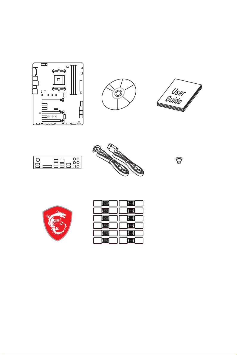
Unpacking
Thank you for buying the MSI® X470 GAMING PRO MAX motherboard. Check to make
sure your motherboard box contains the following items. If something is missing,
contact your dealer as soon as possible.
Motherboard
I/O Shield
Case Badge
Drivers & Utilities
Disc
SATA Cable x2
SATA Cable Labels
Motherboard User
Guide
M.2 Screw x2
Unpacking
1

Safety Information
y The components included in this package are prone to damage from electrostatic
discharge (ESD). Please adhere to the following instructions to ensure successful
computer assembly.
y Ensure that all components are securely connected. Loose connections may cause
the computer to not recognize a component or fail to start.
y Hold the motherboard by the edges to avoid touching sensitive components.
y It is recommended to wear an electrostatic discharge (ESD) wrist strap when
handling the motherboard to prevent electrostatic damage. If an ESD wrist strap is
not available, discharge yourself of static electricity by touching another metal object
before handling the motherboard.
y Store the motherboard in an electrostatic shielding container or on an anti-static pad
whenever the motherboard is not installed.
y Before turning on the computer, ensure that there are no loose screws or metal
components on the motherboard or anywhere within the computer case.
y Do not boot the computer before installation is completed. This could cause
permanent damage to the components as well as injury to the user.
y If you need help during any installation step, please consult a certified computer
technician.
y Always turn off the power supply and unplug the power cord from the power outlet
before installing or removing any computer component.
y Keep this user guide for future reference.
y Keep this motherboard away from humidity.
y Make sure that your electrical outlet provides the same voltage as is indicated on the
PSU, before connecting the PSU to the electrical outlet.
y Place the power cord such a way that people can not step on it. Do not place anything
over the power cord.
y All cautions and warnings on the motherboard should be noted.
y If any of the following situations arises, get the motherboard checked by service
personnel:
Liquid has penetrated into the computer.
The motherboard has been exposed to moisture.
The motherboard does not work well or you can not get it work according to user
guide.
The motherboard has been dropped and damaged.
The motherboard has obvious sign of breakage.
y Do not leave this motherboard in an environment above 60°C (140°F), it may damage
the motherboard.
Safety Information
2
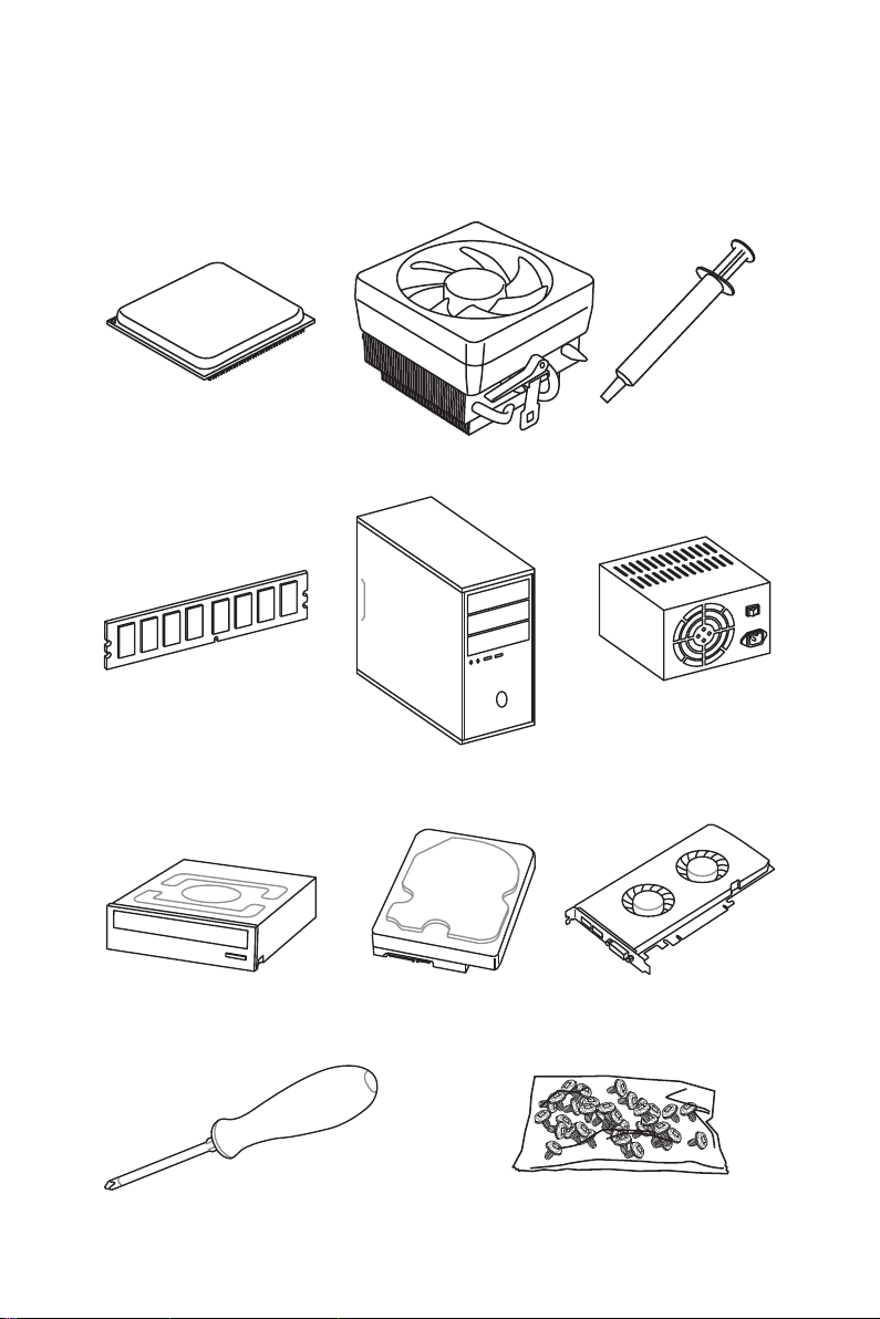
Quick Start
Preparing Tools and Components
AMD® AM4 CPU
DDR4 Memory
SATA DVD Drive
CPU Fan
Chassis
SATA Hard Disk Drive
Thermal Paste
Power Supply Unit
Graphics Card
Phillips Screwdriver
A Package of Screws
Quick Start
3
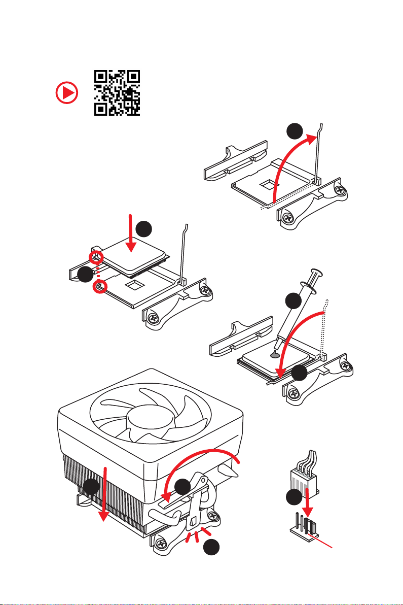
Installing a Processor
3
2
1
5
4
Quick Start
4
6
8
9
7
CPU_FAN1

Important
If you are installing the screw-type CPU heatsink, please follow the figure below to
remove the retention module first and then install the heatsink.
1
2
3
Quick Start
5
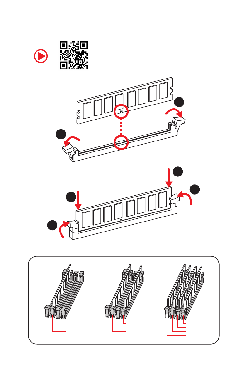
Installing DDR4 memory
1
2
1
2
3
Quick Start
6
3
DIMMB2 DIMMB2
DIMMA2 DIMMA2 DIMMA2
DIMMB1
DIMMA1
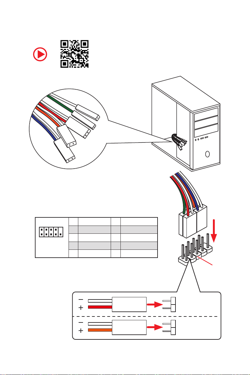
Connecting the Front Panel Header
RESET SW
POWER SW
POWER LED+
POWER LED-
HDD LED
2 10
1
JFP1
1 HDD LED + 2 Power LED +
3 HDD LED — 4 Power LED —
5 Reset Switch 6 Power Switch
9
7 Reset Switch 8 Power Switch
9 Reserved 10 No Pin
HDD LED
POWER LED
HDD LED
HDD LED HDD LED +
POWER LED POWER LED +
Quick Start
RESET SW
JFP1
7
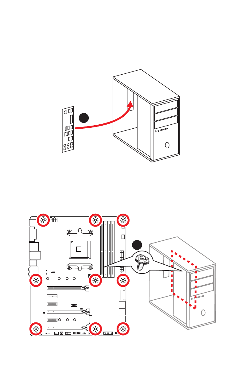
Installing the Motherboard
1
Quick Start
8
2
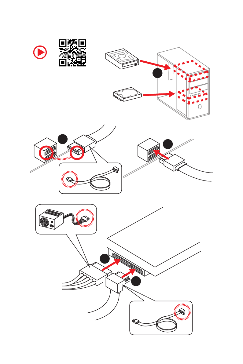
Installing SATA Drives
2
1
3
5
4
Quick Start
9
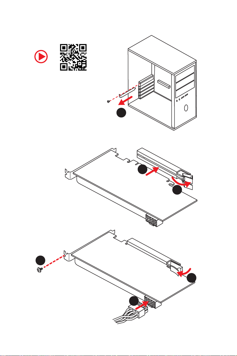
Installing a Graphics Card
1
3
2
10
5
4
6
Quick Start
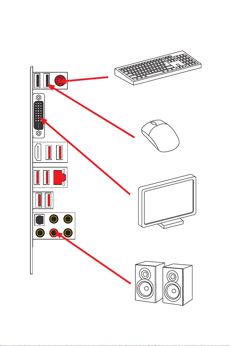
Connecting Peripheral Devices
Integrated Graphics Processing Unit (iGPU)
Quick Start
11
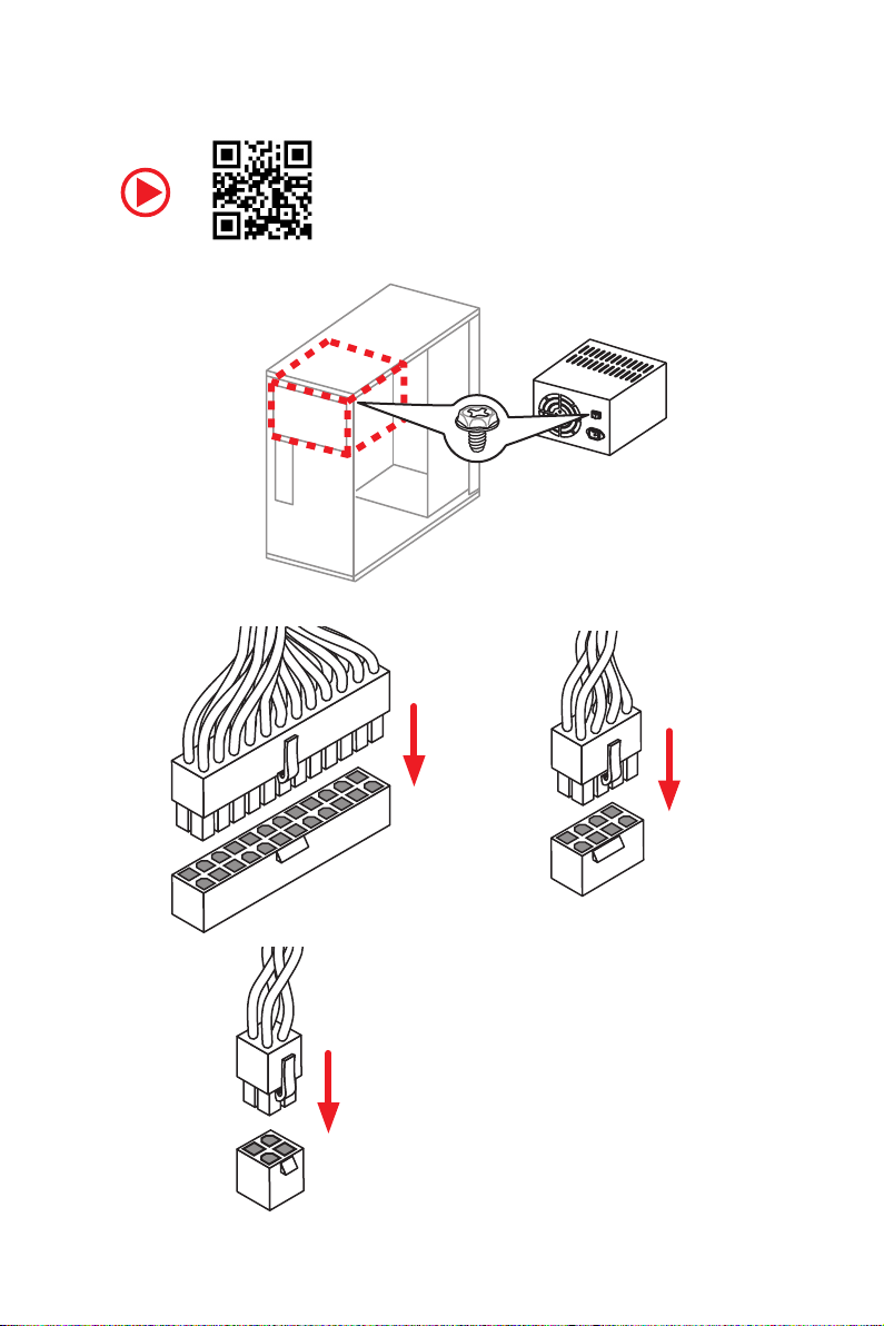
Connecting the Power Connectors
12
Quick Start
ATX_PWR1
CPU_PWR2
CPU_PWR1
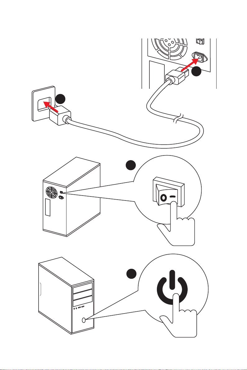
Power On
1
2
3
4
Quick Start
13

Contents
Unpacking ……………………………………………………………………………………………….. 1
Safety Information ……………………………………………………………………………………. 2
Quick Start ………………………………………………………………………………………………. 3
Preparing Tools and Components ……………………………………………………………….. 3
Installing a Processor ………………………………………………………………………………… 4
Installing DDR4 memory ……………………………………………………………………………. 6
Connecting the Front Panel Header …………………………………………………………….. 7
Installing the Motherboard …………………………………………………………………………. 8
Installing SATA Drives…………………………………………………………………………………9
Installing a Graphics Card ………………………………………………………………………… 10
Connecting Peripheral Devices …………………………………………………………………. 11
Connecting the Power Connectors …………………………………………………………….. 12
Power On………………………………………………………………………………………………… 13
Specifications …………………………………………………………………………………………. 17
Block Diagram ………………………………………………………………………………………. 22
Rear I/O Panel ………………………………………………………………………………………… 23
LAN Port LED Status Table……………………………………………………………………….. 23
Audio Ports Configuration ………………………………………………………………………… 23
Realtek HD Audio Manager ………………………………………………………………………. 24
Overview of Components ………………………………………………………………………… 26
CPU Socket …………………………………………………………………………………………….. 28
DIMM Slots ……………………………………………………………………………………………… 29
PCI_E1~6: PCIe Expansion Slots ……………………………………………………………….. 30
M2_1~2: M.2 Slots (Key M) ……………………………………………………………………….. 32
SATA1~6: SATA 6Gb/s Connectors …………………………………………………………….. 33
JLPT1: Parallel Port Connector ………………………………………………………………… 33
CPU_PWR1, CPU_PWR2, ATX_PWR1: Power Connectors ……………………………. 34
JUSB1~2: USB 2.0 Connectors ………………………………………………………………….. 35
JUSB3~4: USB 3.2 Gen1 Connectors …………………………………………………………. 35
CPU_FAN1, PUMP_FAN1, SYS_FAN1~4: Fan Connectors …………………………….. 36
JAUD1: Front Audio Connector ………………………………………………………………….37
JCI1: Chassis Intrusion Connector …………………………………………………………….. 37
JFP1, JFP2: Front Panel Connectors …………………………………………………………. 38
JTPM1: TPM Module Connector ………………………………………………………………… 38
JCOM1: Serial Port Connector ………………………………………………………………….. 39
JRGB1, JRGB2: RGB LED Connectors ……………………………………………………….. 39
JBAT1: Clear CMOS (Reset BIOS) Jumper ………………………………………………….. 40
14
Contents

CLR_CMOS1: Clear CMOS Button ……………………………………………………………… 40
BIOS Setup …………………………………………………………………………………………….. 41
Entering BIOS Setup ………………………………………………………………………………… 41
Resetting BIOS ………………………………………………………………………………………… 42
Updating BIOS …………………………………………………………………………………………. 42
EZ Mode …………………………………………………………………………………………………. 43
Advanced Mode ………………………………………………………………………………………. 45
SETTINGS ……………………………………………………………………………………………….. 46
Advanced ………………………………………………………………………………………………… 46
Boot ……………………………………………………………………………………………………….. 51
Security ………………………………………………………………………………………………….. 52
Save & Exit ……………………………………………………………………………………………… 54
OC ………………………………………………………………………………………………………….. 55
M-FLASH ……………………………………………………………………………………………….. 60
OC PROFILE ……………………………………………………………………………………………. 61
HARDWARE MONITOR ……………………………………………………………………………… 62
A-XMP Operation …………………………………………………………………………………….. 63
Software Description ………………………………………………………………………………. 64
Installing Windows® 10 …………………………………………………………………………….. 64
Installing Drivers …………………………………………………………………………………….. 64
Installing Utilities ……………………………………………………………………………………. 64
APP MANAGER ……………………………………………………………………………………….. 65
LIVE UPDATE 6 ………………………………………………………………………………………… 66
COMMAND CENTER ………………………………………………………………………………… 68
GAMING APP …………………………………………………………………………………………… 72
X-BOOST ………………………………………………………………………………………………… 77
MYSTIC LIGHT …………………………………………………………………………………………. 79
MYSTIC LIGHT PARTY ………………………………………………………………………………. 83
Joining Group ………………………………………………………………………………………….. 84
Group Control Panel ………………………………………………………………………………… 85
Inviting Member ………………………………………………………………………………………. 86
SMART TOOL …………………………………………………………………………………………… 87
RAMDISK………………………………………………………………………………………………… 89
Nahimic 2.5 …………………………………………………………………………………………….. 90
RAID Configuration …………………………………………………………………………………. 95
Using AMD RAID Controller BIOS Configuration Utility ………………………………… 95
Initialize Disks ………………………………………………………………………………………… 97
Create Arrays ………………………………………………………………………………………….. 98
Delete Arrays ………………………………………………………………………………………….. 99
Swap Arrays ………………………………………………………………………………………….. 100
Contents
15

Manage Spares ……………………………………………………………………………………… 101
Change the Controller Options ………………………………………………………………… 102
Booting the system from an array ……………………………………………………………. 102
Pausing the boot sequence for warning messages ……………………………………. 102
Change the Staggered Spinup Count ……………………………………………………….. 103
Using UEFI to create a 2.2TB RAID ………………………………………………………….. 104
Installing RAID Driver …………………………………………………………………………….. 105
Troubleshooting …………………………………………………………………………………… 106
16
Contents

Specifications
Supports 1st, 2nd and 3rd Gen AMD Ryzen™/ Ryzen™ with
CPU
Chipset AMD
Memory
Expansion Slots
Radeon™ Vega Graphics and 2nd Gen AMD Ryzen™ with
Radeon™ Graphics/ Athlon™ with Radeon™ Vega Graphics
Desktop Processors for Socket AM4
* Athlon™ with Radeon™ Vega Graphics processors support up to 2400 MHz. And
the supporting frequency of memory varies with installed processor. Please refer
www.msi.com for more information on compatible memory.
* PCI_E6 slot will be unavailable when installing M.2 PCIe SSD in M2_2 slot.
®
X470 Chipset
y 4x DDR4 memory slots, support up to 64GB
Supports DDR4 1866/ 2133/ 2400/ 2667 Mhz by JEDEC,
and 2667/ 2800/ 2933/ 3000/ 3066/ 3200/ 3466 Mhz by
A-XMP OC MODE*
y Dual channel memory architecture
y Supports non-ECC UDIMM memory
y Supports ECC UDIMM memory
y 2x PCIe 3.0 x16 slots (PCIE_1, PCIE_4)
1st, 2nd and 3rd Gen AMD Ryzen™ Processors support
x16/x0, x8/x8 mode
Ryzen™ with Radeon™ Vega Graphics and 2nd Gen AMD
Ryzen™ with Radeon™ Graphics Processors support x8/
x0 mode
Athlon™ with Radeon™ Vega Graphics Processors
support x4/x0 mode
y 1x PCIe 2.0 x16 slot (PCIE_6, supports x4 mode)*
y 3x PCIe 2.0 x1 slots
Onboard Graphics
y 1x DVI-D port, supports a maximum resolution of
1920×1200@60Hz*
y 1x HDMI™ port 1.4, supports a maximum resolution of
4096×2160@30Hz*
* Only support when using Radeon™ Vega Graphics and 2nd Gen AMD Ryzen™
with Radeon™ Graphics/ Athlon™ with Radeon™ Vega Graphics Processors
* Maximum shared memory of 2048 MB
Continued on next page
Specifications
17

Continued from previous page
y 1st, 2nd and 3rd Gen AMD Ryzen™ Processors
Supports 3-Way AMD
Multi-GPU
y Ryzen™ with Radeon™ Vega Graphics and 2nd Gen AMD
Ryzen™ with Radeon™ Graphics/ Athlon™ with Radeon™
Vega Graphics Processors
Supports 2-Way AMD
LAN 1x Realtek
®
CrossFire™ Technology
®
CrossFire™ Technology
®
8111H Gigabit LAN controller
Storage
RAID
USB
y 6x SATA 6Gb/s ports (from AMD
®
X470 Chipset)
y 2x M.2 ports (Key M)*
M2_1 slot (from AMD
®
processor) supports PCIe
3.0×4 (1st, 2nd and 3rd Gen AMD Ryzen™/ Ryzen™ with
Radeon™ Vega Graphics and 2nd Gen AMD Ryzen™ with
Radeon™ Graphics Processors) or PCIe 3.0×2 (Athlon™
with Radeon™ Vega Graphics Processors) 2242/ 2260
/2280/ 22110 storage devices
M2_2 slot (from AMD
®
X470 Chipset) supports PCIe 2.0
x4 and SATA 6Gb/s 2242/ 2260 /2280 storage devices
* SATA1 port will be unavailable when installing SATA M.2 SSD in M2_2 slot.
* PCI_E6 slot will be unavailable when installing PCIe M.2 SSD in M2_2 slot.
®
AMD
X470 Chipset
y Supports RAID 0, RAID 1 and RAID 10 for SATA storage
devices
y ASMedia
®
ASM1143 Chipset
2x USB 3.2 Gen2 (SuperSpeed USB 10Gbps) Type-A
ports on the back panel
®
y AMD
X470 Chipset
4x USB 3.2 Gen1 (SuperSpeed USB) ports through the
internal USB connectors
6x USB 2.0 (High-speed USB) ports (2 Type-A ports on
the back panel, 4 ports available through the internal
USB connectors)
®
y AMD
CPU
4x USB 3.2 Gen1 (SuperSpeed USB) Type-A ports on the
back panel
Specifications
18
Continued on next page

Audio
Back Panel
Connectors
Internal Connectors
Continued from previous page
®
y Realtek
ALC892 Codec
y 7.1-Channel High Definition Audio
y Supports S/PDIF output
y 1x PS/2 keyboard/ mouse combo port
y 2x USB 2.0 Type-A ports
y 1x DVI-D port
y 1x HDMI™ 1.4 port
y 4x USB 3.2 Gen1 Type-A ports
y 1x LAN (RJ45) port
y 2x USB 3.2 Gen2 Type-A ports
y 5x OFC audio jacks
y 1x Optical S/PDIF OUT connector
y 1x 24-pin ATX main power connector
y 1x 8-pin ATX 12V power connector
y 1x 4-pin ATX 12V power connector
y 6x SATA 6Gb/s connectors
y 2x USB 2.0 connectors (support additional 4 USB 2.0 ports)
y 2x USB 3.2 Gen1 connectors (support additional 4 USB 3.2
Gen1 ports)
y 1x 4-pin CPU fan connector
y 1x 4-pin PUMP fan connector (supports up to 2A)
y 4x 4-pin system fan connectors
y 1x Serial port connector
y 1x Parallel port connector
y 2x 5050 RGB LED strip 12V connectors
y 1x TPM module connector
y 1x Front panel audio connector
y 2x System panel connectors
y 1x Chassis Intrusion connector
y 1x Clear CMOS jumper
y 1x Clear CMOS button
Continued on next page
Specifications
19

Continued from previous page
I/O Controller NUVOTON NCT6795D Controller Chip
y CPU/System temperature detection
Hardware Monitor
y CPU/System fan speed detection
y CPU/System fan speed control
Form Factor
BIOS Features
Software
y ATX Form Factor
y 12 in. x 9.6 in. (30.5 cm x 24.4 cm)
y 1x 256 Mb flash
y UEFI AMI BIOS
y ACPI 6.1, SM BIOS 2.8
y Multi-language
y Drivers
y APP MANAGER
y COMMAND CENTER
y LIVE UPDATE 6
y MYSTIC LIGHT
y SUPER CHARGER
y GAMING APP
y RAMDISK
y X-BOOST
y SMART TOOL
y Nahimic Audio
y Open Broadcaster Software (OBS)
y Norton™ Internet Security Solution
y Google Chrome™, Google Toolbar, Google Drive
y CPU-Z MSI GAMING
Specifications
20
Continued on next page

Special Features
Continued from previous page
y Audio
Audio Boost
Voice Boost
Nahimic 2.5
y Storage
Turbo M.2
y Fan
Pump Fan
Smart Fan Control
y LED
Mystic Light
Mystic Light Extension
Mystic light SYNC
EZ DEBUG LED
y Protection
PCI-E Steel Armor
y Performance
Multi GPU-CrossFire Technology
DDR4 Boost
GAME Boost
X-Boost
A-XMP
y Stability
7000+ Quality Test
y VR
VR Ready
y Gamer Experience
RAMDisk
y BIOS
Click BIOS 5
y Certification
GAMING Certified
Specifications
21

Block Diagram
PCI Express Bus
PCIe x4 slot
Switch
1 x M.2
Switch
6 x SATA 6Gb/s
HDMI DVI-D
CPU
PCIex4
PCI Express Bus
2 Channel DDR4 Memory
NV6795
Super I/O
1 x M.2
4 x USB 3.2 Gen1
Realtek
ALC892
Audio Jacks
P/S2 Mouse / Keyboard
x1
PCIe x1 slot
x1
PCIe x1 slot
x1
PCIe x1 slot
Block Diagram
22
4 x USB 3.2 Gen1
6 x USB 2.0
X470
ASMEDIA
ASM1143
RTL8111H
2 x USB 3.2 Gen2

Rear I/O Panel
PS/2
DVI-D
USB 2.0
LAN Port LED Status Table
Link/ Activity LED
Status Description
Off No link
Yellow Linked
Blinking Data activity
USB 3.2 Gen1
LAN
USB 3.2 Gen2
USB 3.2 Gen1
Optical S/PDIF-Out
Speed LED
Status Description
Off 10 Mbps connection
Green 100 Mbps connection
Orange 1 Gbps connection
Audio Ports
Audio Ports Configuration
Audio Ports
Channel
2 4 6 8
Center/ Subwoofer Out ● ●
Rear Speaker Out ● ● ●
Line-In/ Side Speaker Out ●
Line-Out/ Front Speaker Out ● ● ● ●
Mic In
(●: connected, Blank: empty)
Rear I/O Panel
23

Realtek HD Audio Manager
After installing the Realtek HD Audio driver, the Realtek HD Audio Manager icon will
appear in the system tray. Double click on the icon to launch.
Device
Selection
Advanced
Settings
Application
Enhancement
Main Volume
Profiles
Jack Status
Connector
Settings
y Device Selection — allows you to select a audio output source to change the related
options. The check sign indicates the devices as default.
y Application Enhancement — the array of options will provide you a complete guidance
of anticipated sound effect for both output and input device.
y Main Volume — controls the volume or balance the right/left side of the speakers that
you plugged in front or rear panel by adjust the bar.
y Profiles — toggles between profiles.
y Advanced Settings — provides the mechanism to deal with 2 independent audio
streams.
y Jack Status — depicts all render and capture devices currently connected with your
computer.
y Connector Settings — configures the connection settings.
Auto popup dialog
When you plug into a device at an audio jack, a dialogue window will pop up asking you
which device is current connected.
Each jack corresponds to its default setting as shown on the next page.
Rear I/O Panel
24
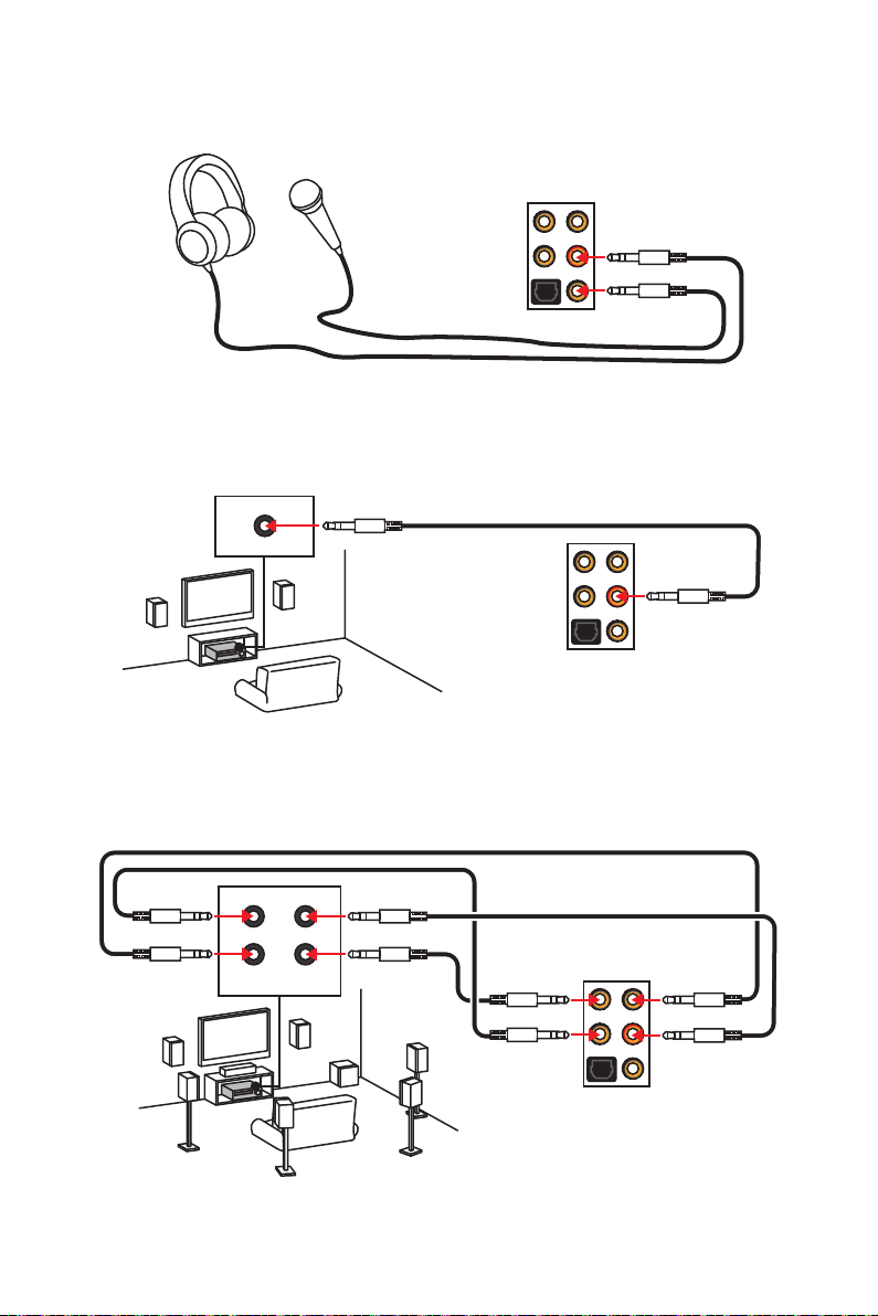
Audio jacks to headphone and microphone diagram
Audio jacks to stereo speakers diagram
AUDIO INPUT
Audio jacks to 7.1-channel speakers diagram
AUDIO INPUT
Rear Front
Side Center/
Subwoofer
Rear I/O Panel
25
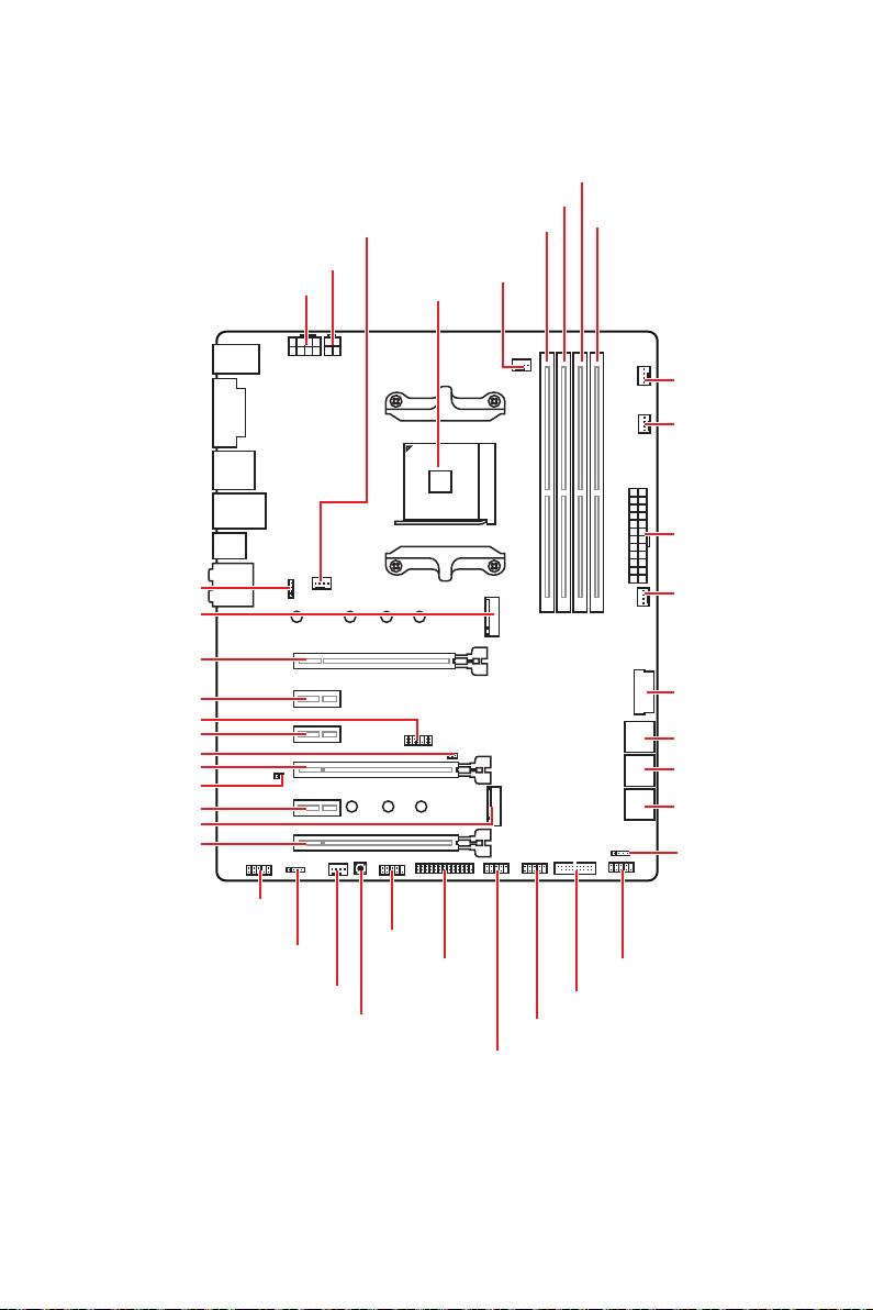
Overview of Components
SYS_FAN1
CPU_PWR2
CPU_PWR1
CPU Socket
DIMMA1
CPU_FAN1
DIMMB1
DIMMA2
DIMMB2
PUMP_FAN1
SYS_FAN3
ATX_PWR1
JRGB2
M2_1
PCI_E1
PCI_E2
JTPM1
PCI_E3
JCI1
PCI_E4
JBAT1
PCI_E5
M2_2
PCI_E6
JAUD1
JRGB1
SYS_FAN2
JCOM1
Clear CMOS
JLPT1
SYS_FAN4
JUSB4
SATA▼5▲6
SATA▼3▲4
SATA▼1▲2
JFP2
JFP1
JUSB3
JUSB2
JUSB1
Overview of Components
26

Component Contents
Port Name Port Type Page
CLR_CMOS1 Clear CMOS Button 40
CPU_FAN1, PUMP_FAN1,
SYS_FAN1~4
CPU_PWR1, CPU_PWR2,
ATX_PWR1
CPU Socket AM4 CPU Socket 28
DIMMA1, DIMMA2,
DIMMB1, DIMMB2
JAUD1 Front Audio Connector 37
JBAT1 Clear CMOS (Reset BIOS) Jumper 40
JCI1 Chassis Intrusion Connector 37
JCOM1 Serial Port Connector 39
JFP1, JFP2 Front Panel Connectors 38
JLPT1 Parallel Port Connector 33
JRGB1, JRGB2 RGB LED Connectors 39
JTPM1 TPM Module Connector 38
Fan Connectors 36
Power Connectors 34
DIMM Slots 29
JUSB1~2 USB 2.0 Connectors 35
JUSB3~4
M2_1~2 M.2 Slots (Key M) 32
PCI_E1~6 PCIe Expansion Slots 30
SATA1~6 SATA 6Gb/s Connectors 33
USB 3.2 Gen1 Connectors
Overview of Components
35
27
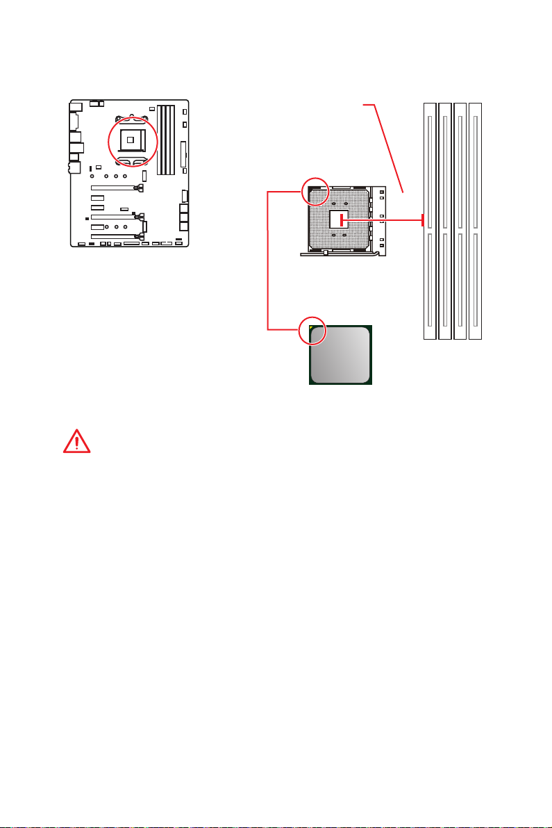
CPU Socket
Distance from the center of the
CPU to the nearest DIMM slot.
53.43
mm
Introduction to the AM4 CPU
The surface of the AM4 CPU has a
yellow triangle to assist in correctly
lining up the CPU for motherboard
placement. The yellow triangle is
the Pin 1 indicator.
Important
y
When changing the processor, the system configuration could be cleared and reset
BIOS to default values, due to the AM4 processor’s architecture.
y
Always unplug the power cord from the power outlet before installing or removing
the CPU.
y
When installing a CPU, always remember to install a CPU heatsink. A CPU heatsink
is necessary to prevent overheating and maintain system stability.
y
Confirm that the CPU heatsink has formed a tight seal with the CPU before booting
your system.
y
Overheating can seriously damage the CPU and motherboard. Always make sure
the cooling fans work properly to protect the CPU from overheating. Be sure to apply
an even layer of thermal paste (or thermal tape) between the CPU and the heatsink to
enhance heat dissipation.
y
If you purchased a separate CPU and heatsink/ cooler, Please refer to the
documentation in the heatsink/ cooler package for more details about installation.
y
This motherboard is designed to support overclocking. Before attempting to
overclock, please make sure that all other system components can tolerate
overclocking. Any attempt to operate beyond product specifications is not
recommended. MSI
operation beyond product specifications.
®
does not guarantee the damages or risks caused by inadequate
Overview of Components
28
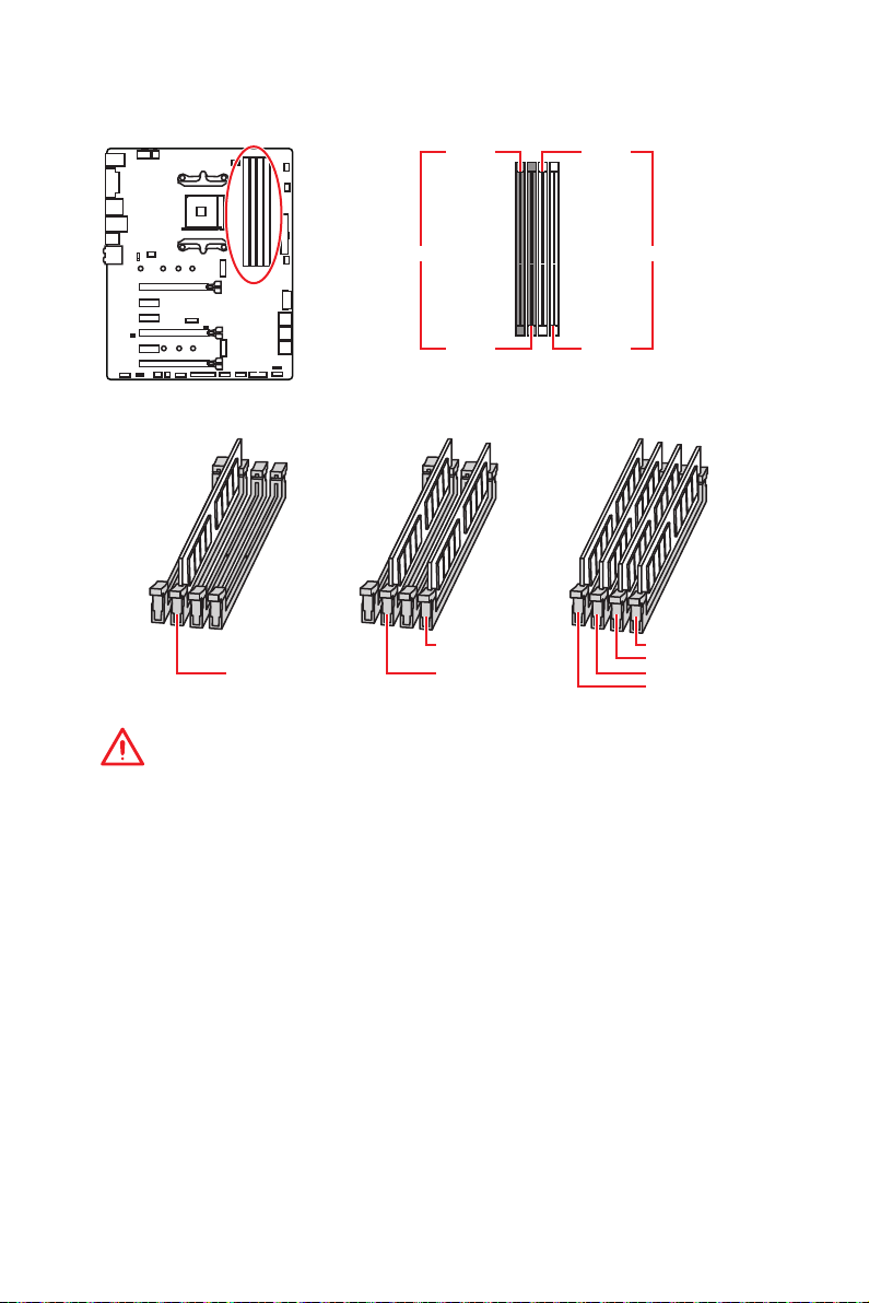
DIMM Slots
DIMMA1 DIMMB1
Channel A Channel B
DIMMA2 DIMMB2
Memory module installation recommendation
DIMMB2 DIMMB2
DIMMA2 DIMMA2 DIMMA2
DIMMB1
DIMMA1
Important
y
Always insert memory modules in the DIMMA2 slot first.
y
Due to chipset resource usage, the available capacity of memory will be a little less
than the amount of installed.
y
Based on the processor specification, the Memory DIMM voltage below 1.35V is
suggested to protect the processor.
y
Some memory modules may operate at a lower frequency than the marked value
when overclocking due to the memory frequency operates dependent on its Serial
Presence Detect (SPD). Go to BIOS and find the DRAM Frequency to set the memory
frequency if you want to operate the memory at the marked or at a higher frequency.
y
It is recommended to use a more efficient memory cooling system for full DIMMs
installation or overclocking.
y
The stability and compatibility of installed memory module depend on installed CPU
and devices when overclocking.
y
Due to AM4 CPU/memory controller official specification limitation, the frequency of
memory modules may operate lower than the marked value under the default state.
Please refer www.msi.com for more information on compatible memory.
Overview of Components
29
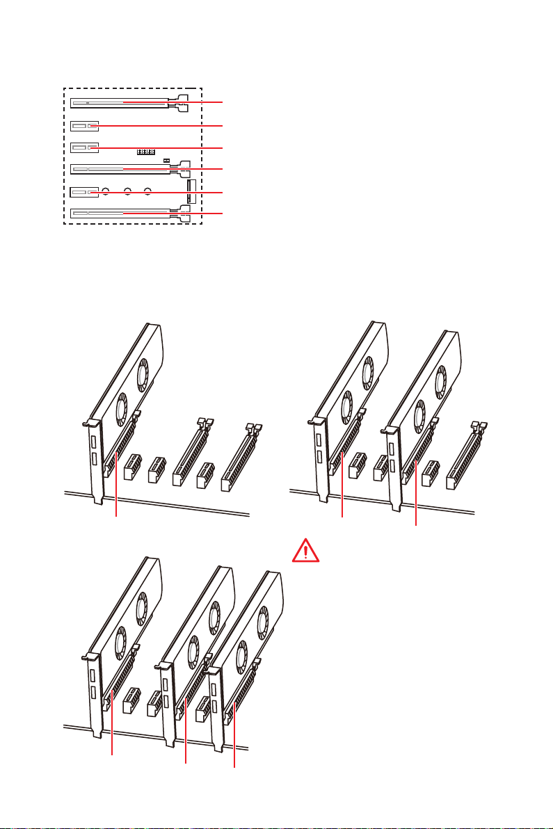
PCI_E1~6: PCIe Expansion Slots
PCI_E1: PCIe 3.0 x16*/ PCIe 3.0 x8**/ PCIe 3.0 x4***
PCI_E2: PCIe 2.0 x1
PCI_E3: PCIe 2.0 x1
PCI_E4: PCIe 3.0 x8*/ Unavailable**/ Unavailable***
PCI_E5: PCIe 2.0 x1
PCI_E6: PCIe 2.0 x4
* For 1st, 2nd and 3rd Gen AMD Ryzen™ Processors
** Ryzen™ with Radeon™ Vega Graphics and 2nd Gen AMD Ryzen™ with Radeon™
Graphics Processors
*** Athlon™ with Radeon™ Vega Graphics Processors
Multiple graphics cards installation recommendation (Ryzen™ series
processors)
x16
x8
Overview of Components
30
x8
x8
Important
y
If you install a large and heavy
graphics card, you need to use a tool
such as MSI Gaming Series Graphics
Card Bolster to support its weight to
prevent deformation of the slot.
y
For a single PCIe x16 expansion card
installation with optimum performance,
using the PCI_E1 slot is recommended.
y
When adding or removing expansion
cards, always turn off the power supply
and unplug the power supply power
cable from the power outlet. Read the
expansion card’s documentation to
check for any necessary additional
hardware or software changes.
x8
x4
Loading…
I
Quick Start
Quick Start
Thank you for purchasing the MSI
®
X470 GAMING PRO MAX
motherboard. This Quick Start section provides demonstration
diagrams about how to install your computer. Some of the
installations also provide video demonstrations. Please link to the
URL to watch it with the web browser on your phone or tablet. You
may have even link to the URL by scanning the QR code.
MSI
®
X470 GAMING PRO MAX
PC
URL
QR URL
MSI
®
X470 GAMING PRO MAX .
.
URL . QR
URL .
MSI
®
X470 GAMING PRO MAX
URL QR
code
MSI
®
X470 GAMING PRO MAX
QRURL

I
Quick Start
Quick Start
Thank you for purchasing the MSI
®
X470 GAMING PLUS MAX
motherboard. This Quick Start section provides demonstration
diagrams about how to install your computer. Some of the
installations also provide video demonstrations. Please link to the
URL to watch it with the web browser on your phone or tablet. You
may have even link to the URL by scanning the QR code.
Kurzanleitung
Danke, dass Sie das MSI
®
X470 GAMING PLUS MAX Motherboard
gewählt haben. Dieser Abschnitt der Kurzanleitung bietet eine Demo
zur Installation Ihres Computers. Manche Installationen bieten
auch die Videodemonstrationen. Klicken Sie auf die URL, um diese
Videoanleitung mit Ihrem Browser auf Ihrem Handy oder Table
anzusehen. Oder scannen Sie auch den QR Code mit Ihrem Handy,
um die URL zu öffnen.
Présentation rapide
Merci d’avoir choisi la carte mère MSI
®
X470 GAMING PLUS MAX.
Ce manuel fournit une rapide présentation avec des illustrations
explicatives qui vous aideront à assembler votre ordinateur. Des
tutoriels vidéo sont disponibles pour certaines étapes. Cliquez sur
le lien fourni pour regarder la vidéo sur votre téléphone ou votre
tablette. Vous pouvez également accéder au lien en scannant le QR
code qui lui est associé.
Быстрый старт
Благодарим вас за покупку материнской платы MSI
®
X470
GAMING PLUS MAX. В этом разделе представлена информация,
которая поможет вам при сборке комьютера. Для некоторых
этапов сборки имеются видеоинструкции. Для просмотра
видео, необходимо открыть соответствующую ссылку в
веб—браузере на вашем телефоне или планшете. Вы также
можете выполнить переход по ссылке, путем сканирования
QR-кода.
Смотреть руководство для MSI X470 Gaming Plus Max ниже. Все руководства на ManualsCat.com могут просматриваться абсолютно бесплатно. Нажав кнопку «Выбор языка» вы можете изменить язык руководства, которое хотите просмотреть.
MANUALSCAT | RU
Вопросы и ответы
У вас есть вопрос о MSI X470 Gaming Plus Max, но вы не можете найти ответ в пользовательском руководстве? Возможно, пользователи ManualsCat.com смогут помочь вам и ответят на ваш вопрос. Заполните форму ниже — и ваш вопрос будет отображаться под руководством для MSI X470 Gaming Plus Max. Пожалуйста, убедитесь, что вы опишите свои трудности с MSI X470 Gaming Plus Max как можно более детально. Чем более детальным является ваш вопрос, тем более высоки шансы, что другой пользователь быстро ответит на него. Вам будет автоматически отправлено электронное письмо, чтобы проинформировать вас, когда кто-то из пользователей ответит на ваш вопрос.
Задать вопрос о MSI X470 Gaming Plus Max
Страница: 1
1
Содержание
Содержание
Безопасное использование продукции……………………………………………… 2
Технические характеристики……………………………………………………………… 3
Задняя панель портов ввода/ вывода ……………………………………………….. 8
Таблица состояний индикатора порта LAN…………………………………………… 8
Конфигурация портов Аудио…………………………………………………………………. 8
Менеджер Realtek HD Audio…………………………………………………………………….. 9
Компоненты материнской платы……………………………………………………… 11
Процессорный сокет ……………………………………………………………………………. 12
Слоты DIMM ………………………………………………………………………………………….. 13
PCI_E1~6: Слоты расширения PCIe……………………………………………………….. 14
M2_1~2: Разъем M.2 (Ключ M)………………………………………………………………… 16
SATA1~6: Разъемы SATA 6Гб/с ……………………………………………………………….. 17
JLPT1: Разъем параллельного порта……………………………………………………. 17
CPU_PWR1, CPU_PWR2, ATX_PWR1: Разъемы питания ………………………….. 18
JUSB1~2: Разъемы USB 2.0…………………………………………………………………….. 19
JUSB3~4: Разъемы USB 3.2 Gen1 ……………………………………………………………. 19
CPU_FAN1, PUMP_FAN1, SYS_FAN1~4: Разъемы вентиляторов……………… 20
JAUD1: Разъем аудио передней панели……………………………………………….. 21
JCI1: Разъем датчика открытия корпуса ……………………………………………… 21
JFP1, JFP2: Разъемы передней панели ………………………………………………… 22
JTPM1: Разъем модуля TPM ………………………………………………………………….. 22
JCOM1: Разъем последовательного порта …………………………………………… 23
JRGB1, JRGB2: Разъем RGB LED…………………………………………………………….. 23
JBAT1: Джампер очистки данных CMOS (Сброс BIOS)…………………………… 24
CLR_CMOS1: Кнопка очистки данных CMOS…………………………………………. 24
Настройка BIOS …………………………………………………………………………………… 25
Вход в настройки BIOS …………………………………………………………………………. 25
Сброс BIOS ……………………………………………………………………………………………. 26
Обновление BIOS………………………………………………………………………………….. 26
Режим EZ ………………………………………………………………………………………………. 27
Режим разгона …………………………………………………………………………………….. 29
Меню OC ……………………………………………………………………………………………….. 30
Описание программного обеспечения…………………………………………….. 35
Установка Windows®
10………………………………………………………………………….. 35
Установка драйверов …………………………………………………………………………… 35
Установка утилит …………………………………………………………………………………. 35
Страница: 2
2 Безопасное использование продукции
Безопасноеиспользованиепродукции
y Компоненты, входящие в комплект поставки могут быть повреждены
статическим электричеством. Для успешной сборки компьютера,
пожалуйста, следуйте указаниям ниже.
y Убедитесь, что все компоненты компьютера подключены должным
образом. Ослабленные соединения компонентов могут привести как к сбоям
в работе, так и полной неработоспособности компьютера.
y Чтобы избежать повреждений компонентов платы всегда держите ее за
края.
y При сборке комьютера рекомендуется пользоваться электростатическим
браслетом. В случае, если это невозможно, перед работой с платой снимите
электростатический заряд со своего тела, прикоснувшись к металлическому
предмету.
y В случае, если материнская плата не установлена в корпус, храните ее в
антистатической упаковке или на антистатическом коврике.
y Перед включением компьютера убедитесь, что все винты крепления и
другие металлические компоненты на материнской плате и внутри корпуса
надежно зафиксированы.
y Не включайте компьютер, если сборка не завершена. Это может привести к
повреждению компонентов, а также травмированию пользователя.
y Если вам нужна помощь на любом этапе сборки компьютера, пожалуйста,
обратитесь к сертифицированному компьютерному специалисту.
y Всегда выключайте питание и отсоединяйте шнур питания от
электрической розетки перед установкой или удалением любого
компонента компьютера.
y Сохраните это руководство для справки.
y Не допускайте воздействия на материнскаую плату высокой влажности.
y Перед тем как подключить блок питания компьютера к электрической
розетке убедитесь, что напряжение электросети соответствует напряжению,
указанному на блоке питания.
y Располагайте шнур питания так, чтобы на него не могли наступить люди.
Не ставьте на шнур питания никаких предметов.
y Необходимо учитывать все предостережения и предупреждения,
указанные на материнской плате.
y При возникновении любой из перечисленных ниже ситуаций обратитесь в
сервисный центр для проверки материнской платы:
Попадание жидкости внутрь компьютера.
Материнская плата подверглась воздействию влаги.
Материнская плата не работает должным образом или невозможно
наладить ее работу в соответствии с руководством пользователя.
Материнская плата получила повреждения при падении.
Материнская плата имеет явные признаки повреждения.
y Не храните материнскую плату в местах с температурой выше 60 °C (140 °F),
так как это может привести к ее повреждению.the motherboard.
Страница: 3
3
Технические характеристики
Технические характеристики
Процессор
Поддержка процессоров AMD Ryzen™ 1-го, 2-го и
3-го поколения/ процессоров Ryzen™ с видеокартой
Radeon™ Vega и процессоров AMD Ryzen™ 2-го
поколения с видеокартой Radeon™/ процессоров
Athlon™ для настольных ПК с видеокартой Radeon™
Vega для сокета AM4
Чипсет AMD®
X470
Память
y 4x слота памяти DDR4 с поддержкой до 64 ГБ
Поддержка DDR4 1866/ 2133/ 2400/ 2667 МГц по
стандартам JEDEC, и 2667/ 2800/ 2933/ 3000/ 3066/
3200/ 3466 МГц с поддержкой A-XMP OC MODE*
y Двухканальная архитектура памяти
y Поддержка non-ECC UDIMM памяти
y Поддержка ECC UDIMM памяти
* Процессоры Athlon™ с видеокартой Radeon™ Vega максимально
поддерживают 2400 МГц. Поддерживающая частота памяти зависит
от моделя установленного процессора. Пожалуйста, обратитесь www.
msi.com для получения дополнительной информации о совместимых
памяти.
Слоты
расширения
y 2x слота PCIe 3.0 x16 (PCIE_1, PCIE_4)
Процессоры AMD Ryzen™ 1-го, 2-го и 3-го
поколения поддерживают режим x16/x0, x8/x8
Процессоры Ryzen™ с видеокартой Radeon™
Vega и процессоры AMD Ryzen™ 2-го поколения с
видеокартой Radeon™ поддерживают режим x8/x0
Процессоры Athlon™ с видеокартой Radeon™ Vega
поддерживают режим x4/x0
y 1x слот PCIe 2.0 x16 (PCIE_6, поддержка режима x4)*
y 3x слота PCIe 2.0 x1
* Слот PCI_E6 будет недоступен при установке M.2 PCIe SSD в разъеме
M2_2.
Встроенная
графика
y 1x порт DVI-D, с поддержкой максимального
разрешения 1920×1200@60Гц*
y 1x порт HDMI™ 1.4, с поддержкой максимального
разрешения 4096×2160@30Гц*
* Поддерживается только при использовании процессоров Ryzen™ с
видеокартой Radeon™ Vega и процессоров AMD Ryzen™ 2-го поколения
с видеокартой Radeon™/ процессоров Athlon™ с видеокартой Radeon™
Vega
* Максимальная общая память — 2048 МБ
Продолжение на следующей странице
Страница: 4
4 Технические характеристики
Продолжение с предыдущей страницы
Поддержка Multi-
GPU
y Процессоры AMD Ryzen™ 1-го, 2-го и 3-го поколения
Поддержка технологии 3-Way AMD®
CrossFire™
y Процессоры Ryzen™ с видеокартой Radeon™
Vega и процессоры AMD Ryzen™ 2-го поколения
с видеокартой Radeon™/ процессоры Athlon™ с
видеокартой Radeon™ Vega
Поддержка технологии 2-Way AMD®
CrossFire™
LAN 1x Гигабитный сетевой контроллер Realtek®
8111H
Подключение
накопителей
y 6x портов SATA 6Гб/с (для чипсета AMD®
X470)
y 2x разъема M.2 (Ключ M)*
Разъем M2_1 (для процессоров AMD®
)
поддерживает PCIe 3.0×4 (AMD Ryzen™ 1-го, 2-го и
3-го поколения/ Ryzen™ с видеокартой Radeon™
Vega и AMD Ryzen™ 2-го поколения с видеокартой
Radeon™) или PCIe 3.0×2 (Athlon™ с видеокартой
Radeon™ Vega), накопителей 2242/ 2260 /2280/ 22110
Разъем M2_2 (для чипсета AMD®
X470)
поддерживает накопители PCIe 2.0 x4 или SATA
6Gb/s 2242/ 2260 /2280
* Порт SATA1 будет недоступен при усановке SATA M.2 SSD в разъеме
M2_2.
* Слот PCI_E6 будет недоступен при усановке PCIe M.2 SSD в разъеме
M2_2.
RAID
Чипсет AMD®
X470
y Поддержка RAID 0, RAID 1 и RAID 10 для накопителей
SATA
USB
y Контроллер ASMedia®
ASM1143
2x порта USB 3.2 Gen2 (SuperSpeed USB 10Гб/с)
Type-A на задней панели
y Контроллер AMD®
X470
4x порта USB 3.2 Gen1 (SuperSpeed USB) доступны
через внутренние разъемы USB
6x портов USB 2.0 (High-speed USB) (2 порта
Type-A на задней панели, 4 порта доступны через
внутренние разъемы USB)
y Контроллер процессора AMD®
4x порта USB 3.2 Gen1 (SuperSpeed USB) Type-A на
задней панели
Продолжение на следующей странице
Страница: 5
5
Технические характеристики
Продолжение с предыдущей страницы
Аудио
y Realtek®
ALC892 Codec
y 7.1-канальный High Definition Audio
y Поддержка выхода S/PDIF-out
Разъемы задней
панели
y 1x комбинированный порт PS/2 клавиатуры/ мыши
y 2x порта USB 2.0 Type-A
y 1x порт DVI-D
y 1x порт HDMI™ 1.4
y 4x порта USB 3.2 Gen1 Type-A
y 1x порт LAN (RJ45)
y 2x порта USB 3.2 Gen2 Type-A
y 5x аудиоразъемов OFC
y 1x оптический разъем S/PDIF-OUT
Разъемы на плате
y 1x 24-контактный разъем питания ATX 12В
y 1x 8-контактный разъем питания ATX 12В
y 1x 4-контактный разъем питания ATX 12В
y 6x разъемов SATA 6Гб/с
y 2x разъема USB 2.0 (поддержка 4-х дополнительных
портов USB 2.0)
y 2x разъема USB 3.2 Gen1 (поддержка 4-х
дополнительных портов USB 3.2 Gen1)
y 1x 4-контактный разъем вентилятора процессора
y 1x 4-контактный разъем вентилятора PUMP
(поддержка до 2А)
y 4x 4-контактных разъема вентилятора системы
y 1x разъем последовательного порта
y 1x разъем параллельного порта
y 2x разъема 5050 RGB LED лент 12В
y 1x разъем модуля TPM
y 1x разъем аудио передней панели
y 2x разъема системной панели
y 1x разъем датчика открытия корпуса
y 1x джампер очистки данных CMOS
y 1x кнопка очистки данных CMOS
Продолжение на следующей странице
Страница: 6
6 Технические характеристики
Продолжение с предыдущей страницы
Контроллер
ввода-вывода
NUVOTON NCT6795D
Аппаратный
мониторинг
y Определение температуры процессора/системы
y Определение скорости вентиляторов процессора/
системы
y Управление скоростью вентиляторов процессора/
системы
Форм-фактор
y ATX Форм-фактор
y 12 x 9.6 дюйма (30.5 x 24.4 см)
Параметры BIOS
y 1x 256 Мб флэш
y UEFI AMI BIOS
y ACPI 6.1, SM BIOS 2.8
y Мультиязычный интерфейс
Программное
обеспечение
y Драйверы
y APP MANAGER
y COMMAND CENTER
y LIVE UPDATE 6
y MYSTIC LIGHT
y SUPER CHARGER
y GAMING APP
y RAMDISK
y X-BOOST
y SMART TOOL
y Nahimic Audio
y Open Broadcaster Software (OBS)
y Norton™ Internet Security Solution
y Google Chrome™, Google Toolbar, Google Drive
y CPU-Z MSI GAMING
Продолжение на следующей странице
Страница: 7
7
Технические характеристики
Продолжение с предыдущей страницы
Эксклюзивные
функции
y Аудио
Audio Boost
Voice Boost
Nahimic 2.5
y Накопитель
Turbo M.2
y Вентирятор
Pump Fan
Интеллектуальное управление вентилятором
y Индикатор
Mystic Light
Mystic Light Extension
Mystic light SYNC
EZ DEBUG LED
y Защита
PCI-E Steel Armor
y Производительность
Multi GPU-CrossFire Technology
DDR4 Boost
GAME Boost
X-Boost
A-XMP
y Стабильность
7000+ Quality Test
y VR
VR Ready
y Ощущение игроков
RAMDisk
y BIOS
Click BIOS 5
y Certification
GAMING Certified
Страница: 8
8 Задняя панель портов ввода/ вывода
Конфигурация портов Аудио
Порты Аудио
Канал
2 4 6 8
Выход центральной
колонки/ сабвуфера
● ●
Тыловые колонки ● ● ●
Линейный вход/ Выход
боковых колонок
●
Линейный выход/ Выход
фронтальных колонок
● ● ● ●
Микрофонный вход
(●: подключен, Пусто: не подключен)
Задняя панель портов ввода/ вывода
Подключение/ Работа
индикатора
Состояние Описание
Выкл. Не подключен
Желтый Подключен
Мигает Передача данных
Скорость передачи данных
Состояние Описание
Выкл. 10 Мбит/с подключение
Зеленый 100 Мбит/с подключение
Оранжевый 1 Гбит/с подключение
Таблица состояний индикатора порта LAN
LAN
USB 2.0
PS/2
Порты Аудио
Оптический
S/PDIF-Out
USB 3.2 Gen1
USB 3.2 Gen1
USB 3.2 Gen2
DVI-D
Страница: 9
9
Задняя панель портов ввода/ вывода
Менеджер Realtek HD Audio
После установки драйвера Realtek HD Audio, в системном трее появится
значок Realtek HD Audio Manager. Дважды щелкните по значку для запуска
приложения.
y Выбор устройства — позволяет выбрать источник аудио выхода и изменить
соответствующие параметры. Отмеченное устройство будет использоваться
по умолчанию.
y Дополнительные эффекты — это список опций по настройке звуковых
эффектов для входного и выходного сигнала аудио устройства.
y Мастер-громкость — регулирует громкость или баланс правой и левой
колонок, подключенных к передней или задней панели.
y Профили — позволяют переключаться между различными профилями.
y Расширенные настройки — обеспечивают работу с двумя независимыми
потоками аудио.
y Состояние разъемов — отображает все устройства воспроизведения и
записи, подключенные к компьютеру.
y Настройки подключений — настраивают параметры подключения.
Автоматическое всплывающее диалоговое окно
При подключении устройства к разъему аудио появится диалоговое окно с
просьбой подтвердить подключенное устройство.
Каждый разъем соответствует его настройкам по умолчанию, как показано
на следующей странице.
Состояние
разъемов
Выбор
устройства
Настройки
подключений
Профили
Мастер-
громкость
Дополнительные
эффекты
Расширенные
настройки
Страница: 10
10 Задняя панель портов ввода/ вывода
AUDIO INPUT
Rear Front
Side Center/
Subwoofer
Подключение наушников и микрофона
Подключение внешнего стерео усилителя (колонок)
Подключение звуковой системы 7.1
AUDIO INPUT
Страница: 11
11
Компоненты материнской платы
Компоненты материнской платы
SATA▼3▲4
SATA▼1▲2
SATA▼5▲6
CPU_FAN1
JRGB1
JRGB2
PUMP_FAN1
PCI_E1
PCI_E2
PCI_E3
PCI_E4
PCI_E5
PCI_E6
JTPM1
Процессорный
сокет
CPU_PWR1
CPU_PWR2
JBAT1
M2_2
M2_1
DIMMA1
SYS_FAN1
DIMMA2
DIMMB1
DIMMB2
JLPT1
JUSB1
JUSB2
JFP2
JFP1
JAUD1
ATX_PWR1
SYS_FAN3
SYS_FAN4
SYS_FAN2
Clear CMOS
JCOM1
JUSB4
JCI1
JUSB3
Страница: 12
12 Компоненты материнской платы
Процессорный сокет
Процессор AM4
На поверхности процессора AM4
имеется золотой треугольник
для правильной установки
процессора относительно
процессорного сокета
материнской платы. Золотой
треугольник указывает на
контакт 1.
Внимание!
y Из-за особенностей архитектуры процессоров АМ4, замена процессора
может привести к сбросу настроек BIOS до значений по умолчанию.
y Перед установкой или заменой процессора, необходимо отключить кабель
питания.
y При установке процессора обязательно установите процессорный
кулер. Кулер, представляющий собой систему охлаждения процессора,
предотвращает перегрев и обеспечивает стабильную работу системы.
y Перед включением системы проверьте герметичность соединения между
процессором и радиатором.
y Перегрев может привести к серьезному повреждению процессора и
материнской платы. Всегда проверяйте работоспособность вентилятора для
защиты процессора от перегрева. При установке кулера нанесите ровный
слой термопасты (или термоленту) на крышку установленного процессора
для улучшения теплопередачи.
y Если вы приобрели отдельно процессор и процессорный кулер, подробное
описание установки см. в документации в данному кулеру.
y Данная системная плата разработана с учетом возможности ее
«разгона». Перед выполнением разгона системы убедитесь в том, что все
компоненты системы смогут его выдержать. Производитель не рекомендует
использовать параметры, выходящие за пределы технических характеристик
устройств. Гарантия MSI®
не распространяется на повреждения и другие
возможные последствия ненадлежащей эксплуатации оборудования.
53.43
мм
Расстояние от центра
процессора до ближайшего
слота DIMM.
Страница: 13
13
Компоненты материнской платы
Слоты DIMM
Внимание!
y Всегда устанавливайте модуль памяти сначала в слот DIMMA2.
y В связи со спецификой использования ресурсов чипсета, доступный объем
памяти будет немного меньше, чем фактически установленный.
y На основе характеристик процессора, рекомендуется устанавливать
напряжение на памяти DIMM менее 1.35 В. Это позволит защитить
процессор.
y Некоторые модули памяти при разгоне могут работать на частотах ниже
заявленной производителем, поскольку выставляемая для памяти частота
зависит от информации, записанной в SPD (Serial Presence Detect). Зайдите в
BIOS и выберите опцию DRAM Frequency, чтобы установить заявленную или
более высокую частоту.
y При установке памяти во все слоты, а также при ее разгоне, рекомендуется
использовать более эффективную систему охлаждения памяти.
y Совместимость и стабильность работы установленного модуля памяти при
разгоне зависит от установленного процессора и других устройств.
y Из-за ограничений официальной спецификации процессора АМ4/
контроллера памяти, модули памяти могут работать на частотах
ниже заявленной производителем при насройках по умолчанию.
Дополнительную информацию о совместимых модулях памяти можно найти
на веб-сайте www.msi.com.
DIMMA1 DIMMB1
Канал A Канал B
DIMMA2 DIMMB2
Рекомендации по установке модулей памяти
DIMMB2 DIMMB2
DIMMB1
DIMMA2 DIMMA2 DIMMA2
DIMMA1
Страница: 14
14 Компоненты материнской платы
Рекомендации по установке нескольких видеокарт (для
процессоров серии RYZEN™)
x16 x8
x8
x8
x8 x4
Внимание!
y При установке массивной видеокарты,
необходимо использовать такой
инструмент, как MSI Gaming Series
Graphics Card Bolster для поддержки
веса графической карты и во избежание
деформации слота.
y Для установки одной карты
расширения PCIe x16 с оптимальной
производительностью рекомендуется
использовать слот PCI_E1.
y Перед установкой или извлечением
плат расширения убедитесь, что кабель
питания отключен от электрической
сети. Прочтите документацию на карту
расширения и выполните необходимые
дополнительные аппаратные или
программные изменения для данной
карты.
PCI_E4: PCIe 3.0 x8*/ Недоступно**/ Недоступно***
PCI_E1~6: Слоты расширения PCIe
PCI_E2: PCIe 2.0 x1
PCI_E3: PCIe 2.0 x1
PCI_E5: PCIe 2.0 x1
PCI_E6: PCIe 2.0 x4
PCI_E1: PCIe 3.0 x16*/ PCIe 3.0 x8**/ PCIe 3.0 x4***
* Для процессоров AMD Ryzen™ 1-го, 2-го и 3-го поколения
** Для процессоров Ryzen™ с видеокартой Radeon™ Vega и процессоров AMD
Ryzen™ 2-го поколения с видеокартой Radeon™
*** Для процессоров Athlon™ с видеокартой Radeon™ Vega
Страница: 15
15
Компоненты материнской платы
Таблица пропускной способности PCIe
Для процессоров AMD Ryzen™ 1-го, 2-го и 3-го поколения
Слот Одинарный 2-Way
PCI_E1 (CPU) Gen 3.0 x 16* Gen 3.0 x 8*
PCI_E2 (PCH) Gen 2.0 x 1 Gen 2.0 x 1
PCI_E3 (PCH) Gen 2.0 x 1 Gen 2.0 x 1
PCI_E4 (CPU) ─ Gen 3.0 x 8*
PCI_E5 (PCH) Gen 2.0 x 1 Gen 2.0 x 1
PCI_E6 (PCH) Gen 2.0 x 4 ─ Gen 2.0 x 4 ─
M2_1 (CPU) Gen 3.0 x 4 Gen 3.0 x 4
M2_2 (PCH) ─ Gen 2.0 x 4 ─ Gen 2.0 x 4
(─: недоступно, *: видеокарта)
Для процессоров Ryzen™ с видеокартой Radeon™ Vega и процессоров AMD
Ryzen™ 2-го поколения с видеокартой Radeon™
Слот Одинарный
PCI_E1 (CPU) Gen 3.0 x 8*
PCI_E2 (PCH) Gen 2.0 x 1
PCI_E3 (PCH) Gen 2.0 x 1
PCI_E4 (CPU) ─
PCI_E5 (PCH) Gen 2.0 x 1
PCI_E6 (PCH) Gen 2.0 x 4 ─
M2_1 (CPU) Gen 3.0 x 4
M2_2 (PCH) ─ Gen 2.0 x 4
(─: недоступно, *: видеокарта)
Для процессоров Athlon™ с видеокартой Radeon™ Vega
Слот Одинарный
PCI_E1 (CPU) Gen 3.0 x 4*
PCI_E2 (PCH) Gen 2.0 x 1
PCI_E3 (PCH) Gen 2.0 x 1
PCI_E4 (CPU) ─
PCI_E5 (PCH) Gen 2.0 x 1
PCI_E6 (PCH) Gen 2.0 x 4 ─
M2_1 (CPU) Gen 3.0 x 2
M2_2 (PCH) ─ Gen 2.0 x 4
(─: недоступно, *: видеокарта)
Внимание!
Слот PCI_E6 будет недоступен при установке PCIe M.2 SSD в разъеме M2_2.
Страница: 16
16 Компоненты материнской платы
M2_1~2: Разъем M.2 (Ключ M)
Видео Инструкция
Смотрите видео, чтобы узнать как установить M.2 SSD.
Установка M.2 SSD
30°
2. Закрутите стойку
для крепления M.2
модуля в подходящее
отверстие, в
соответствии с длиной
вашего M.2 SSD.
3. Вставьте M.2 SSD в
разъем М.2 под углом
30 градусов.
4. Закрепите M.2
SSD с помощью
прилагаемого винта
для M.2.
1. Выкрутите стойку
для крепления
M.2 модуля из
материнской платы.
Прилагаемый винт
для M.2
Внимание!
y Порт SATA1 будет недоступен при установке SATA
M.2 SSD в разъеме M2_2.
y Слот PCI_E6 будет недоступен при установке PCIe
M.2 SSD в разъеме M2_2.
y Разъем M2_1 только поддерживает режим PCIe.
M2_1
M2_2
Страница: 17
17
Компоненты материнской платы
SATA1~6: Разъемы SATA 6Гб/с
Эти разъемы представляют собой интерфейсные порты SATA 6Гб/с. К
каждому порту можно подключить одно устройство SATA.
SATA5
SATA3
SATA1
SATA6
SATA4
SATA2
Внимание!
y Порт SATA1 будет недоступен при установке SATA M.2 SSD в разъеме M2_2.
y Избегайте перегибов кабеля SATA под прямым углом. В противном случае,
возможна потеря данных при передаче.
y Кабели SATA оснащены одинаковыми коннекторами с обеих сторон.
Однако, для экономии занимаемого пространства к материнской плате
рекомендуется подключать плоский разъем.
1
2 26
25
1 RSTB# 2 AFD# 3 PRND0
4 ERR# 5 PRND1 6 PINIT#
7 PRND2 8 LPT_SLIN# 9 PRND3
10 Ground 11 PRND4 12 Ground
13 PRND5 14 Ground 15 PRND6
16 Ground 17 PRND7 18 Ground
19 ACK# 20 Ground 21 BUSY
22 Ground 23 PE 24 Ground
25 SLCT 26 No Pin
JLPT1: Разъем параллельного порта
Данный разъем позволяет подключить параллельный порт, размещенный
на внешнем бракете.
Страница: 18
18 Компоненты материнской платы
24
13
1
12
ATX_PWR1
1 +3.3V 13 +3.3V
2 +3.3V 14 -12V
3 Ground 15 Ground
4 +5V 16 PS-ON#
5 Ground 17 Ground
6 +5V 18 Ground
7 Ground 19 Ground
8 PWR OK 20 Res
9 5VSB 21 +5V
10 +12V 22 +5V
11 +12V 23 +5V
12 +3.3V 24 Ground
5
4 1
8
CPU_PWR1
1 Ground 5 +12V
2 Ground 6 +12V
3 Ground 7 +12V
4 Ground 8 +12V
Внимание!
Для обеспечения стабильной работы системной платы проверьте
надежность подключения всех кабелей питания к блоку питания АТХ.
CPU_PWR1, CPU_PWR2, ATX_PWR1: Разъемы питания
Данные разъемы предназначены для подключения блока питания ATX.
3
2 1
4
CPU_PWR2
1 Ground 3 +12V
2 Ground 4 +12V
Страница: 19
19
Компоненты материнской платы
JUSB3~4: Разъемы USB 3.2 Gen1
Данные разъемы предназначены для подключения портов USB 3.2 Gen1 на
передней панели.
Внимание!
Помните, что во
избежание повреждений,
необходимо правильно
подключать контакты
питания и земли.
1 10
11
20
JUSB3
1
10 11
20
JUSB4
1 Power 11 USB2.0+
2 USB3_RX_DN 12 USB2.0-
3 USB3_RX_DP 13 Ground
4 Ground 14 USB3_TX_C_DP
5 USB3_TX_C_DN 15 USB3_TX_C_DN
6 USB3_TX_C_DP 16 Ground
7 Ground 17 USB3_RX_DP
8 USB2.0- 18 USB3_RX_DN
9 USB2.0+ 19 Power
10 NC 20 No Pin
JUSB1~2: Разъемы USB 2.0
Данные разъемы предназначены для подключения портов USB 2.0 на
передней панели.
1
2 10
9
1 VCC 2 VCC
3 USB0- 4 USB1-
5 USB0+ 6 USB1+
7 Ground 8 Ground
9 No Pin 10 NC
Внимание!
y Помните, что во избежание повреждений, необходимо правильно
подключать контакты VCC и земли.
y Для того, чтобы зарядить ваш iPad, iPhone и iPod через порты USB,
пожалуйста, установите утилиту MSI®
SUPER CHARGER.
Страница: 20
20 Компоненты материнской платы
CPU_FAN1, PUMP_FAN1, SYS_FAN1~4: Разъемы вентиляторов
Разъемы вентиляторов можно разделить на два типа: с PWM (PulseWidth
Modulation) управлением и управлением постоянным током. Разъемы
вентиляторов с PWM управлением имеют контакт с постоянным напряжением
12В, а также контакт с сигналом управления скоростью вращения.
Управление скоростью вращения вентиляторов с управлением постоянным
током, осуществляется через соответсвующие разъемы путем изменения
величины напряжения. Поэтому, при подключении 3-х контактного (Non-
PWM) вентилятора к разъему для вентилятора PWM, скорость вентилятора
всегда будет максимальной. Работа такого вентилятора может оказаться
достаточно шумной. CPU_FAN1 и PUMP_FAN1 могут автоматически определить
режим работы вентилятора — PWM или DC. Для настройки режима работы
вентилятора вручную (PWM или DC), следуйте указаниям ниже.
Назначение контактов разъема для режима
PWM
1 Ground 2 +12V
3 Sense 4 Speed Control Signal
Назначение контактов разъема для
режима DC
1 Ground 2 Voltage Control
3 Sense 4 NC
Разъем вентилятора с PWM управлением по
умолчанию
Разъем вентилятора с управлением
постоянным током по умолчанию
Переключение режимов работы и скорости вращения вентилятора
В меню BIOS > HARDWARE MONITOR вы можете выбрать режим работы
вентилятора: PWM или DC и настроить его скорость вращения.
Выберите режим PWM, DC или Auto
Внимание!
Убедитесь, что вентиляторы работают правильно после выбора режима PWM/ DC.
Вы можете регулировать скорость вращения вентилятора
в зависимости от температуры процессора путем
изменения положения градиентных точек.
1
SYS_FAN1/ SYS_FAN3/ SYS_FAN4
1
SYS_FAN2
1
CPU_FAN1
Назначение контактов разъема для подключения вентилятора
Разъем вентилятора с автоматическим
управлением по умолчанию
1
PUMP_FAN1
Страница: 21
21
Компоненты материнской платы
JAUD1: Разъем аудио передней панели
Данный разъем предназначен для подключения аудиоразъемов передней
панели.
1
2 10
9
1 MIC L 2 Ground
3 MIC R 4 NC
5 Head Phone R 6 MIC Detection
7 SENSE_SEND 8 No Pin
9 Head Phone L 10 Head Phone Detection
JCI1: Разъем датчика открытия корпуса
К этому разъему подключается кабель от датчика открытия корпуса.
Нормально
(По умолчанию)
Разрешить запись
по событию
открытия корпуса
Использование датчика открытия корпуса
1. Подключите датчик открытия корпуса к разъему JCI1.
2. Закройте крышку корпуса.
3. Войдите в BIOS > Settings > Security > Chassis Intrusion Configuration.
4. Установите Chassis Intrusion в Enabled.
5. Нажмите клавишу F10, чтобы сохранить настройки и выйти, а затем
нажмите клавишу Enter, чтобы выбрать Yes.
6. При открытии корпуса на экране будет появляться предупреждающее
сообщение каждый раз при включении компьютера.
Сброс сообщения об открытии корпуса
1. Войдите в BIOS > Settings > Security > Chassis Intrusion Configuration.
2. Выберите Chassis Intrusion, Reset.
3. Нажмите клавишу F10, чтобы сохранить настройки и выйти, а затем
нажмите клавишу Enter, чтобы выбрать Yes.
Страница: 22
22 Компоненты материнской платы
1
2 14
13
1 LPC Clock 2 3V Standby power
3 LPC Reset 4 3.3V Power
5 LPC address & data pin0 6 Serial IRQ
7 LPC address & data pin1 8 5V Power
9 LPC address & data pin2 10 No Pin
11 LPC address & data pin3 12 Ground
13 LPC Frame 14 Ground
JTPM1: Разъем модуля TPM
Данный разъем используется для подключения модуля ТРМ (Trusted Platform
Module). Дополнительные сведения см. в описании модуля ТРМ.
JFP1, JFP2: Разъемы передней панели
Эти разъемы служат для подключения кнопок и светодиодных индикаторов,
расположенных на передней панели.
1
2 10
9
JFP1
1 HDD LED + 2 Power LED +
3 HDD LED — 4 Power LED —
5 Reset Switch 6 Power Switch
7 Reset Switch 8 Power Switch
9 Reserved 10 No Pin
1
JFP2
1 Speaker — 2 Buzzer +
3 Buzzer — 4 Speaker +
Страница: 23
23
Компоненты материнской платы
JRGB1, JRGB2: Разъем RGB LED
Разъем JRGB1/JRGB2 предназначен для подключения светодиодных лент
5050 RGB 12В и кулера процессора AMD с RGB светодионой подсветкой.
Внимание!
y Разъем JRGB1/JRGB2 поддерживает подключение 5050 RGB светодиодных
лент (12В/G/R/B) с мощностью 3А (12В).
y Обратите внимание, что длина лент должна быть не более 2 метров, иначе
яркость свечения будет падать.
y Перед установкой или заменой светодиодных лент RGB, необходимо
полностью обесточить систему и отключить кабель питания.
y Используйте утилиту MSI®
для управления удлинительными
светодиодными лентами.
1
JRGB1/
JRGB2
JRGB1
JRGB2
Удлинительный
кабель
5050 RGB LED ленты 12В
1
JRGB1
JRGB2
1 +12V 2 G
3 R 4 B
1
2 10
9
1 DCD 2 SIN
3 SOUT 4 DTR
5 Ground 6 DSR
7 RTS 8 CTS
9 RI 10 No Pin
JCOM1: Разъем последовательного порта
Данный разъем позволяет подключить последовательный порт,
размещенный на внешнем бракете.
Страница: 24
24 Компоненты материнской платы
JBAT1: Джампер очистки данных CMOS (Сброс BIOS)
На плате установлена CMOS память с питанием от батарейки для хранения
данных о конфигурации системы. Для сброса конфигурации системы
(очистки данных CMOS памяти), воспользуйтесь этим джампером.
Сохранение данных
(По умолчанию)
Очистка данных/
Сброс BIOS
Сброс настроек BIOS до значений по умолчанию
1. Выключите компьютер и отключите шнур питания.
2. Используйте джампер, чтобы замкнуть соответствующие контакты JBAT1
в течение 5-10 секунд.
3. Снимите джампер с контактов JBAT1.
4. Подключите шнур питания и включите компьютер.
CLR_CMOS1: Кнопка очистки данных CMOS
Выключите компьютер. Нажмите и удерживайте кнопку очистки данных
CMOS на 5-10 секунд для сброса настройки BIOS по умолчанию.
Кнопка очистки
данных CMOS
Страница: 25
25
Настройка BIOS
Настройка BIOS
Настройки по умолчанию обеспечивают оптимальную производительность
и стабильность системы при нормальных условиях. Если вы недостаточно
хорошо знакомы с BIOS, всегда устанавливайте настройки по умолчанию.
Это позволит избежать возможных повреждений системы, а также проблем
с загрузкой.
Внимание!
y С целью улучшения производительности, меню BIOS постоянно
обновляется. В связи с этим данное описание может немного отличаться
от последней версии BIOS и может использоваться в качестве справки. Для
описания какого либо пункта меню настроек BIOS, вы можете обратиться к
информационной панели HELP.
y Изображения в этой главе приведены исключительно в справочных целях
и могут отличаться от фактических.
Вход в настройки BIOS
Нажмите клавишу Delete, когда появляется сообщение на экране Press DEL
key to enter Setup Menu, F11 to enter Boot Menu во время загрузки.
Функциональные клавиши
F1: Общая справка
F2: Добавить / Удалить избранный предмет
F3: Вход в меню Избранное
F4: Вход в меню технических параметров процессора
F5: Вход в меню Memory-Z
F6: Загрузить оптимизированные настройки по умолчанию
F7: Переключить между расширенном режимом и режимом EZ
F8: Загрузить профиль разгона
F9: Сохранить профиль разгона
F10: Сохранение изменений и перезагрузка*
F12: Сделать скриншот и сохранить его на USB флэш-диск (только FAT /
FAT32 формат).
Ctrl+F: Вход в страницу поиска
* При нажатии клавиши F10 появится информационное окно. Выберите Yes
или No, чтобы подтвердить выбор.
Страница: 26
26 Настройка BIOS
Сброс BIOS
В некоторых ситуациях необходиимо выполнить восстановление настроек
BIOS до значений по умолчанию. Существует несколько способов сброса
настроек:
y Войдите в BIOS и нажмите клавишу F6 для загрузки оптимизированных
значений по умолчанию.
y Замкните джампер Clear CMOS на материнской плате.
Внимание!
Убедитесь, что компьютер выключен перед очисткой данных CMOS.
Для получения дополнительной информации о сбросе настроек BIOS,
обратитесь к разделу
“Джампер очистки данных CMOS”
.
Обновление BIOS
Обновление BIOS при помощи M-FLASH
Подготовительные операции:
Пожалуйста, скачайте последнюю версию файла BIOS с сайта MSI, который
соответствует вашей модели материнской платы. Сохраните файл BIOS на
флэш-диске USB.
Обновление BIOS:
1. Вставьте флэш-диск USB, содержащий файл обновления в компьютер.
2. Нажмите клавиши <Ctrl+F5> во время процедуры POST.
3. Нажмите на кнопку Yes для перезагрузки системы и входа в режим
обновления.
4. Выберите файл BIOS для выполнения процесса обновления BIOS.
5. После завершения процесса обновления, система перезагрузится
автоматически.
Обновление BIOS при помощи Live Update 6
Перед обновлением:
Убедитесь, что драйвер локальной сети установлен и есть подключение к
сети Интернет.
Обновление BIOS:
1. Установите и запустите MSI LIVE UPDATE 6.
2. Выберите BIOS Update.
3. Нажмите на кнопку Scan.
4. Нажмите на значок Download, чтобы загрузить и установить последнюю
версию файла BIOS.
5. Нажмите кнопку Next и выберите In Windows mode. И затем нажмите
кнопку Next и Start для запуска обновления BIOS.
6. По завершению процесса обновления, система перезагрузится
автоматически.
Страница: 27
27
Настройка BIOS
Режим EZ
Режим EZ предоставляет основную информацию о системе и позволяет
выполнить основные операции по настройке. Для настройки расширенных
функций BIOS, пожалуйста, войдите в Расширенный режим, путем нажатия
Переключатель режимов установки или при помощи функциональной
клавиши F7.
Экран
просмотра
информации
Информация
о системе
Приоритет
загрузочных
устройств
Функциональные
клавиши
Язык
Поиск
Скриншот
Переключатель
режимов установки
M-Flash
Избранное
Аппаратный
мониторинг
Переключатель
GAME BOOST
Переключатель A-XMP
y Переключатель GAME BOOST — щелкните для переключения GAME BOOST в
ОС.
Внимание!
Для сохранения оптимальной производительность и стабильности системы
после активации функции GAME BOOST, пожалуйста, не делайте никаких
изменений в меню OC и не загружайте настройки по умолчанию.
y Переключатель A-XMP (опционально) — нажмите на внутренний
значок, чтобы включить/ выключить A-XMP. Для выбора профиля памяти
переключите внешний значок. Этот переключатель доступен только в
случае, если установлен модуль памяти с подержкой данной функции.
y Переключатель режимов установки — нажмите эту вкладку или клавишу
F7, чтобы переключиться между режимами EZ и разгона.
y Скриншот — нажмите на эту вкладку или клавишу F12, чтобы сделать
скриншот и сохранить его на флэш-диск USB (только FAT/ FAT32).
y Поиск — кликните по данной вкладке или нажмите клавиши Ctrl + F для
перехода на страницу поиска. Это позволяет выполнить поиск по имени
параметра BIOS. Для вывода списка пунктов BIOS, введите имя параметра.
Наведите указатель мыши на пустое место и щелкните правой кнопкой
мыши, для выхода со страницы поиска.
Внимание!
На странице поиска доступны только функциональные клавиши F6, F10 и
F12.
y Язык — позволяет выбрать язык интерфейса для настройки BIOS.
Страница: 28
28 Настройка BIOS
y Информация о системе — показывает частоту процессора/ памяти,
температуру процессора/ материнской платы, информацию о материнской
плате/процессоре, размер памяти, напряжение на процессоре/ памяти,
версию BIOS и дату создания.
y Приоритет загрузочных устройств — вы можете переместить инонку
устройства для изменения приоритета загрузки. Приоритет загрузки
устанавливается слева направо, от высокого к низкому.
y Экран просмотра информации — нажмите на кнопку CPU, Memory, Storage,
Fan Info и Help в левой части экрана для отображения соответствующей
информации.
y Функциональные клавиши — включают или выключают LAN Option ROM,
HD audio controller, Window 10 WHQL Support, AHCI, RAID, CPU Fan Fail Warning
Control и BIOS Log Review, при нажатии на соответствующую кнопку.
Внимание!
y В процессе установки Windows может потребоваться драйвер RAID. Вы
можете найти драйвер на диске MSI с драйверами из комплекта поставки.
y Вы также можете использовать MSI SMART TOOL для создания установочного
диска Windows®
, который будет включать драйвер RAID.
y В случае удаления созданного ранее RAID массива через настройки UEFI
BIOS, ваша система не сможет быть загружена.
y M-Flash — нажмите на эту кнопку для отображения меню M-Flash. Пункт
позволяет выбрать способ обновления BIOS при помощи USB флеш
накопителя.
y Аппаратный мониторинг — нажмите на эту кнопку для отображения
меню аппаратного мониторинга. Пункт позволяет вручную регулировать
скорость вращения вентиляторов в процентах.
y Избранное — нажмите на данную кнопку или клавишу F3 для входа в меню
Избранное. Позволяет создать личное меню BIOS, где вы можете сохранить
и получить доступ к вашим любимым и часто используемым настройкам
BIOS.
Главная страница по умолчанию — позволяет выбрать меню BIOS
(например, параметры, OC…, и т.д.) в качестве главной страницы BIOS.
Избранное1~5 — позволяет добавлять наиболее часто используемые /
любимые пункты настройки BIOS на одну страницу.
Добавление пункта BIOS в страницу Избранное (избранное 1~5)
1. Выберите пункт BIOS в настройках OC или меню OC.
2. Щелкните правой кнопкой мыши или нажмите клавишу F2.
3. Выберите любимую страницу и нажмите на кнопку OK.
Удаление пункта BIOS из страницы Избранное
1. Выберите пункт BIOS на странице Избранное (избранное 1~5).
2. Щелкните правой кнопкой мыши или нажмите клавишу F2.
3. Выберите Delete и нажмите на кнопку OK.
Страница: 29
29
Настройка BIOS
Режим разгона
Нажмите переключатель режимов установки или функциональную
клавишу F7 для переключения между режимами EZ и разгона в настройках
BIOS.
Переключатель A-XMP
Переключатель
GAME BOOST
Информация
о системе
Приоритет
загрузочных
устройств
Выбор меню
BIOS
Язык
Поиск
Скриншот
Переключатель
режимов установки
Экран меню
Выбор меню
BIOS
y Переключатель GAME BOOST/ Переключатель режимов установки/
Скриншот/ Изобранное/ Язык/ Информация о системе/ Приоритет
загрузочных устройств — пожалуйста, обратитесь к разделу Режим EZ.
y Выбор меню BIOS — доступны следующие опции:
SETTINGS — в данном меню представлены настройки чипсета и
загрузочных устройств.
OC — позволяют регулировать частоту и напряжение. Увеличение
частоты приводит к увеличению производительности.
M-FLASH — позволяет выбрать метод обновления BIOS с USB флэш-диска.
OC PROFILE — позволяет управлять профилями разгона.
HARDWARE MONITOR — позволяет установить скорость работы
вентиляторов и мониторинг напряжений системы.
BOARD EXPLORER — предоставляет информации об установленных
устройствах на материнской плате.
y Экран меню — отображаются настройки BIOS и дополнительная
информация.
Страница: 30
30 Настройка BIOS
Меню OC
Данное меню предназначено для опытных пользователей и предоставляет
возможности для «разгона» системы.
Внимание!
y Разгонять ПК вручную рекомендуется только опытным пользователям.
y Производитель не гарантирует успешность разгона. Неправильное
выполнение разгона может привести к аннулированию гарантии и
серьезному повреждению оборудования.
y Неопытным пользователям рекомендуется использовать функцию GAME
BOOST.
y Пункты BIOS в меню OC будут меняться в зависимости от моделя
процессора.
f OC Explore Mode [Normal]
Включение или выключение отображения нормального или экспертного
режима настроек разгона.
[Normal] Стандартные параметры разгона в BIOS.
[Expert] Расширенные параметры разгона в BIOS для опытных
пользователей.
Примечание: Символом * отмечаются параметры разгона в режиме Expert.
f CPU Ratio [Auto]
Задание множителя процессора для установки его тактовой частоты. Этот
пункт появляется при установке процессора с поддержкой данной функции.
f Core Performance Boost [Auto]
Включение или выключение Core Performance Boost (CPB). Этот пункт
появляется при установке процессора с поддержкой данной функции.
f Downcore Control [Auto] (опционально)
Задание количество используемых ядер процессора. Этот пункт появляется
при установке процессора с поддержкой данной функции.
f A-XMP [Disabled]
Включите A-XMP или выберите профиль модуля памяти для разгона. Данный
пункт доступен, когда установлен модуль памяти, процессора и материнской
платы с поддержкой данной функции.
Страница: 31
31
Настройка BIOS
f DRAM Frequency [Auto]
Установка частоты памяти DRAM. Обратите внимание, что возможность
успешного разгона не гарантируется.
f Memory Try It ! [Disabled]
Позволяет улучшить совместимость памяти и производительность, путем
выбора наиболее оптимального пресета.
f Memory Retry Count [5]
Устанавливает количество попыток разгона памяти. При неудачном разгоне,
установка значения данного пункта в [5], позволяет перезагрузить систему
5 раз в той же разогнанной конфигурации. При неудачной попытке разгона,
параметры системы будут восстановлены по умолчанию.
f Advanced DRAM Configuration (опционально)
Нажмите Enter для входа в подменю. Пользователь может настроить
тайминги для каждого канала памяти. Система может работать нестабильно
или не загружаться после изменения тамингов памяти. Если система
работает нестабильно, пожалуйста, очистите данные CMOS и восстановите
настройки по умолчанию. (см. перемычка очистки данных CMOS/раздел
кнопки для очистки данных CMOS и вход в BIOS, чтобы загрузить настройки
по умолчанию.)
f DigitALL Power
Нажмите Enter для входа в подменю. Функция управляет цепями питания,
связанными с PWM процессора.
fCPU Loadline Calibration Control [Auto]
Напряжение на процессоре уменьшается пропорционально, в
зависимости от его загрузки. Повышение значения Load-line Calibration
приводит к повышению напряжения и производительности при разгоне,
но и увеличивает температуру процессора и VRM. При установке в Auto,
BIOS установит данный параметр автоматически.
fCPU Over Voltage Protection [Auto]
Устанавливает верхнюю границу максимального напряжения для защиты
процессора от повышенного напряжения. Если установлено Auto, BIOS
автоматически настроит этот параметр. Чем выше значение, тем ниже
степень защиты и выше вероятность выхода системы из строя.
fCPU Under Voltage Protection [Auto]
Устанавливает нижнюю границу напряжения для защиты процессора от
пониженного напряжения. Если установлено Auto, BIOS автоматически
настроит этот параметр. Чем выше значение, тем ниже степень защиты и
выше вероятность выхода системы из строя.
fCPU Over Current Protection [Auto]
Устанавливает ограничение по максимальному току для защиты
процессора. При устанвке в Auto, BIOS автоматически настроит этот
параметр.
[Auto] Этот параметр будет настроен автоматически с помощью
BIOS.
[Enhanced] Расширяет ограничение по току от перегрузки по току.
Страница: 32
32 Настройка BIOS
fCPU Switching Frequency [Auto]
Устанавливает скорость работы PWM для стабилизации напряжения ядра
процессора и минимизации диапазона пульсаций. Увеличение рабочей
частоты PWM приводит к сильному нагреву MOSFET. Перед тем как
увеличить значение убедитесь, что охлаждение для MOSFET установлено.
При установке в Auto, BIOS автоматически настроит этот параметр.
fCPU VRM Over Temperature Protection [Auto]
Устанавливает верхнее значение температуры на CPU VRM для защиты
от перегрева. Частота CPU может быть регулируются, когда CPU VRM
над заданной температуры. При установке в Auto, BIOS настроит этот
параметр.
fCPU Power Duty Control[Thermal Balance]
Установка максимального тока для каждой фазы и температурного
режима работы для каждого компонента VRM.
[Thermal Balance] Поддерживает тепловой баланс VRM.
[Current Balance] Поддерживает токовый баланс VRM.
fCPU NB Loadline Calibration Control [Auto]
Настройка одного определенного режима CPU NB Loadline calibration при
полной нагрузке системы для получения высокой производительности
и стабильности при разгоне. При установке в Auto, BIOS автоматически
настроит этот параметр.
fCPU NB Over Current Protection [Auto]
Установка ограничения по току для защиты CPU NB. Если установлено в
Auto, BIOS автоматически настроит этот параметр.
[Auto] Этот параметр будет настроен автоматически с помощью
BIOS.
[Enhanced] Расширяет ограничение по току от перегрузки по току.
fCPU NB Switching Frequency [Auto]
Установка рабочей частоты PWM для стабилизации напряжения CPU-NB и
минимизации диапазона пульсаций. Увеличение частоты PWM приводит
к более сильному нагреву MOSFET транзисторов. Перед увеличением
частоты, необходимо обеспечить хорошее охлаждение транзисторов
MOSFET. При установке в Auto, BIOS автоматически настроит этот
параметр.
fCPU NB Power Duty Control [Thermal Balance]
Установка максимального тока для каждой фазы и температурного
режима работы для каждого компонента CPU-NB VRM.
[Thermal Balance] Поддерживает тепловой баланс VRM.
[Current Balance] Поддерживает токовый баланс VRM.
fVR 12VIN OCP Expander [Auto]
Расширяет ограничение по току регуляторов напряжения для защиты
процессора с входным напряжением 12В. Чем выше значение, тем ниже
степень защиты. Будьте аккуратны при настройке текущего значения, в
противном случае регуляторы напряжения процессора могут выйти из
строя. При установке в Auto, BIOS автоматически настроит этот параметр.
Страница: 33
33
Настройка BIOS
f CPU Voltages control [Auto]
Эти параметры позволяют вам задать напряжения, связанные с
процессором. При установке в Auto, BIOS установит напряжения
автоматически. Вы также можете настроить напряжения вручную.
f DRAM Voltages control [Auto]
Эти параметры позволяют вам задать напряжения, связанные с памятью.
При установке в Auto, BIOS установит напряжения автоматически. Вы также
можете настроить напряжения вручную.
f Memory Changed Detect [Enabled]*
Включение или выключение предупреждающих сообщений при загрузке
системы, когда процессор или память были заменены.
[Enabled] Система выдает предупреждение во время загрузки. Требуется
загрузить настройки по умолчанию для новых устройств.
[Disabled] Выключение этой функии и сохранение текущих настроек BIOS.
f CPU Specifications
Нажмите Enter для входа в подменю. В этом подменю представлена
информация об установленном процессоре. Для просмотра этой
информации в любое время нажмите на кнопку [F4]. Это значение нельзя
изменять.
fCPU Technology Support
Нажмите Enter для входа в подменю. В данном подменю отображаются
основные функции, поддерживаемые установленным процессором. Это
значение нельзя изменять.
f MEMORY-Z
Нажмите Enter для входа в подменю. В подменю выделены все параметры и
тайминги установленной памяти. Для просмотра этой информации в любое
время нажмите на кнопку [F5].
fDIMMx Memory SPD
Нажмите Enter для входа в подменю. Это подменю показывает
информацию об установленной памяти. Это значение нельзя изменять.
f CPU Features
Нажмите Enter для входа в подменю.
fSimultaneous Multi-Threading [Enabled] (опционально)
Включение или выключение AMD Simultaneous Multi-Threading. Этот пункт
появляется при установке процессора с поддержкой данной функции.
fGlobal C-state Control [Enabled] (опционально)
Включение или выключение IO based C-state generation и DF C-states.
fOpcache Control [Auto] (опционально)
Включение или выключение Opcache. Opcache сохраняет последние
команды декодирования для сокращения времени исполнения
повторной команды. Включение данной функции может увеличить
производительность процессора и немного снизить энергопотребление.
Страница: 34
34 Настройка BIOS
fIOMMU Mode (опционально)
Включение или выключение IOMMU (I/O Memory Management Unit) для I/O
Virtualization.
fSpread Spectrum (опционально)
Данная функция уменьшает EMI (электромагнитные помехи), вызванные
колебаниями импульсного генератора тактовых сигналов.
[Enabled] Включение этой функции для уменьшения
электромагнитных помех.
[Disabled] Увеличивает возможности разгона базовой тактовой
частоты процессора.
Внимание!
y Если проблемы с помехами отсутствуют, оставьте значение в [Disabled]
для лучшей стабильности и производительности. Однако, если возникают
электромагнитные помехи, включите параметр Spread Spectrum для их
уменьшения.
y Чем больше значение Spread Spectrum, тем ниже будет уровень
электромагнитных помех, но система станет менее стабильной. Для выбора
подходящего значения Spread Spectrum, сверьтесь со значениями уровней
электромагнитных помех, установленных законодательством.
y Не забудьте запретить использование функции Spread Spectrum,
если вы «разгоняете» системную плату. Это необходимо, так как даже
небольшой дребезг сигнала тактового генератора может привести к отказу
разогнанного процессора.
fRelaxed EDC throttling [Auto] (опционально)
Relaxed EDC throttling уменьшает время троттлинга ядера процессора.
[Auto] Рекомендовано AMD
[Enabled] Уменьшает время троттлинга процессора.
[Disabled] Включает специальную частичную защиту EDC троттлинга.
fAMD Cool’
n’
Quiet [Enabled]
Технология Cool ’
n ’
Quiet позволяет эффективно динамически изменять
частоту CPU и энергопотребление системы.
fSVM Mode [Disabled]
Включение или выключение AMD SVM (Secure Virtual Machine) Mode.
fBIOS PSP Support [Enabled] (опционально)
Включение или выключение BIOS PSP, который управляет подпунктами
PSP, включая все почтовые ящики C2P /P2C, Secure S3 и поддержку fTPM.
fPower Supply Idle Control [Auto] (опционально)
Позволяет выбрать режим энергосбережения для процессора при
простое системы. При установке в Auto, BIOS автоматически настроит этот
параметр.
Страница: 35
35
Описание программного обеспечения
Описание программного обеспечения
Установка Windows®
10
1. Включите компьютер.
2. Вставьте диск Windows®
10 в привод для оптических дисков.
3. Нажмите кнопку Restart на корпусе компьютера.
4. Нажмите клавишу F11 во время POST (Power-On Self Test) компьютера,
чтобы войти в меню загрузки.
5. Выберите оптический привод в меню загрузки.
6. Нажмите любую клавишу, когда на экране показывает сообщение Press
any key to boot from CD or DVD…
7. Следуйте инструкциям на экране, чтобы установить Windows®
10.
Установка драйверов
1. Загрузите компьютер в Windows®
10.
2. Вставьте диск с драйверами MSI®
Driver Disc в привод для оптических
дисков.
3. Автоматически отобразится окно установщика, который найдет и
перечислит все необходимые драйверы.
4. Нажмите кнопку Install.
5. Начнется установка драйверов. После ее завершения будет предложено
перезапустить систему.
6. Нажмите кнопку OK для завершения.
7. Перезапустите компьютер.
Установка утилит
Перед установкой утилиты необходимо выполнить установку драйверов.
1. Вставьте диск с драйверами MSI®
Driver Disc в привод для оптических
дисков.
2. Автоматически отобразится окно установщика.
3. Нажмите вкладку Utilities.
4. Выберите необходимые для установки утилиты.
5. Нажмите кнопку Install.
6. Начнется установка программного обеспечения. После ее завершения
будет предложено перезапустить систему.
7. Нажмите кнопку OK для завершения.
8. Перезапустите компьютер.
Страница: 36
36 Описание программного обеспечения
Примечание
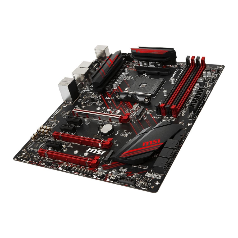
- Manuals
- Brands
- MSI Manuals
- Motherboard
- X470 GAMING PLUS
- User manual
-
Contents
-
Table of Contents
-
Troubleshooting
-
Bookmarks
Quick Links
Unpacking
X470 GAMING PLUS
Thank you for buying the MSI
motherboard. Check to make sure
®
your motherboard box contains the following items. If something is missing, contact
your dealer as soon as possible.
Motherboard User
Drivers & Utilities
Guide
Disc
Motherboard
M.2 Screw x2
I/O Shield
SATA Cable x2
Case Badge
SATA Cable Labels
1
Unpacking
Related Manuals for MSI X470 GAMING PLUS
Summary of Contents for MSI X470 GAMING PLUS
-
Page 1: Unpacking
Unpacking X470 GAMING PLUS Thank you for buying the MSI motherboard. Check to make sure ® your motherboard box contains the following items. If something is missing, contact your dealer as soon as possible. Motherboard User Drivers & Utilities Guide…
-
Page 2: Safety Information
Safety Information y The components included in this package are prone to damage from electrostatic discharge (ESD). Please adhere to the following instructions to ensure successful computer assembly. y Ensure that all components are securely connected. Loose connections may cause the computer to not recognize a component or fail to start.
-
Page 3: Quick Start
Quick Start Preparing Tools and Components AM4 CPU ® Thermal Paste CPU Fan DDR4 Memory Power Supply Unit Chassis SATA Hard Disk Drive Graphics Card SATA DVD Drive A Package of Screws Phillips Screwdriver Quick Start…
-
Page 4: Installing A Processor
Installing a Processor https://youtu.be/Xv89nhFk1vc CPU_FAN1 Quick Start…
-
Page 5
Important If you are installing the screw-type CPU heatsink, please follow the figure below to remove the retention module first and then install the heatsink. Quick Start… -
Page 6: Installing Ddr4 Memory
Installing DDR4 memory http://youtu.be/T03aDrJPyQs DIMMB2 DIMMB2 DIMMB1 DIMMA2 DIMMA2 DIMMA2 DIMMA1 Quick Start…
-
Page 7: Connecting The Front Panel Header
Connecting the Front Panel Header http://youtu.be/DPELIdVNZUI HDD LED + Power LED + HDD LED — Power LED — Reset Switch Power Switch Reset Switch Power Switch JFP1 Reserved No Pin JFP1 HDD LED — HDD LED HDD LED + POWER LED — POWER LED POWER LED + Quick Start…
-
Page 8: Installing The Motherboard
Installing the Motherboard Quick Start…
-
Page 9: Installing Sata Drives
Installing SATA Drives http://youtu.be/RZsMpqxythc Quick Start…
-
Page 10: Installing A Graphics Card
Installing a Graphics Card http://youtu.be/mG0GZpr9w_A Quick Start…
-
Page 11: Connecting Peripheral Devices
Connecting Peripheral Devices Quick Start…
-
Page 12: Connecting The Power Connectors
Connecting the Power Connectors http://youtu.be/gkDYyR_83I4 ATX_PWR1 CPU_PWR1 CPU_PWR2 Quick Start…
-
Page 13: Power On
Power On Quick Start…
-
Page 14: Table Of Contents
Contents Unpacking ………………….1 Safety Information ………………..2 Quick Start ………………….3 Preparing Tools and Components …………….3 Installing a Processor ………………… 4 Installing DDR4 memory ………………6 Connecting the Front Panel Header …………… 7 Installing the Motherboard ………………8 Installing SATA Drives…………………
-
Page 15
CLR_CMOS1: Clear CMOS Button ……………. 40 BIOS Setup ………………….41 Entering BIOS Setup ………………… 41 Resetting BIOS …………………. 42 Updating BIOS ………………….. 42 System Status ………………….. 43 Advanced ………………….. 44 OC …………………….. 50 M-FLASH ………………….55 Security ……………………. 56 Boot ……………………58 Save &… -
Page 16
Contents… -
Page 17: Specifications
Supports ECC UDIMM memory * A-series/ Athlon™ processors support up to 2400 MHz. And the supporting frequency of memory varies with installed processor. Please refer www.msi.com for more information on compatible memory. y 2x PCIe 3.0 x16 slots (PCIE_1, PCIE_4) ƒ…
-
Page 18
Continued from previous page 1x Realtek 8111H Gigabit LAN controller ® y 6x SATA 6Gb/s ports (from AMD X470 Chipset) ® y 2x M.2 ports (Key M)* ƒ M2_1 slot (from AMD processor) supports PCIe 3.0 ® x4 (1st, 2nd and 3rd Gen AMD Ryzen™/ Ryzen™ with Radeon™… -
Page 19
Continued from previous page y 1x PS/2 keyboard/ mouse combo port y 2x USB 2.0 Type-A ports y 1x DVI-D port y 1x HDMI™ 1.4 port Back Panel y 4x USB 3.1 Gen1 Type-A ports Connectors y 1x LAN (RJ45) port y 2x USB 3.1 Gen2 Type-A ports y 5x OFC audio jacks y 1x Optical S/PDIF OUT connector… -
Page 20
GAMING APP Software y RAMDISK y X-BOOST y SMART TOOL y Nahimic Audio y Open Broadcaster Software (OBS) y Norton™ Internet Security Solution y Google Chrome™, Google Toolbar, Google Drive y CPU-Z MSI GAMING Continued on next page Specifications… -
Page 21
Continued from previous page y Audio ƒ Audio Boost ƒ Voice Boost ƒ Nahimic 2.5 y Storage ƒ Turbo M.2 y Fan ƒ Pump Fan ƒ Smart Fan Control y LED ƒ Mystic Light ƒ Mystic Light Extension ƒ Mystic light SYNC ƒ… -
Page 22: Block Diagram
Block Diagram HDMI DVI-D 2 Channel DDR4 Memory 1 x M.2 PCI Express Bus PCIex4 4 x USB 3.1 Gen1 Realtek ALC892 Audio Jacks NV6795 Super I/O P/S2 Mouse / Keyboard PCIe x4 slot Switch PCIe x1 slot 1 x M.2 PCIe x1 slot Switch PCIe x1 slot…
-
Page 23: Rear I/O Panel
Rear I/O Panel Audio Ports USB 3.1 Gen1 PS/2 DVI-D USB 2.0 USB 3.1 Gen2 Optical S/PDIF-Out USB 3.1 Gen1 LAN Port LED Status Table Link/ Activity LED Speed LED Status Description Status Description No link 10 Mbps connection Yellow Linked Green 100 Mbps connection…
-
Page 24: Realtek Hd Audio Manager
Realtek HD Audio Manager After installing the Realtek HD Audio driver, the Realtek HD Audio Manager icon will appear in the system tray. Double click on the icon to launch. Device Selection Advanced Settings Jack Status Application Enhancement Main Volume Connector Settings Profiles…
-
Page 25
Audio jacks to headphone and microphone diagram Audio jacks to stereo speakers diagram AUDIO INPUT Audio jacks to 7.1-channel speakers diagram AUDIO INPUT Rear Front Side Center/ Subwoofer Rear I/O Panel… -
Page 26: Overview Of Components
Overview of Components DIMMB1 DIMMA2 DIMMB2 DIMMA1 SYS_FAN1 CPU_PWR2 CPU_FAN1 CPU_PWR1 CPU Socket PUMP_FAN1 SYS_FAN3 ATX_PWR1 JRGB2 SYS_FAN4 M2_1 PCI_E1 JUSB4 PCI_E2 JTPM1 PCI_E3 SATA▼5▲6 JCI1 PCI_E4 SATA▼3▲4 JBAT1 PCI_E5 SATA▼1▲2 M2_2 PCI_E6 JFP2 JAUD1 JCOM1 JRGB1 JLPT1 JFP1 SYS_FAN2 JUSB3 Clear CMOS JUSB2…
-
Page 27
Component Contents Port Name Port Type Page CLR_CMOS1 Clear CMOS Button CPU_FAN1, PUMP_FAN1, Fan Connectors SYS_FAN1~4 CPU_PWR1, CPU_PWR2, Power Connectors ATX_PWR1 CPU Socket AM4 CPU Socket DIMMA1, DIMMA2, DIMM Slots DIMMB1, DIMMB2 JAUD1 Front Audio Connector JBAT1 Clear CMOS (Reset BIOS) Jumper JCI1 Chassis Intrusion Connector JCOM1… -
Page 28: Cpu Socket
This motherboard is designed to support overclocking. Before attempting to overclock, please make sure that all other system components can tolerate overclocking. Any attempt to operate beyond product specifications is not recommended. MSI does not guarantee the damages or risks caused by inadequate ®…
-
Page 29: Dimm Slots
Due to AM4 CPU/memory controller official specification limitation, the frequency of memory modules may operate lower than the marked value under the default state. Please refer www.msi.com for more information on compatible memory. Overview of Components…
-
Page 30: Pci_E1~6: Pcie Expansion Slots
Important If you install a large and heavy graphics card, you need to use a tool such as MSI Gaming Series Graphics Card Bolster to support its weight to prevent deformation of the slot. For a single PCIe x16 expansion card installation with optimum performance, using the PCI_E1 slot is recommended.
-
Page 31
PCIe bandwidth table For Ryzen™ Desktop processors Slot Single 2-Way PCI_E1 (CPU) Gen 3.0 x 16* Gen 3.0 x 8* PCI_E2 (PCH) Gen 2.0 x 1 Gen 2.0 x 1 PCI_E3 (PCH) Gen 2.0 x 1 Gen 2.0 x 1 ─… -
Page 32: M2_1~2: M.2 Slots (Key M)
M2_1~2: M.2 Slots (Key M) Important SATA1 port will be unavailable when installing SATA M.2 SSD in M2_2 slot. PCI_E6 slot will be unavailable when installing PCIe M.2 SSD in M2_2 slot. M2_1 M2_1 slot only supports PCIe mode. M2_2 Video Demonstration Watch the video to learn how to Install M.2 SSD.
-
Page 33: Sata1~6: Sata 6Gb/S Connectors
SATA1~6: SATA 6Gb/s Connectors These connectors are SATA 6Gb/s interface ports. Each connector can connect to one SATA device. SATA6 SATA5 SATA4 SATA3 SATA2 SATA1 Important SATA1 port will be unavailable when installing SATA M.2 SSD in M2_2 slot. Please do not fold the SATA cable at a 90-degree angle. Data loss may result during transmission otherwise.
-
Page 34: Cpu_Pwr1, Cpu_Pwr2, Atx_Pwr1: Power Connectors
CPU_PWR1, CPU_PWR2, ATX_PWR1: Power Connectors These connectors allow you to connect an ATX power supply. CPU_PWR1 Ground +12V Ground +12V Ground +12V Ground +12V CPU_PWR2 Ground +12V Ground +12V +3.3V +3.3V +3.3V -12V Ground Ground PS-ON# Ground Ground Ground ATX_PWR1 Ground Ground PWR OK…
-
Page 35: Jusb1~2: Usb 2.0 Connectors
JUSB1~2: USB 2.0 Connectors These connectors allow you to connect USB 2.0 ports on the front panel. USB0- USB1- USB0+ USB1+ Ground Ground No Pin Important Note that the VCC and Ground pins must be connected correctly to avoid possible damage.
-
Page 36: Cpu_Fan1, Pump_Fan1, Sys_Fan1~4: Fan Connectors
CPU_FAN1, PUMP_FAN1, SYS_FAN1~4: Fan Connectors Fan connectors can be classified as PWM (Pulse Width Modulation) Mode or DC Mode. PWM Mode fan connectors provide constant 12V output and adjust fan speed with speed control signal. DC Mode fan connectors control fan speed by changing voltage.
-
Page 37: Jaud1: Front Audio Connector
JAUD1: Front Audio Connector This connector allows you to connect audio jacks on the front panel. MIC L Ground MIC R Head Phone R MIC Detection SENSE_SEND No Pin Head Phone L Head Phone Detection JCI1: Chassis Intrusion Connector This connector allows you to connect the chassis intrusion switch cable. Normal Trigger the chassis intrusion event…
-
Page 38: Jfp1, Jfp2: Front Panel Connectors
JFP1, JFP2: Front Panel Connectors These connectors connect to the switches and LEDs on the front panel. JFP1 HDD LED + Power LED + HDD LED — Power LED — Reset Switch Power Switch Reset Switch Power Switch Reserved No Pin Speaker — Buzzer + JFP2…
-
Page 39: Jcom1: Serial Port Connector
Please keeping the LED strip shorter than 2 meters to prevent dimming. Always turn off the power supply and unplug the power cord from the power outlet before installing or removing the RGB LED strip. Please use MSI’ s software to control the extended LED strip. Overview of Components…
-
Page 40: Jbat1: Clear Cmos (Reset Bios) Jumper
JBAT1: Clear CMOS (Reset BIOS) Jumper There is CMOS memory onboard that is external powered from a battery located on the motherboard to save system configuration data. If you want to clear the system configuration, set the jumpers to clear the CMOS memory. Keep Data Clear CMOS/ Reset BIOS…
-
Page 41: Bios Setup
BIOS Setup The default settings offer the optimal performance for system stability in normal conditions. You should always keep the default settings to avoid possible system damage or failure booting unless you are familiar with BIOS. Important BIOS items are continuously update for better system performance. Therefore, the description may be slightly different from the latest BIOS and should be for reference only.
-
Page 42: Resetting Bios
Updating BIOS Updating BIOS with M-FLASH Before updating: Please download the latest BIOS file that matches your motherboard model from MSI website. And then save the BIOS file into the USB flash drive. Updating BIOS: 1. Insert the USB flash drive that contains the update file into the computer.
-
Page 43: System Status
System Status f System Language [English] Choose the BIOS default language. f System Date Sets the system date. Use tab key to switch between date elements. The format is <day> <month> <date> <year>. <day> Day of the week, from Sun to Sat, determined by BIOS. Read-only. <month>…
-
Page 44: Advanced
[Disabled] Disables this function. fPCI_E1 Lanes Configuration PCIe lanes configuration is for MSI M.2 Xpander / MSI M.2 Xpander-Z / Other M.2 PCIe storage card. The options in this item will vary with the installed processor. f ACPI Settings Sets ACPI parameters of onboard power LED behaviors. Press Enter to enter the sub- menu.
-
Page 45
fPower LED [Blinking] Sets shining behaviors of the onboard Power LED. [Dual Color] The power LED turns to another color to indicate the S3 state. [Blinking] The power LED blinks to indicate the S3 state. f Integrated Peripherals Sets integrated peripherals’ parameters, such as LAN, HDD, USB and audio. Press Enter to enter the sub-menu. -
Page 46
f Integrated Graphics Configuration (optional) Adjusts integrated graphics settings for optimum system. Press Enter to enter the sub-menu. fInitiate Graphic Adapter [PEG] (optional) Selects a graphics device as the primary boot device. [IGD] Integrated Graphics Display. [PEG] PCI-Express Graphics Device. fIntegrated Graphics [Auto] (optional) If set to Force, BIOS will enable the integrated graphics controller. -
Page 47
fParallel (LPT) Port Settings [Auto] Sets parallel port (LPT). If set to Auto, BIOS will optimize the IRQ automatically or you can set it manually. fDevice Mode [STD Printer Mode] Selects an operating mode for parallel port. [STD Printer Mode] Printer port mode [SPP] Standard Parallel Port mode… -
Page 48
fGOP Information Shows the onboard Graphics Output Protocol (GOP) information. Press Enter to enter the sub-menu. This sub-menu will appear when BIOS UEFI/CSM Mode sets to UEFI. fSecure Boot Sets the Windows secure boot to prevent the unauthorized accessing. Press Enter to enter the sub-menu. -
Page 49
fResume From S3/S4/S5 by PS/2 Keyboard [Disabled] Enables or disables the system wake up by PS/2 keyboard. [Any Key] Enables the system to be awakened from S3/ S4/ S5 state when activity of any key on PS/2 keyboard is detected. [Hot Key] Enables the system to be awakened from S3/ S4/ S5 state when activity of hot key on PS/2 keyboard is detected. -
Page 50
Important Overclocking your PC manually is only recommended for advanced users. Overclocking is not guaranteed, and if done improperly, it could void your warranty or severely damage your hardware. If you are unfamiliar with overclocking, we advise you to use GAME BOOST function for easy overclocking. -
Page 51
f DRAM Frequency [Auto] Sets the DRAM frequency. Please note the overclocking behavior is not guaranteed. f Adjusted DRAM Frequency Shows the adjusted DRAM frequency. Read-only. f Memory Try It ! [Disabled] It can improve memory compatibility or performance by choosing optimized memory preset. -
Page 52
fCPU NB/SoC Under Voltage Protection [Auto] Sets the voltage limit for NB/ SoC under-voltage protection. If set to Auto, BIOS will configure this setting automatically. Higher voltage provides less protection and may damage the system. fCPU NB/SoC Over Current Protection [Auto] Sets the current limit for CPU NB/ SoC over-current protection. -
Page 53
fSimultaneous Multi-Threading [Enabled] (optional) Enables/ disables the AMD Simultaneous Multi-Threading. This item appears when the installed CPU supports this technology. fOpcache Control [Auto] (optional) Enables/ disables Opcache. Opcache stores recent decode instruction to save the decoding time when the instruction is repeated. And it may increase the CPU performance and reduce the power consumption slightly. -
Page 54
fCPU VDD_SoC Current Optimization [Auto] (optional) Sets the currents of CPU VDD and SoC. If set to Auto, BIOS will configure this setting automatically. [Auto] This setting will be configured automatically by BIOS. [Custom Setting] Allows you to set the currents manually. BIOS Setup… -
Page 55: M-Flash
M-FLASH provides the way to update BIOS with a USB flash drive. Please download the latest BIOS file that matches your motherboard model from MSI website, save the BIOS file into your USB flash drive. And then follow the steps below to update BIOS.
-
Page 56: Security
Security f Administrator Password Sets administrator password for system security. User has full rights to change the BIOS items with administrator password. After setting the administrator password, the state of this item will show Installed. f User Password Sets User Password for system security. User has limited rights to change the BIOS items with user password.
-
Page 57
you can enter the setup and OS without authorization. f Trusted Computing Sets TPM (Trusted Platform Module) function. fSecurity Device Support [Disabled] Enables or disables the TPM function to build the endorsement key for accessing the system. fAMD fTPM switch [AMD CPU fTPM] Selects TPM device. -
Page 58: Boot
Boot The Boot Menu allows you to specify the priority of boot devices. f Full Screen Logo Display [Enabled] Enables or disables to show the full screen logo while system POST. [Enabled] Shows the logo in full screen. [Disabled] Shows the POST messages. f Bootup NumLock State [On] Select the keyboard NumLock state upon bootup.
-
Page 59: Save & Exit
Save & Exit f Discard Changes and Exit Exit BIOS setup without saving any change. f Save Changes and Reboot Save all changes and reboot the system. f Save Changes Save current changes. f Discard Changes Discard all changes and restore to the previous values. f Restore Defaults Restore or load all default values.
-
Page 60: Software Description
7. Follow the instructions on the screen to install Windows ® Installing Drivers 1. Start up your computer in Windows ® 2. Insert MSI Driver Disc into your optical drive. ® 3. The installer will automatically appear and it will find and list all necessary drivers.
-
Page 61: App Manager
Motherboard Information — shows the model name of motherboard. y Total Install/ Update — click on this tab to update/ install all the applications. Important Please note that, once you uninstall the APP MANAGER, all the MSI applications and software will be uninstalled simultaneously. Software Description…
-
Page 62: Live Update 6
LIVE UPDATE 6 LIVE UPDATE 6 is an application for the MSI system to scan and download the latest ® drivers, BIOS and utilities. With LIVE UPDATE 6, you don’ t need to search the drivers on websites, and don’ t need to know the models of motherboard and graphics cards.
-
Page 63
1. Select the Live Update tab. 2. Choose Automatic scan, system will automatically scan all the items and search for the latest update files. Or you can choose Manual scan and select the items you wish to scan. 3. Click the Scan button at the bottom. It may take several moments to complete the process. -
Page 64: Command Center
COMMAND CENTER COMMAND CENTER is an user-friendly software and exclusively developed by MSI, helping users to adjust system settings and monitor status under OS. With the help of COMMAND CENTER, making it possible to achieve easier and efficient monitoring process and adjustments than that under BIOS. In addition, the COMMAND CENTER can be a server for mobile remote control application.
-
Page 65
CPU Fan CPU Fan control panel provides Smart mode and Manual Mode. You can switch the control mode by clicking the Smart Mode and Manual Mode buttons on the top of the CPU Fan control panel. y Manual Mode — allows you to manually control the CPU fan speed by percentage. -
Page 66
Option Buttons — Advanced When click the Advanced button, The Voltage, Fan and DRAM icons will appear. y Voltage — allows you to adjust advanced voltage values of CPU and chipset. y Fan — allows you to control the system fans speed. y DRAM — shows the current Advanced DRAM parameters, and allows you to change the settings by selecting values from the drop-down menu on the right hand side. -
Page 67
7. Find the IP address on the SoftAP Management Setting area, and enter the IP address on your MSI COMMAND CENTER APP to link your system. ® 8. Press Refresh on the MSI COMMAND CENTER APP to verify that monitoring and ® OC functions are working properly. -
Page 68: Gaming App
3. Connect your android device and motherboard to the same local area network. 4. Run MSI GAMING APP APP on your android device. ® 5. Press the Remote Control Setting icon on the MSI GAMING APP APP to find the ® paired device Name you set in the Remote Control Setting panel.
-
Page 69
OSD Setting Panel Use the OSD setting panel to specify information within on-screen display (OSD). y Apply Button — applies above settings to OSD. Eye Rest Eye Rest allows you to optimize the display on your monitor. y EyeRest — reduces blue-light of your LED backlit screen, in order to protect your eyes. -
Page 70
ƒ Login Keys — provides hotkey login function. ƒ MSI Smart Keys — allows you to define hotkeys for MSI Smart Keys. y Hotkey Manager — allows you to create, edit and delete hotkeys. y Current Hotkeys — shows all existing hotkeys. -
Page 71
Mouse Master Mouse Master provides mouse macro function. You can also use it to change DPI of your mouse. DPI Setting Delay Time Default Button Macro Hot Key DPI Hot Key Mouse Action Action List Test Area Edit Buttons Clear Button Load Button Save Button y Delay Time — allows you to apply a delay time in mouse macro. -
Page 72
VR Ready It will optimize the performance of your system to ensure everything is VR Ready. VR ON/ OFF Applications y VR ON/ OFF -enables or disables VR settings. y Applications — appears when you turn on the VR support. It allows you to close some applications to optimize the system for better VR experience. -
Page 73: X-Boost
X-BOOST The MSI X-BOOST allows you to select the system performance mode to meet your current system environment or support faster storage access speed for your external storage or memory cards. Easy In Easy page, you can select one system performance mode to meet the current system environment.
-
Page 74
STORAGE BOOST — supports faster access speed of storage device. Important Please note that you can only select one mode at a time from Easy or Advance page as MSI X-BOOST function. The improved transfer rate/ access speed will vary with the USB/ storage device. Software Description… -
Page 75: Mystic Light
MYSTIC LIGHT MYSTIC LIGHT is an application allows you to control LED lights of MSI products. For some earlier products, you can go to product download page to download the applicable LED control software. Main Screen The Main screen is used to configure what devices need to be synchronized and LED light effect options.
-
Page 76
You can also change settings for single device. To do that, you have to click the sync bubble twice and make it turn gray as below. Then you go to DEVICE SETTING and click SETTING. click SETTING After that, the computer will open a different windows and you can modify LED there individually. -
Page 77
If you wish to customize multiple device at the same time, click the bubble until it turn red like below. Use the LIGHT EFFECT & COLOR section on the main menu to make change. Note: Currently only GTX 1080 Ti Lightning -/X/Z and GTX 1080 Ti Gaming -/X Trio supports Light Speed/Brightness and no device supports Direction. -
Page 78
Motherboard Screen The motherboard screen is used to configure the LED light effect of the motherboard. SYNC ALL Return Button Motherboard ON/ OFF ALL LED Name PROFILE Live Preview LED AREA Light Effect Apply Button Options Save Button Note: The motherboard picture and name may vary according to different models. y Return Button — returns to the main screen. -
Page 79: Mystic Light Party
This section allows you to control LED across different platform. The pre-requisite is that the platforms should all be connected within the same local network. Refer to device support list web page. https://www.msi.com/Landing/Mystic-Light-Party. PARTY Upon clicking PARTY, this window would pop out. On your master platform, click create a host group.
-
Page 80: Joining Group
The group has been created. The other computers in the same local network are able to join the group with MYSTIC LIGHT software. DELETE Group Button Control Group Button Invitation Status Indicator Group In/Out Status ƒ DELETE Group Button — deletes the group. ƒ…
-
Page 81: Group Control Panel
Group Control Panel If everything is set up properly, you can see your slave platform on master platform MYSTIC LIGHT PARTY window. APPLY button Light Effect Options Invite Button Color Selection Group Members Icon At the panel below, you may apply different LED settings and color to the selected platform.
-
Page 82: Inviting Member
y Invite Button — enters the INVITE screen. y Light Effect Options — allow you to customize lighting effect. Always on Breathe Random Flash Double flash Marquee Rainbow Sound beat y Color Selection — allows you to change color. Inviting Member Click the Invite button in the Group Control Panel to enter the INVITE screen.
-
Page 83: Smart Tool
SMART TOOL SMART TOOL is a convenient tool that can help you to create your Windows installation USB flash drive, and it can also create a super RAID. Main menu After installing and activating SMART TOOL, it will display a main menu for you to choose Smart Tool or SUPER RAID.
-
Page 84
SUPER RAID This utility allows you to create a super RAID in Windows system. To create a super RAID: 1. Use checkboxs to select the disks you want included in your RAID. 2. Choose Speed Up or Backup for RAID type. y Speed Up = RAID0 y Backup = RAID1 3. -
Page 85: Nahimic 2.5
HD Audio Recorder2 and Sound Tracker. Installation and Update Nahimic 2.5 is included in the audio driver. If you need to install it or update it, please use the Driver Disc with your motherboard or download the driver from MSI’ s official website. Audio Tab From this tab, you can access all of Nahimic 2.5’…
-
Page 86
˜ Music — expands the stereo for a wider sound stage. Each audio effect can be disabled by clicking on it. ƒ Reverb — increases the feeling of space by applying different types of reverbs corresponding to different room sizes. ƒ… -
Page 87
Microphone Tab From this tab, you can access all of Nahimic 2.5’ s microphone effects and settings. Microphone Loopback Device properties Display & Volume Microphone Effects Reset Button Mute On/Off Button y Display & Volume — displays the type of audio recording device currently being used as input, as well as its current volume. -
Page 88
Audio Launchpad effects Control page Properties y Audio Launchpad effects — allows streamers to use prerecorded sounds during a livestream. These sounds can also be heard by viewers. This tool will allow you to create your true audio identity. That way, your livestreams will be more personal and animated. -
Page 89
Sound Tracker The Sound Tracker is an FPS oriented feature that provides a visual indication localizing the source of the strongest sound while in a game. The Sound Tracker captions the 5.1 and 7.1 sound streams processed by your audio system, and is displayed in all applications and games using DirectX 9, 9c, 10 and 11. -
Page 90: Amd Raid Configuration
AMD RAID Configuration The following are the RAID levels supported by RAIDXpert2. RAID 0 (Striping) breaks the data into blocks which are written to separate hard drives. Spreading the hard drive I/O load across independent channels greatly improves I/O performance. RAID 1 (Mirroring) provides data redundancy by mirroring data between the hard drives and provides enhanced read performance.
-
Page 91: Initializing Disks
Initializing Disks New disks and legacy disks must be initialized before they can be used to create an AMD-RAID array. Initialization writes AMD-RAID configuration information (metadata) to a disk. Important If a disk is part of an AMD-RAID array, the disk cannot be selected for initialization. To initial the disk anyway, delete the AMD-RAID array.
-
Page 92: Creating Arrays
Creating Arrays Arrays can be created after the disks are initialized. Important For redundant arrays, the Create process is not started until after the operating system and AMD-RAID OS drivers have been installed and the system has booted to the operating system. However, the arrays are immediately available to use for either a bootable array or a data array.
-
Page 93: Deleting Arrays
Deleting Arrays Important Deleting an array permanently destroys all data that is on the array. This action cannot be undone and it is very unlikely that the data can be recovered. Do not delete the first array listed in the Arrays section, if it is the AMD-RAID bootable array.
-
Page 94: Installing Raid Driver
2. When prompted, insert the USB flash drive with AMD RAID Drivers and then click Browse. ƒ To make an AMD RAID Drivers USB flash drive. Insert the MSI Driver Disc into the optical drive. Copy all the contents in \StorageAMDPackagesDriversSBDrv 3.
-
Page 95: Troubleshooting
Troubleshooting Lost BIOS password Before sending the motherboard for RMA repair, try to go over troubleshooting y Clear the CMOS, but that will cause guide first to see if your got similar you to lose all customized settings in the symptoms as mentioned below.
-
Page 96
The point of contact for regulatory matters is MSI, recycling and disposing of their end-of-life products. MSI-NL Eindhoven 5706 5692 ER Son. y Visit the MSI website and locate a nearby distributor B급 기기 (가정용 방송통신기자재) for further recycling information. -
Page 97
MSI will comply with the product take entregar a una empresa autorizada para la recogida de back requirements at the end of life of MSI-branded estos residuos. -
Page 98
MSI si adeguerà a tale Direttiva ritirando tutti i prodotti marchiati MSI che sono stati venduti all’interno dell’Unione Europea alla fine del loro ciclo di vita. -
Page 99
Micro-Star Int’ l Co., Ltd. All other marks and names mentioned may be trademarks of their respective owners. No warranty as to accuracy or completeness is expressed or implied. MSI reserves the right to make changes to this document without prior notice. Technical Support…

I
Quick Start
Quick Start
Thank you for purchasing the MSI
®
X470 GAMING PLUS MAX
motherboard. This Quick Start section provides demonstration
diagrams about how to install your computer. Some of the
installations also provide video demonstrations. Please link to the
URL to watch it with the web browser on your phone or tablet. You
may have even link to the URL by scanning the QR code.
Kurzanleitung
Danke, dass Sie das MSI
®
X470 GAMING PLUS MAX Motherboard
gewählt haben. Dieser Abschnitt der Kurzanleitung bietet eine Demo
zur Installation Ihres Computers. Manche Installationen bieten
auch die Videodemonstrationen. Klicken Sie auf die URL, um diese
Videoanleitung mit Ihrem Browser auf Ihrem Handy oder Table
anzusehen. Oder scannen Sie auch den QR Code mit Ihrem Handy,
um die URL zu öffnen.
Présentation rapide
Merci d’avoir choisi la carte mère MSI
®
X470 GAMING PLUS MAX.
Ce manuel fournit une rapide présentation avec des illustrations
explicatives qui vous aideront à assembler votre ordinateur. Des
tutoriels vidéo sont disponibles pour certaines étapes. Cliquez sur
le lien fourni pour regarder la vidéo sur votre téléphone ou votre
tablette. Vous pouvez également accéder au lien en scannant le QR
code qui lui est associé.
Быстрый старт
Благодарим вас за покупку материнской платы MSI
®
X470
GAMING PLUS MAX. В этом разделе представлена информация,
которая поможет вам при сборке комьютера. Для некоторых
этапов сборки имеются видеоинструкции. Для просмотра
видео, необходимо открыть соответствующую ссылку в
веб—браузере на вашем телефоне или планшете. Вы также
можете выполнить переход по ссылке, путем сканирования
QR-кода.

II
Quick Start
Installing a Processor/ Installation des Prozessors/ Installer un
processeur/ Установка процессора
1
2
3
6
4
5
7
8
9
CPU_FAN1
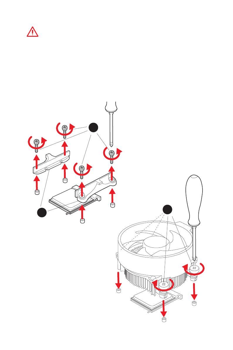
III
Quick Start
1
2
3
If you are installing the screw-type CPU heatsink, please follow the figure below
to remove the retention module first and then install the heatsink.
Wenn Sie einen CPU-Kühler mit Schraubenbefestigung einsetzen, folgen Sie bitte
den Anweisungen unten um das Retention-Modul zu entfernen und den Kühler zu
installieren.
Si vous voulez installer un ventirad pour processeur à vis, veuillez suivre les
instructions ci-dessous pour d’abord retirer le module de rétention puis installer le
ventirad.
В случае установки процессорного кулера с системой крепления на винтах,
следуйте указаниям на рисунке ниже для снятия пластикового модуля
крепления. Затем установите кулер.
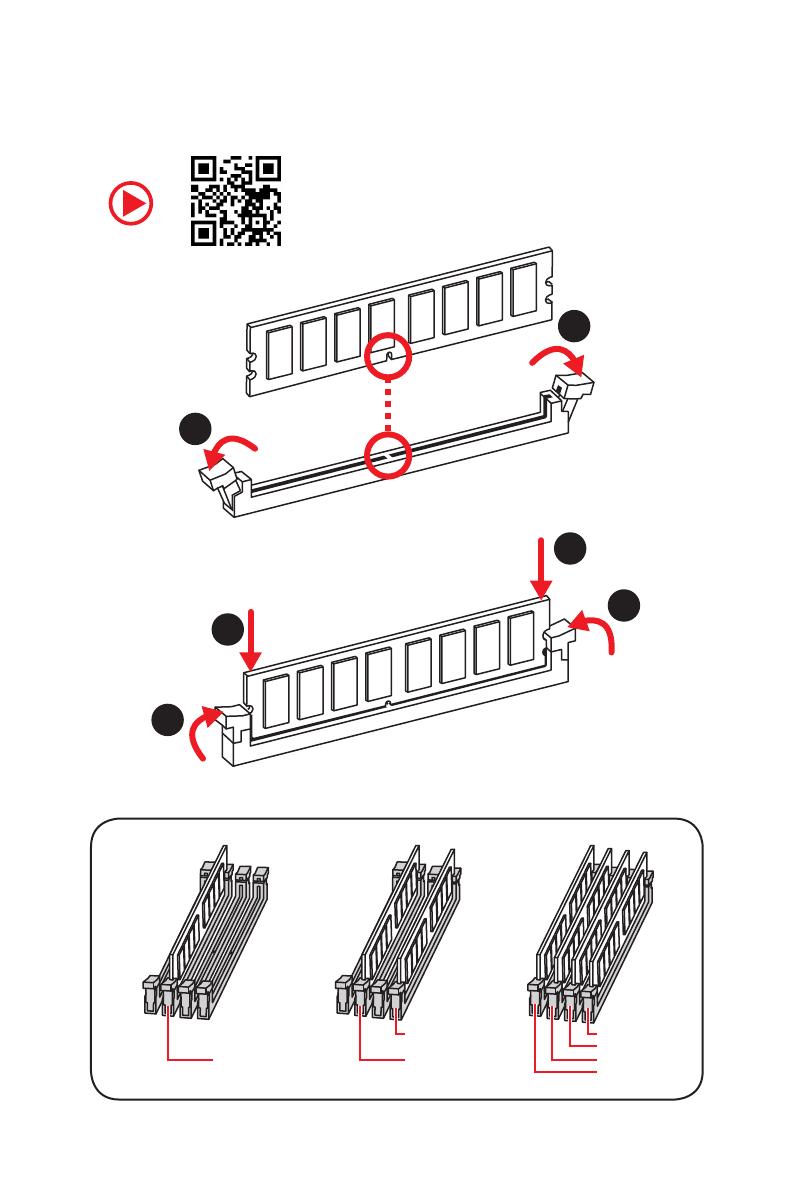
IV
Quick Start
Installing DDR4 memory/ Installation des DDR4-Speichers/
Installer une mémoire DDR4/ Установка памяти DDR4
DIMMB2 DIMMB2
DIMMB1
DIMMA2 DIMMA2 DIMMA2
DIMMA1
1
1
2
2
3
3
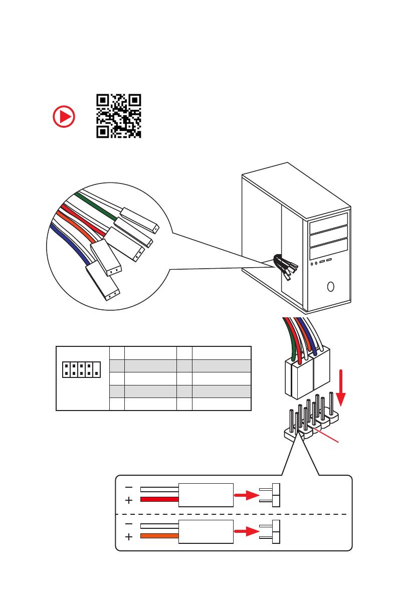
V
Quick Start
RESET SW
POWER SW
POWER LED+
POWER LED-
HDD LED
HDD LED
RESET SW
JFP1
HDD LED
HDD LED —
HDD LED +
POWER LED —
POWER LED +
POWER LED
Connecting the Front Panel Header/ Anschließen der
Frontpanel-Stiftleiste/ Connecter un connecteur du panneau
avant/ Подключение разъемов передней панели
1
2 10
9
JFP1
1 HDD LED + 2 Power LED +
3 HDD LED — 4 Power LED —
5 Reset Switch 6 Power Switch
7 Reset Switch 8 Power Switch
9 Reserved 10 No Pin

VII
Quick Start
1
2
3
4
5
Installing SATA Drives/ Installation der SATA-Laufwerke/
Installer le disque dur SATA/ Установка дисков SATA
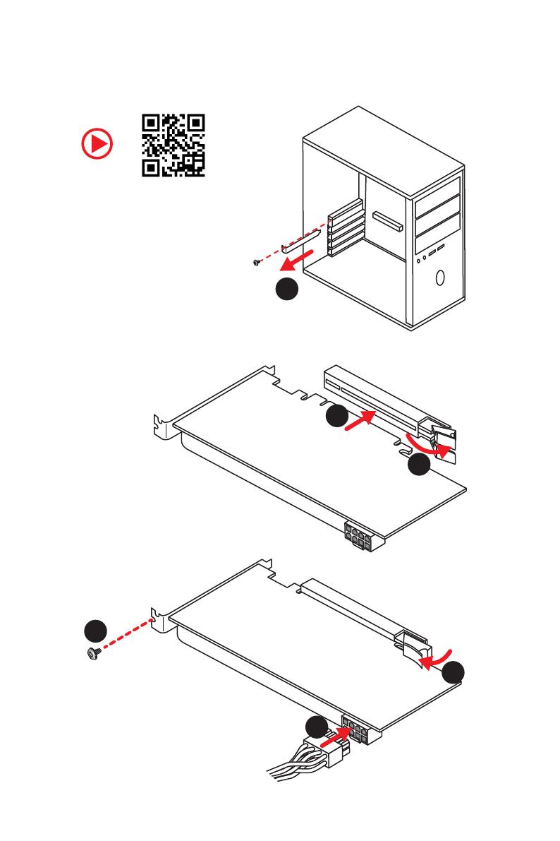
VIII
Quick Start
1
2
3
4
5
6
Installing a Graphics Card/ Einbau der Grafikkarte/ Installer
une carte graphique/ Установка дискретной видеокарты

IX
Quick Start
Connecting Peripheral Devices/ Peripheriegeräte/
Connecter un périphérique anschliessen/ Подключение
периферийных устройств
Integrated Graphics Processing Unit (iGPU)

X
Quick Start
Connecting the Power Connectors/ Stromanschlüsse
anschliessen/ Connecter les câbles du module d’alimentation/
Подключение разъемов питания
ATX_PWR1
CPU_PWR1

XII
Quick Start
NOTE

4
Specifications
Continued from previous page
Multi-GPU
y 1st, 2nd and 3rd Gen AMD Ryzen™ Processors
Supports 3-Way AMD
®
CrossFire™ Technology
y Ryzen™ with Radeon™ Vega Graphics and 2nd Gen AMD
Ryzen™ with Radeon™ Graphics/ Athlon™ with Radeon™
Vega Graphics Processors
Supports 2-Way AMD
®
CrossFire™ Technology
LAN 1x Realtek
®
8111H Gigabit LAN controller
Storage
y 6x SATA 6Gb/s ports (from AMD
®
X470 Chipset)
y 2x M.2 ports (Key M)*
M2_1 slot (from AMD
®
processor) supports PCIe
3.0×4 (1st, 2nd and 3rd Gen AMD Ryzen™/ Ryzen™ with
Radeon™ Vega Graphics and 2nd Gen AMD Ryzen™ with
Radeon™ Graphics Processors) or PCIe 3.0×2 (Athlon™
with Radeon™ Vega Graphics Processors) 2242/ 2260
/2280/ 22110 storage devices
M2_2 slot (from AMD
®
X470 Chipset) supports PCIe 2.0
x4 and SATA 6Gb/s 2242/ 2260 /2280 storage devices
* SATA1 port will be unavailable when installing SATA M.2 SSD in M2_2 slot.
* PCI_E6 slot will be unavailable when installing PCIe M.2 SSD in M2_2 slot.
RAID
AMD
®
X470 Chipset
y Supports RAID 0, RAID 1 and RAID 10 for SATA storage
devices
USB
y ASMedia
®
ASM1143 Chipset
2x USB 3.2 Gen2 (SuperSpeed USB 10Gbps) Type-A
ports on the back panel
y AMD
®
X470 Chipset
4x USB 3.2 Gen1 (SuperSpeed USB) ports through the
internal USB connectors
6x USB 2.0 (High-speed USB) ports (2 Type-A ports on
the back panel, 4 ports available through the internal
USB connectors)
y AMD
®
CPU
4x USB 3.2 Gen1 (SuperSpeed USB) Type-A ports on the
back panel
Continued on next page

6
Specifications
Continued from previous page
I/O Controller NUVOTON NCT6795D Controller Chip
Hardware Monitor
y CPU/System temperature detection
y CPU/System fan speed detection
y CPU/System fan speed control
Form Factor
y ATX Form Factor
y 12 in. x 9.6 in. (30.5 cm x 24.4 cm)
BIOS Features
y 1x 256 Mb flash
y UEFI AMI BIOS
y ACPI 6.1, SM BIOS 2.8
y Multi-language
Software
y Drivers
y APP MANAGER
y COMMAND CENTER
y LIVE UPDATE 6
y MYSTIC LIGHT
y SUPER CHARGER
y GAMING APP
y RAMDISK
y X-BOOST
y SMART TOOL
y Nahimic Audio
y Open Broadcaster Software (OBS)
y Norton™ Internet Security Solution
y Google Chrome™, Google Toolbar, Google Drive
y CPU-Z MSI GAMING
Continued on next page
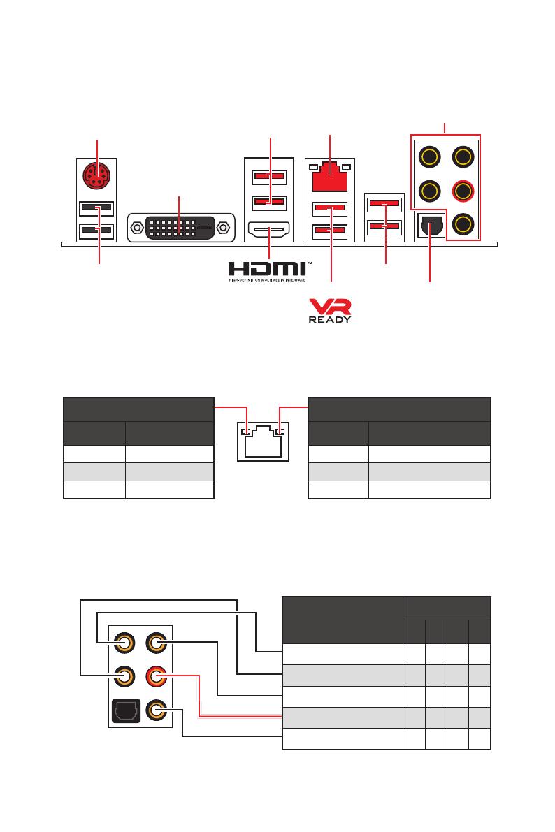
8
Rear I/O Panel
Audio Ports Configuration
Audio Ports
Channel
2 4 6 8
Center/ Subwoofer Out ● ●
Rear Speaker Out ● ● ●
Line-In/ Side Speaker Out ●
Line-Out/ Front Speaker Out ● ● ● ●
Mic In
(●: connected, Blank: empty)
Rear I/O Panel
LAN
USB 2.0
PS/2
Audio Ports
Optical S/PDIF-Out
USB 3.2 Gen1
USB 3.2 Gen1
USB 3.2 Gen2
Link/ Activity LED
Status Description
Off No link
Yellow Linked
Blinking Data activity
Speed LED
Status Description
Off 10 Mbps connection
Green 100 Mbps connection
Orange 1 Gbps connection
LAN Port LED Status Table
DVI-D
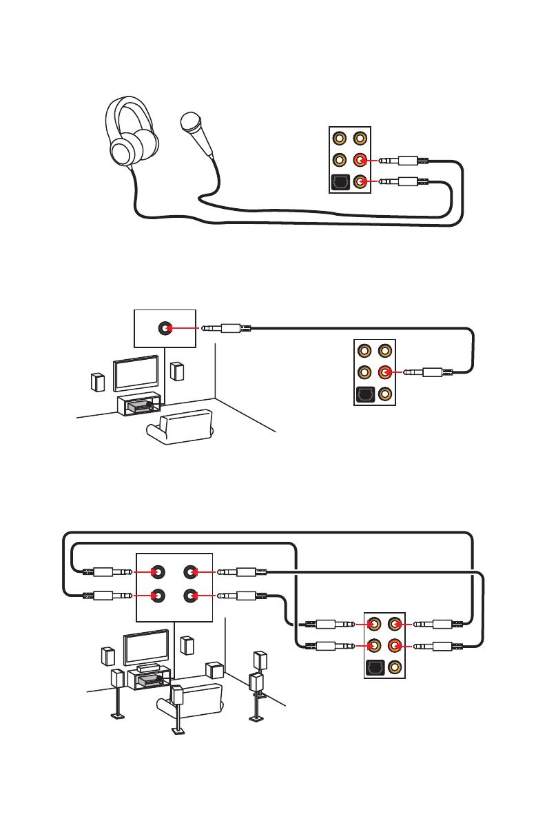
10
Rear I/O Panel
AUDIO INPUT
Rear Front
Side Center/
Subwoofer
Audio jacks to headphone and microphone diagram
Audio jacks to stereo speakers diagram
Audio jacks to 7.1-channel speakers diagram
AUDIO INPUT

11
Overview of Components
Overview of Components
SATA▼3▲4
SATA▼1▲2
SATA▼5▲6
CPU_FAN1
JRGB1
JRGB2
PUMP_FAN1
PCI_E1
PCI_E2
PCI_E3
PCI_E4
PCI_E5
PCI_E6
JTPM1
CPU Socket
CPU_PWR1
CPU_PWR2
JBAT1
M2_2
M2_1
DIMMA1
SYS_FAN1
DIMMA2
DIMMB1
DIMMB2
JLPT1
JUSB1
JUSB2
JFP2
JFP1
JAUD1
ATX_PWR1
SYS_FAN3
SYS_FAN4
SYS_FAN2
Clear CMOS
JCOM1
JUSB4
JCI1
JUSB3
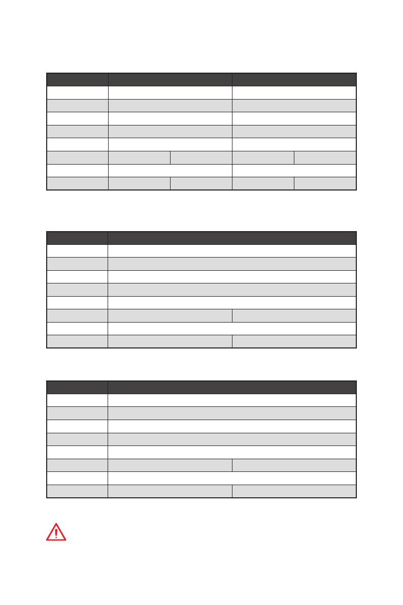
15
Overview of Components
PCIe bandwidth table
For 1st, 2nd and 3rd Gen AMD Ryzen™ Processors
Slot Single 2-Way
PCI_E1 (CPU) Gen 3.0 x 16* Gen 3.0 x 8*
PCI_E2 (PCH) Gen 2.0 x 1 Gen 2.0 x 1
PCI_E3 (PCH) Gen 2.0 x 1 Gen 2.0 x 1
PCI_E4 (CPU) ─ Gen 3.0 x 8*
PCI_E5 (PCH) Gen 2.0 x 1 Gen 2.0 x 1
PCI_E6 (PCH) Gen 2.0 x 4 ─ Gen 2.0 x 4 ─
M2_1 (CPU) Gen 3.0 x 4 Gen 3.0 x 4
M2_2 (PCH) ─ Gen 2.0 x 4 ─ Gen 2.0 x 4
(─: unavailable, *: graphics card)
For Ryzen™ with Radeon™ Vega Graphics and 2nd Gen AMD Ryzen™ with Radeon™
Graphics Processors
Slot Single
PCI_E1 (CPU) Gen 3.0 x 8*
PCI_E2 (PCH) Gen 2.0 x 1
PCI_E3 (PCH) Gen 2.0 x 1
PCI_E4 (CPU) ─
PCI_E5 (PCH) Gen 2.0 x 1
PCI_E6 (PCH) Gen 2.0 x 4 ─
M2_1 (CPU) Gen 3.0 x 4
M2_2 (PCH) ─ Gen 2.0 x 4
(─: unavailable, *: graphics card)
Athlon™ with Radeon™ Vega Graphics Processors
Slot Single
PCI_E1 (CPU) Gen 3.0 x 4*
PCI_E2 (PCH) Gen 2.0 x 1
PCI_E3 (PCH) Gen 2.0 x 1
PCI_E4 (CPU) ─
PCI_E5 (PCH) Gen 2.0 x 1
PCI_E6 (PCH) Gen 2.0 x 4 ─
M2_1 (CPU) Gen 3.0 x 2
M2_2 (PCH) ─ Gen 2.0 x 4
(─: unavailable, *: graphics card)
Important
PCI_E6 slot will be unavailable when installing PCIe M.2 SSD in M2_2 slot.
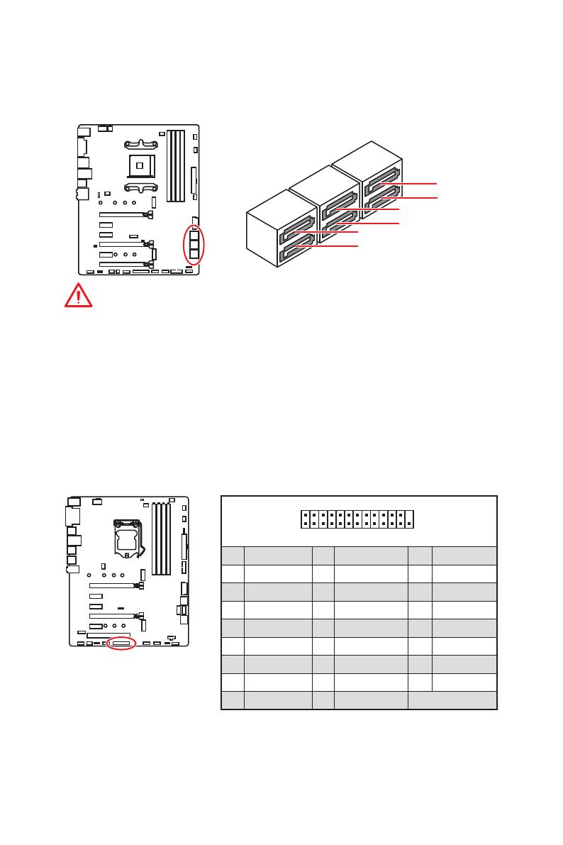
17
Overview of Components
SATA1~6: SATA 6Gb/s Connectors
These connectors are SATA 6Gb/s interface ports. Each connector can connect to one
SATA device.
SATA5
SATA3
SATA1
SATA6
SATA4
SATA2
Important
y
SATA1 port will be unavailable when installing SATA M.2 SSD in M2_2 slot.
y
Please do not fold the SATA cable at a 90-degree angle. Data loss may result during
transmission otherwise.
y
SATA cables have identical plugs on either sides of the cable. However, it is
recommended that the flat connector be connected to the motherboard for space
saving purposes.
1
2 26
25
1 RSTB# 2 AFD# 3 PRND0
4 ERR# 5 PRND1 6 PINIT#
7 PRND2 8 LPT_SLIN# 9 PRND3
10 Ground 11 PRND4 12 Ground
13 PRND5 14 Ground 15 PRND6
16 Ground 17 PRND7 18 Ground
19 ACK# 20 Ground 21 BUSY
22 Ground 23 PE 24 Ground
25 SLCT 26 No Pin
JLPT1: Parallel Port Connector
This connector allows you to connect the optional parallel port with bracket.
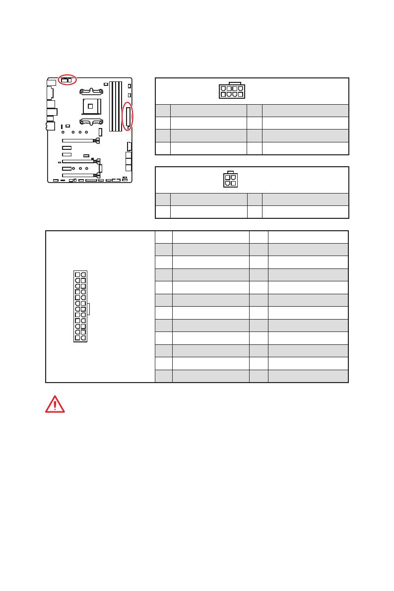
18
Overview of Components
24
131
12
ATX_PWR1
1 +3.3V 13 +3.3V
2 +3.3V 14 -12V
3 Ground 15 Ground
4 +5V 16 PS-ON#
5 Ground 17 Ground
6 +5V 18 Ground
7 Ground 19 Ground
8 PWR OK 20 Res
9 5VSB 21 +5V
10 +12V 22 +5V
11 +12V 23 +5V
12 +3.3V 24 Ground
5
4 1
8
CPU_PWR1
1 Ground 5 +12V
2 Ground 6 +12V
3 Ground 7 +12V
4 Ground 8 +12V
Important
Make sure that all the power cables are securely connected to a proper ATX power
supply to ensure stable operation of the motherboard.
CPU_PWR1, CPU_PWR2, ATX_PWR1: Power Connectors
These connectors allow you to connect an ATX power supply.
3
2 1
4
CPU_PWR2
1 Ground 3 +12V
2 Ground 4 +12V
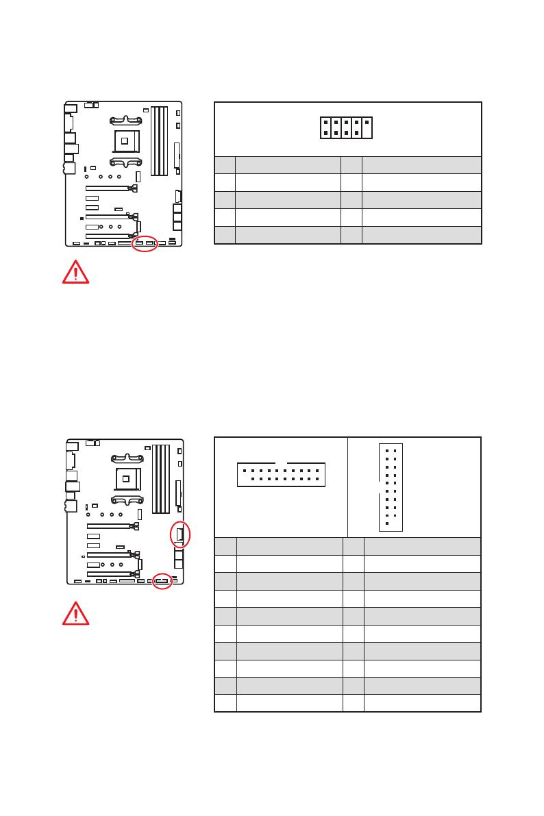
19
Overview of Components
JUSB3~4: USB 3.2 Gen1 Connectors
These connectors allow you to connect USB 3.2 Gen1 ports on the front panel.
Important
Note that the Power and
Ground pins must be
connected correctly to avoid
possible damage.
1 10
1120
JUSB3
1
10 11
20
JUSB4
1 Power 11 USB2.0+
2 USB3_RX_DN 12 USB2.0-
3 USB3_RX_DP 13 Ground
4 Ground 14 USB3_TX_C_DP
5 USB3_TX_C_DN 15 USB3_TX_C_DN
6 USB3_TX_C_DP 16 Ground
7 Ground 17 USB3_RX_DP
8 USB2.0- 18 USB3_RX_DN
9 USB2.0+ 19 Power
10 NC 20 No Pin
JUSB1~2: USB 2.0 Connectors
These connectors allow you to connect USB 2.0 ports on the front panel.
1
2 10
9
1 VCC 2 VCC
3 USB0- 4 USB1-
5 USB0+ 6 USB1+
7 Ground 8 Ground
9 No Pin 10 NC
Important
y
Note that the VCC and Ground pins must be connected correctly to avoid possible
damage.
y
In order to recharge your iPad,iPhone and iPod through USB ports, please install
MSI
®
SUPER CHARGER utility.
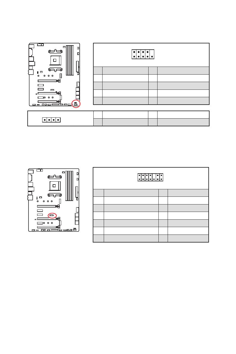
22
Overview of Components
1
2 14
13
1 LPC Clock 2 3V Standby power
3 LPC Reset 4 3.3V Power
5 LPC address & data pin0 6 Serial IRQ
7 LPC address & data pin1 8 5V Power
9 LPC address & data pin2 10 No Pin
11 LPC address & data pin3 12 Ground
13 LPC Frame 14 Ground
JTPM1: TPM Module Connector
This connector is for TPM (Trusted Platform Module). Please refer to the TPM security
platform manual for more details and usages.
JFP1, JFP2: Front Panel Connectors
These connectors connect to the switches and LEDs on the front panel.
1
2 10
9
JFP1
1 HDD LED + 2 Power LED +
3 HDD LED — 4 Power LED —
5 Reset Switch 6 Power Switch
7 Reset Switch 8 Power Switch
9 Reserved 10 No Pin
1
JFP2
1 Speaker — 2 Buzzer +
3 Buzzer — 4 Speaker +
Unpacking Thank you for buying the MSI® X470 GAMING PRO MAX motherboard. Check to make sure your motherboard box contains the following items. If something is missing, contact your dealer as soon as possible. Drivers & Utilities Disc Motherboard User Guide Motherboard M.2 Screw x2 I/O Shield SATA Cable x2 Case Badge SATA Cable Labels Unpacking 1 Safety Information y The components included in this package are prone to damage from electrostatic discharge (ESD). Please adhere to the following instructions to ensure successful computer assembly. y Ensure that all components are securely connected. Loose connections may cause the computer to not recognize a component or fail to start. y Hold the motherboard by the edges to avoid touching sensitive components. y It is recommended to wear an electrostatic discharge (ESD) wrist strap when handling the motherboard to prevent electrostatic damage. If an ESD wrist strap is not available, discharge yourself of static electricity by touching another metal object before handling the motherboard. y Store the motherboard in an electrostatic shielding container or on an anti-static pad whenever the motherboard is not installed. y Before turning on the computer, ensure that there are no loose screws or metal components on the motherboard or anywhere within the computer case. y Do not boot the computer before installation is completed. This could cause permanent damage to the components as well as injury to the user. y If you need help during any installation step, please consult a certified computer technician. y Always turn off the power supply and unplug the power cord from the power outlet before installing or removing any computer component. y Keep this user guide for future reference. y Keep this motherboard away from humidity. y Make sure that your electrical outlet provides the same voltage as is indicated on the PSU, before connecting the PSU to the electrical outlet. y Place the power cord such a way that people can not step on it. Do not place anything over the power cord. y All cautions and warnings on the motherboard should be noted. y If any of the following situations arises, get the motherboard checked by service personnel: Liquid has penetrated into the computer. The motherboard has been exposed to moisture. The motherboard does not work well or you can not get it work according to user guide. The motherboard has been dropped and damaged. The motherboard has obvious sign of breakage. y Do not leave this motherboard in an environment above 60°C (140°F), it may damage the motherboard. 2 Safety Information Quick Start Preparing Tools and Components AMD® AM4 CPU Thermal Paste CPU Fan DDR4 Memory Power Supply Unit Chassis SATA DVD Drive Phillips Screwdriver SATA Hard Disk Drive Graphics Card A Package of Screws Quick Start 3 Installing a Processor 1 3 2 5 4 6 8 9 7 4 Quick Start CPU_FAN1 Important If you are installing the screw-type CPU heatsink, please follow the figure below to remove the retention module first and then install the heatsink. 1 2 3 Quick Start 5 Installing DDR4 memory 1 1 2 3 2 3 DIMMB2 DIMMA2 6 Quick Start DIMMA2 DIMMB2 DIMMB1 DIMMA2 DIMMA1 Connecting the Front Panel Header - ED D+ LE ED DL 1 9 JFP1 1 HDD LED + 2 3 HDD LED - 4 Power LED + Power LED - 5 Reset Switch 6 Power Switch 7 Reset Switch 8 Power Switch 9 Reserved 10 No Pin RESET SW 10 HDD LED W TS SE RE PO HD SW ER PO W R WE RL WE PO 2 JFP1 HDD LED POWER LED HDD LED HDD LED + POWER LED POWER LED + Quick Start 7 Installing the Motherboard 1 2 8 Quick Start Installing SATA Drives 1 2 3 5 4 Quick Start 9 Installing a Graphics Card 1 3 2 5 4 6 10 Quick Start Connecting Peripheral Devices In te g ra te d Gr ap hi cs Pr oc es sin g Un it (iG PU ) Quick Start 11 Connecting the Power Connectors ATX_PWR1 CPU_PWR2 12 Quick Start CPU_PWR1 Power On 1 2 3 4 Quick Start 13 Contents Unpacking .............................................................................................................. 1 Safety Information ................................................................................................. 2 Quick Start ............................................................................................................. 3 Preparing Tools and Components .......................................................................... 3 Installing a Processor ............................................................................................. 4 Installing DDR4 memory ........................................................................................ 6 Connecting the Front Panel Header ....................................................................... 7 Installing the Motherboard ..................................................................................... 8 Installing SATA Drives............................................................................................. 9 Installing a Graphics Card .................................................................................... 10 Connecting Peripheral Devices ............................................................................ 11 Connecting the Power Connectors....................................................................... 12 Power On............................................................................................................... 13 Specifications....................................................................................................... 17 Block Diagram .................................................................................................... 22 Rear I/O Panel...................................................................................................... 23 LAN Port LED Status Table................................................................................... 23 Audio Ports Configuration .................................................................................... 23 Realtek HD Audio Manager .................................................................................. 24 Overview of Components .................................................................................... 26 CPU Socket ........................................................................................................... 28 DIMM Slots............................................................................................................ 29 PCI_E1~6: PCIe Expansion Slots .......................................................................... 30 M2_1~2: M.2 Slots (Key M) ................................................................................... 32 SATA1~6: SATA 6Gb/s Connectors ....................................................................... 33 JLPT1: Parallel Port Connector ........................................................................... 33 CPU_PWR1, CPU_PWR2, ATX_PWR1: Power Connectors .................................. 34 JUSB1~2: USB 2.0 Connectors ............................................................................. 35 JUSB3~4: USB 3.2 Gen1 Connectors ................................................................... 35 CPU_FAN1, PUMP_FAN1, SYS_FAN1~4: Fan Connectors ................................... 36 JAUD1: Front Audio Connector ............................................................................ 37 JCI1: Chassis Intrusion Connector ....................................................................... 37 JFP1, JFP2: Front Panel Connectors ................................................................... 38 JTPM1: TPM Module Connector ........................................................................... 38 JCOM1: Serial Port Connector ............................................................................. 39 JRGB1, JRGB2: RGB LED Connectors ................................................................. 39 JBAT1: Clear CMOS (Reset BIOS) Jumper ........................................................... 40 14 Contents CLR_CMOS1: Clear CMOS Button ........................................................................ 40 BIOS Setup ........................................................................................................... 41 Entering BIOS Setup ............................................................................................. 41 Resetting BIOS...................................................................................................... 42 Updating BIOS....................................................................................................... 42 EZ Mode ................................................................................................................ 43 Advanced Mode .................................................................................................... 45 SETTINGS.............................................................................................................. 46 Advanced ............................................................................................................... 46 Boot ....................................................................................................................... 51 Security ................................................................................................................. 52 Save & Exit ............................................................................................................ 54 OC.......................................................................................................................... 55 M-FLASH .............................................................................................................. 60 OC PROFILE .......................................................................................................... 61 HARDWARE MONITOR .......................................................................................... 62 A-XMP Operation .................................................................................................. 63 Software Description ........................................................................................... 64 Installing Windows® 10 ......................................................................................... 64 Installing Drivers .................................................................................................. 64 Installing Utilities ................................................................................................. 64 APP MANAGER ..................................................................................................... 65 LIVE UPDATE 6...................................................................................................... 66 COMMAND CENTER ............................................................................................. 68 GAMING APP ......................................................................................................... 72 X-BOOST ............................................................................................................... 77 MYSTIC LIGHT ....................................................................................................... 79 MYSTIC LIGHT PARTY ........................................................................................... 83 Joining Group ........................................................................................................ 84 Group Control Panel ............................................................................................. 85 Inviting Member .................................................................................................... 86 SMART TOOL......................................................................................................... 87 RAMDISK............................................................................................................... 89 Nahimic 2.5 ........................................................................................................... 90 RAID Configuration .............................................................................................. 95 Using AMD RAID Controller BIOS Configuration Utility ....................................... 95 Initialize Disks ...................................................................................................... 97 Create Arrays ........................................................................................................ 98 Delete Arrays ........................................................................................................ 99 Swap Arrays ........................................................................................................ 100 Contents 15 Manage Spares ................................................................................................... 101 Change the Controller Options ........................................................................... 102 Booting the system from an array...................................................................... 102 Pausing the boot sequence for warning messages ........................................... 102 Change the Staggered Spinup Count ................................................................. 103 Using UEFI to create a 2.2TB RAID .................................................................... 104 Installing RAID Driver ......................................................................................... 105 Troubleshooting ................................................................................................ 106 16 Contents Specifications CPU Supports 1st, 2nd and 3rd Gen AMD Ryzen™/ Ryzen™ with Radeon™ Vega Graphics and 2nd Gen AMD Ryzen™ with Radeon™ Graphics/ Athlon™ with Radeon™ Vega Graphics Desktop Processors for Socket AM4 Chipset AMD® X470 Chipset y 4x DDR4 memory slots, support up to 64GB Supports DDR4 1866/ 2133/ 2400/ 2667 Mhz by JEDEC, and 2667/ 2800/ 2933/ 3000/ 3066/ 3200/ 3466 Mhz by A-XMP OC MODE* Memory y Dual channel memory architecture y Supports non-ECC UDIMM memory y Supports ECC UDIMM memory * Athlon™ with Radeon™ Vega Graphics processors support up to 2400 MHz. And the supporting frequency of memory varies with installed processor. Please refer www.msi.com for more information on compatible memory. y 2x PCIe 3.0 x16 slots (PCIE_1, PCIE_4) 1st, 2nd and 3rd Gen AMD Ryzen™ Processors support x16/x0, x8/x8 mode Expansion Slots Ryzen™ with Radeon™ Vega Graphics and 2nd Gen AMD Ryzen™ with Radeon™ Graphics Processors support x8/ x0 mode Athlon™ with Radeon™ Vega Graphics Processors support x4/x0 mode y 1x PCIe 2.0 x16 slot (PCIE_6, supports x4 mode)* y 3x PCIe 2.0 x1 slots * PCI_E6 slot will be unavailable when installing M.2 PCIe SSD in M2_2 slot. y 1x DVI-D port, supports a maximum resolution of 1920x1200@60Hz* Onboard Graphics y 1x HDMI™ port 1.4, supports a maximum resolution of 4096x2160@30Hz* * Only support when using Radeon™ Vega Graphics and 2nd Gen AMD Ryzen™ with Radeon™ Graphics/ Athlon™ with Radeon™ Vega Graphics Processors * Maximum shared memory of 2048 MB Continued on next page Specifications 17 Continued from previous page y 1st, 2nd and 3rd Gen AMD Ryzen™ Processors Supports 3-Way AMD® CrossFire™ Technology Multi-GPU y Ryzen™ with Radeon™ Vega Graphics and 2nd Gen AMD Ryzen™ with Radeon™ Graphics/ Athlon™ with Radeon™ Vega Graphics Processors Supports 2-Way AMD® CrossFire™ Technology LAN 1x Realtek® 8111H Gigabit LAN controller y 6x SATA 6Gb/s ports (from AMD® X470 Chipset) y 2x M.2 ports (Key M)* Storage M2_1 slot (from AMD® processor) supports PCIe 3.0x4 (1st, 2nd and 3rd Gen AMD Ryzen™/ Ryzen™ with Radeon™ Vega Graphics and 2nd Gen AMD Ryzen™ with Radeon™ Graphics Processors) or PCIe 3.0x2 (Athlon™ with Radeon™ Vega Graphics Processors) 2242/ 2260 /2280/ 22110 storage devices M2_2 slot (from AMD® X470 Chipset) supports PCIe 2.0 x4 and SATA 6Gb/s 2242/ 2260 /2280 storage devices * SATA1 port will be unavailable when installing SATA M.2 SSD in M2_2 slot. * PCI_E6 slot will be unavailable when installing PCIe M.2 SSD in M2_2 slot. RAID AMD® X470 Chipset y Supports RAID 0, RAID 1 and RAID 10 for SATA storage devices y ASMedia® ASM1143 Chipset 2x USB 3.2 Gen2 (SuperSpeed USB 10Gbps) Type-A ports on the back panel y AMD® X470 Chipset USB 4x USB 3.2 Gen1 (SuperSpeed USB) ports through the internal USB connectors 6x USB 2.0 (High-speed USB) ports (2 Type-A ports on the back panel, 4 ports available through the internal USB connectors) y AMD® CPU 4x USB 3.2 Gen1 (SuperSpeed USB) Type-A ports on the back panel Continued on next page 18 Specifications Continued from previous page y Realtek® ALC892 Codec Audio y 7.1-Channel High Definition Audio y Supports S/PDIF output y 1x PS/2 keyboard/ mouse combo port y 2x USB 2.0 Type-A ports y 1x DVI-D port Back Panel Connectors y 1x HDMI™ 1.4 port y 4x USB 3.2 Gen1 Type-A ports y 1x LAN (RJ45) port y 2x USB 3.2 Gen2 Type-A ports y 5x OFC audio jacks y 1x Optical S/PDIF OUT connector y 1x 24-pin ATX main power connector y 1x 8-pin ATX 12V power connector y 1x 4-pin ATX 12V power connector y 6x SATA 6Gb/s connectors y 2x USB 2.0 connectors (support additional 4 USB 2.0 ports) y 2x USB 3.2 Gen1 connectors (support additional 4 USB 3.2 Gen1 ports) y 1x 4-pin CPU fan connector y 1x 4-pin PUMP fan connector (supports up to 2A) Internal Connectors y 4x 4-pin system fan connectors y 1x Serial port connector y 1x Parallel port connector y 2x 5050 RGB LED strip 12V connectors y 1x TPM module connector y 1x Front panel audio connector y 2x System panel connectors y 1x Chassis Intrusion connector y 1x Clear CMOS jumper y 1x Clear CMOS button Continued on next page Specifications 19 Continued from previous page I/O Controller NUVOTON NCT6795D Controller Chip y CPU/System temperature detection Hardware Monitor y CPU/System fan speed detection y CPU/System fan speed control Form Factor y ATX Form Factor y 12 in. x 9.6 in. (30.5 cm x 24.4 cm) y 1x 256 Mb flash BIOS Features y UEFI AMI BIOS y ACPI 6.1, SM BIOS 2.8 y Multi-language y Drivers y APP MANAGER y COMMAND CENTER y LIVE UPDATE 6 y MYSTIC LIGHT y SUPER CHARGER y GAMING APP Software y RAMDISK y X-BOOST y SMART TOOL y Nahimic Audio y Open Broadcaster Software (OBS) y Norton™ Internet Security Solution y Google Chrome™, Google Toolbar, Google Drive y CPU-Z MSI GAMING Continued on next page 20 Specifications Continued from previous page y Audio Audio Boost Voice Boost Nahimic 2.5 y Storage Turbo M.2 y Fan Pump Fan Smart Fan Control y LED Mystic Light Mystic Light Extension Mystic light SYNC EZ DEBUG LED y Protection Special Features PCI-E Steel Armor y Performance Multi GPU-CrossFire Technology DDR4 Boost GAME Boost X-Boost A-XMP y Stability 7000+ Quality Test y VR VR Ready y Gamer Experience RAMDisk y BIOS Click BIOS 5 y Certification GAMING Certified Specifications 21 Block Diagram HDMI DVI-D 2 Channel DDR4 Memory CPU 1 x M.2 PCI Express Bus PCIex4 4 x USB 3.2 Gen1 Realtek ALC892 Audio Jacks NV6795 Super I/O P/S2 Mouse / Keyboard PCIe x4 slot x1 Switch x1 1 x M.2 6 x SATA 6Gb/s 4 x USB 3.2 Gen1 PCI Express Bus Switch x1 X470 ASMEDIA ASM1143 6 x USB 2.0 RTL8111H 22 Block Diagram PCIe x1 slot PCIe x1 slot PCIe x1 slot 2 x USB 3.2 Gen2 Rear I/O Panel USB 3.2 Gen1 PS/2 Audio Ports LAN DVI-D USB 2.0 USB 3.2 Gen2 Optical S/PDIF-Out USB 3.2 Gen1 LAN Port LED Status Table Link/ Activity LED Speed LED Status Description Status Description Off No link Off 10 Mbps connection Yellow Linked Green 100 Mbps connection Blinking Data activity Orange 1 Gbps connection Audio Ports Configuration Audio Ports Channel 2 4 Center/ Subwoofer Out ● Rear Speaker Out 6 8 ● ● ● Line-In/ Side Speaker Out Line-Out/ Front Speaker Out ● ● ● ● ● ● Mic In (●: connected, Blank: empty) Rear I/O Panel 23 Realtek HD Audio Manager After installing the Realtek HD Audio driver, the Realtek HD Audio Manager icon will appear in the system tray. Double click on the icon to launch. Device Selection Advanced Settings Jack Status Application Enhancement Main Volume Connector Settings Profiles y Device Selection - allows you to select a audio output source to change the related options. The check sign indicates the devices as default. y Application Enhancement - the array of options will provide you a complete guidance of anticipated sound effect for both output and input device. y Main Volume - controls the volume or balance the right/left side of the speakers that you plugged in front or rear panel by adjust the bar. y Profiles - toggles between profiles. y Advanced Settings - provides the mechanism to deal with 2 independent audio streams. y Jack Status - depicts all render and capture devices currently connected with your computer. y Connector Settings - configures the connection settings. Auto popup dialog When you plug into a device at an audio jack, a dialogue window will pop up asking you which device is current connected. Each jack corresponds to its default setting as shown on the next page. 24 Rear I/O Panel Audio jacks to headphone and microphone diagram Audio jacks to stereo speakers diagram AUDIO INPUT Audio jacks to 7.1-channel speakers diagram AUDIO INPUT Rear Front Side Center/ Subwoofer Rear I/O Panel 25 Overview of Components DIMMB1 DIMMA2 DIMMA1 SYS_FAN1 CPU_PWR2 DIMMB2 CPU_FAN1 CPU_PWR1 CPU Socket PUMP_FAN1 SYS_FAN3 ATX_PWR1 JRGB2 SYS_FAN4 M2_1 PCI_E1 JUSB4 PCI_E2 JTPM1 PCI_E3 JCI1 PCI_E4 JBAT1 SATA▼5▲6 SATA▼3▲4 PCI_E5 M2_2 PCI_E6 SATA▼1▲2 JFP2 JAUD1 JCOM1 JRGB1 JLPT1 JFP1 SYS_FAN2 JUSB3 Clear CMOS JUSB2 JUSB1 26 Overview of Components Component Contents Port Name Port Type Page CLR_CMOS1 Clear CMOS Button 40 CPU_FAN1, PUMP_FAN1, SYS_FAN1~4 Fan Connectors 36 CPU_PWR1, CPU_PWR2, ATX_PWR1 Power Connectors 34 CPU Socket AM4 CPU Socket 28 DIMMA1, DIMMA2, DIMMB1, DIMMB2 DIMM Slots 29 JAUD1 Front Audio Connector 37 JBAT1 Clear CMOS (Reset BIOS) Jumper 40 JCI1 Chassis Intrusion Connector 37 JCOM1 Serial Port Connector 39 JFP1, JFP2 Front Panel Connectors 38 JLPT1 Parallel Port Connector 33 JRGB1, JRGB2 RGB LED Connectors 39 JTPM1 TPM Module Connector 38 JUSB1~2 USB 2.0 Connectors 35 JUSB3~4 USB 3.2 Gen1 Connectors 35 M2_1~2 M.2 Slots (Key M) 32 PCI_E1~6 PCIe Expansion Slots 30 SATA1~6 SATA 6Gb/s Connectors 33 Overview of Components 27 CPU Socket Distance from the center of the CPU to the nearest DIMM slot. 53.43 mm Introduction to the AM4 CPU The surface of the AM4 CPU has a yellow triangle to assist in correctly lining up the CPU for motherboard placement. The yellow triangle is the Pin 1 indicator. Important y When changing the processor, the system configuration could be cleared and reset BIOS to default values, due to the AM4 processor’s architecture. y Always unplug the power cord from the power outlet before installing or removing the CPU. y When installing a CPU, always remember to install a CPU heatsink. A CPU heatsink is necessary to prevent overheating and maintain system stability. y Confirm that the CPU heatsink has formed a tight seal with the CPU before booting your system. y Overheating can seriously damage the CPU and motherboard. Always make sure the cooling fans work properly to protect the CPU from overheating. Be sure to apply an even layer of thermal paste (or thermal tape) between the CPU and the heatsink to enhance heat dissipation. y If you purchased a separate CPU and heatsink/ cooler, Please refer to the documentation in the heatsink/ cooler package for more details about installation. y This motherboard is designed to support overclocking. Before attempting to overclock, please make sure that all other system components can tolerate overclocking. Any attempt to operate beyond product specifications is not recommended. MSI® does not guarantee the damages or risks caused by inadequate operation beyond product specifications. 28 Overview of Components DIMM Slots DIMMA1 Channel A DIMMA2 DIMMB1 Channel B DIMMB2 Memory module installation recommendation DIMMB2 DIMMA2 DIMMA2 DIMMB2 DIMMB1 DIMMA2 DIMMA1 Important y Always insert memory modules in the DIMMA2 slot first. y Due to chipset resource usage, the available capacity of memory will be a little less than the amount of installed. y Based on the processor specification, the Memory DIMM voltage below 1.35V is suggested to protect the processor. y Some memory modules may operate at a lower frequency than the marked value when overclocking due to the memory frequency operates dependent on its Serial Presence Detect (SPD). Go to BIOS and find the DRAM Frequency to set the memory frequency if you want to operate the memory at the marked or at a higher frequency. y It is recommended to use a more efficient memory cooling system for full DIMMs installation or overclocking. y The stability and compatibility of installed memory module depend on installed CPU and devices when overclocking. y Due to AM4 CPU/memory controller official specification limitation, the frequency of memory modules may operate lower than the marked value under the default state. Please refer www.msi.com for more information on compatible memory. Overview of Components 29 PCI_E1~6: PCIe Expansion Slots PCI_E1: PCIe 3.0 x16*/ PCIe 3.0 x8**/ PCIe 3.0 x4*** PCI_E2: PCIe 2.0 x1 PCI_E3: PCIe 2.0 x1 PCI_E4: PCIe 3.0 x8*/ Unavailable**/ Unavailable*** PCI_E5: PCIe 2.0 x1 PCI_E6: PCIe 2.0 x4 * For 1st, 2nd and 3rd Gen AMD Ryzen™ Processors ** Ryzen™ with Radeon™ Vega Graphics and 2nd Gen AMD Ryzen™ with Radeon™ Graphics Processors *** Athlon™ with Radeon™ Vega Graphics Processors Multiple graphics cards installation recommendation (Ryzen™ series processors) x16 x8 x8 Important y If you install a large and heavy graphics card, you need to use a tool such as MSI Gaming Series Graphics Card Bolster to support its weight to prevent deformation of the slot. y For a single PCIe x16 expansion card installation with optimum performance, using the PCI_E1 slot is recommended. x8 30 Overview of Components y When adding or removing expansion cards, always turn off the power supply and unplug the power supply power cable from the power outlet. Read the expansion card’s documentation to check for any necessary additional hardware or software changes. x8 x4 PCIe bandwidth table For 1st, 2nd and 3rd Gen AMD Ryzen™ Processors Slot Single 2-Way PCI_E1 (CPU) Gen 3.0 x 16* Gen 3.0 x 8* PCI_E2 (PCH) Gen 2.0 x 1 Gen 2.0 x 1 PCI_E3 (PCH) Gen 2.0 x 1 Gen 2.0 x 1 PCI_E4 (CPU) ─ Gen 3.0 x 8* PCI_E5 (PCH) PCI_E6 (PCH) Gen 2.0 x 1 M2_1 (CPU) M2_2 (PCH) Gen 2.0 x 1 ─ Gen 2.0 x 4 Gen 3.0 x 4 ─ ─ Gen 2.0 x 4 Gen 3.0 x 4 ─ Gen 2.0 x 4 (─: unavailable, *: graphics card) Gen 2.0 x 4 For Ryzen™ with Radeon™ Vega Graphics and 2nd Gen AMD Ryzen™ with Radeon™ Graphics Processors Slot Single PCI_E1 (CPU) Gen 3.0 x 8* PCI_E2 (PCH) Gen 2.0 x 1 PCI_E3 (PCH) Gen 2.0 x 1 PCI_E4 (CPU) ─ PCI_E5 (PCH) PCI_E6 (PCH) Gen 2.0 x 1 ─ Gen 2.0 x 4 M2_1 (CPU) Gen 3.0 x 4 M2_2 (PCH) (─: unavailable, *: graphics card) ─ Gen 2.0 x 4 Athlon™ with Radeon™ Vega Graphics Processors Slot Single PCI_E1 (CPU) Gen 3.0 x 4* PCI_E2 (PCH) Gen 2.0 x 1 PCI_E3 (PCH) Gen 2.0 x 1 PCI_E4 (CPU) ─ PCI_E5 (PCH) Gen 2.0 x 1 PCI_E6 (PCH) ─ Gen 2.0 x 4 M2_1 (CPU) M2_2 (PCH) (─: unavailable, *: graphics card) Gen 3.0 x 2 ─ Gen 2.0 x 4 Important PCI_E6 slot will be unavailable when installing PCIe M.2 SSD in M2_2 slot. Overview of Components 31 M2_1~2: M.2 Slots (Key M) Important y SATA1 port will be unavailable when installing SATA M.2 SSD in M2_2 slot. M2_1 y PCI_E6 slot will be unavailable when installing PCIe M.2 SSD in M2_2 slot. y M2_1 slot only supports PCIe mode. M2_2 Video Demonstration Watch the video to learn how to Install M.2 SSD. Installing M.2 SSD 1. Loosen the M.2 riser screw from the motherboard. 2. Move and fasten the M.2 riser screw to the appropriate location according your M.2 SSD size. 3. Insert your M.2 SSD into the M.2 slot at a 30-degree angle. 30° Supplied M.2 screw 4. Secure the M.2 SSD in place with the supplied M.2 screw. 32 Overview of Components SATA1~6: SATA 6Gb/s Connectors These connectors are SATA 6Gb/s interface ports. Each connector can connect to one SATA device. SATA2 SATA1 SATA4 SATA3 SATA6 SATA5 Important y SATA1 port will be unavailable when installing SATA M.2 SSD in M2_2 slot. y Please do not fold the SATA cable at a 90-degree angle. Data loss may result during transmission otherwise. y SATA cables have identical plugs on either sides of the cable. However, it is recommended that the flat connector be connected to the motherboard for space saving purposes. JLPT1: Parallel Port Connector This connector allows you to connect the optional parallel port with bracket. 2 26 1 25 1 RSTB# 2 AFD# 3 4 ERR# 5 PRND1 6 PRND0 PINIT# 7 PRND2 8 LPT_SLIN# 9 PRND3 Ground 10 Ground 11 PRND4 12 13 PRND5 14 Ground 15 PRND6 16 Ground 17 PRND7 18 Ground 19 ACK# 20 Ground 21 BUSY 22 Ground 23 PE 24 Ground 25 SLCT 26 No Pin Overview of Components 33 CPU_PWR1, CPU_PWR2, ATX_PWR1: Power Connectors These connectors allow you to connect an ATX power supply. 8 4 5 1 1 Ground 5 +12V 2 Ground 6 +12V 3 Ground 7 +12V 4 Ground 8 +12V 4 2 12 24 ATX_PWR1 1 13 CPU_PWR1 3 1 CPU_PWR2 1 Ground 3 +12V 2 Ground 4 +12V 1 +3.3V 13 2 +3.3V 14 +3.3V -12V 3 Ground 15 Ground 4 +5V 16 PS-ON# 5 Ground 17 Ground 6 +5V 18 Ground 7 Ground 19 Ground 8 PWR OK 20 Res 9 5VSB 21 +5V 10 +12V 22 +5V 11 +12V 23 +5V 12 +3.3V 24 Ground Important Make sure that all the power cables are securely connected to a proper ATX power supply to ensure stable operation of the motherboard. 34 Overview of Components JUSB1~2: USB 2.0 Connectors These connectors allow you to connect USB 2.0 ports on the front panel. 2 10 1 9 1 VCC 2 VCC 3 USB0- 4 USB1- 5 USB0+ 6 USB1+ 7 Ground 8 Ground 9 No Pin 10 NC Important y Note that the VCC and Ground pins must be connected correctly to avoid possible damage. y In order to recharge your iPad,iPhone and iPod through USB ports, please install MSI® SUPER CHARGER utility. JUSB3~4: USB 3.2 Gen1 Connectors These connectors allow you to connect USB 3.2 Gen1 ports on the front panel. 1 10 20 11 10 11 JUSB4 JUSB3 1 Important Note that the Power and Ground pins must be connected correctly to avoid possible damage. 20 1 Power 11 USB2.0+ 2 USB3_RX_DN 12 USB2.0- 3 USB3_RX_DP 13 Ground 4 Ground 14 USB3_TX_C_DP 5 USB3_TX_C_DN 15 USB3_TX_C_DN 6 USB3_TX_C_DP 16 Ground 7 Ground 17 USB3_RX_DP 8 USB2.0- 18 USB3_RX_DN 9 USB2.0+ 19 Power 10 NC 20 No Pin Overview of Components 35 CPU_FAN1, PUMP_FAN1, SYS_FAN1~4: Fan Connectors Fan connectors can be classified as PWM (Pulse Width Modulation) Mode or DC Mode. PWM Mode fan connectors provide constant 12V output and adjust fan speed with speed control signal. DC Mode fan connectors control fan speed by changing voltage. When you plug a 3-pin (Non-PWM) fan to a fan connector in PWM mode, the fan speed will always maintain at 100%, which might create a lot of noise. CPU_FAN1 and PUMP_FAN1 can automatically detect PWM and DC mode. You can follow the instruction below to adjust the fan connector to PWM or DC Mode. Default Auto Mode fan connector 1 CPU_FAN1 Default PWM Mode fan connector 1 PUMP_FAN1 Default DC Mode fan connectors 1 1 SYS_FAN2 SYS_FAN1/ SYS_FAN3/ SYS_FAN4 Switching fan mode and adjusting fan speed You can switch between PWM mode and DC mode and adjust fan speed in BIOS > HARDWARE MONITOR. Select PWM ,DC or Auto mode There are gradient points of the fan speed that allow you to adjust fan speed in relation to CPU temperature. Important Make sure fans are working properly after switching the PWM/ DC mode. Pin definition of fan connectors PWM Mode pin definition 36 DC Mode pin definition 1 Ground 2 +12V 1 Ground 2 Voltage Control 3 Sense 4 Speed Control Signal 3 Sense 4 NC Overview of Components JAUD1: Front Audio Connector This connector allows you to connect audio jacks on the front panel. 2 10 1 9 1 MIC L 2 Ground 3 MIC R 4 NC 5 Head Phone R 6 MIC Detection 7 SENSE_SEND 8 No Pin 9 Head Phone L 10 Head Phone Detection JCI1: Chassis Intrusion Connector This connector allows you to connect the chassis intrusion switch cable. Normal (default) Trigger the chassis intrusion event Using chassis intrusion detector 1. Connect the JCI1 connector to the chassis intrusion switch/ sensor on the chassis. 2. Close the chassis cover. 3. Go to BIOS > Settings > Security > Chassis Intrusion Configuration. 4. Set Chassis Intrusion to Enabled. 5. Press F10 to save and exit and then press the Enter key to select Yes. 6. Once the chassis cover is opened again, a warning message will be displayed on screen when the computer is turned on. Resetting the chassis intrusion warning 1. Go to BIOS > Settings > Security > Chassis Intrusion Configuration. 2. Set Chassis Intrusion to Reset. 3. Press F10 to save and exit and then press the Enter key to select Yes. Overview of Components 37 JFP1, JFP2: Front Panel Connectors These connectors connect to the switches and LEDs on the front panel. 2 10 1 9 JFP1 1 JFP2 1 HDD LED + 2 3 HDD LED - 4 Power LED + Power LED - 5 Reset Switch 6 Power Switch 7 Reset Switch 8 Power Switch 9 Reserved 10 No Pin 1 Speaker - 2 Buzzer + 3 Buzzer - 4 Speaker + JTPM1: TPM Module Connector This connector is for TPM (Trusted Platform Module). Please refer to the TPM security platform manual for more details and usages. 38 Overview of Components 2 14 1 13 1 LPC Clock 2 3V Standby power 3 LPC Reset 4 3.3V Power 5 LPC address & data pin0 6 Serial IRQ 7 LPC address & data pin1 8 5V Power 9 LPC address & data pin2 10 No Pin 11 LPC address & data pin3 12 Ground 13 LPC Frame 14 Ground JCOM1: Serial Port Connector This connector allows you to connect the optional serial port with bracket. 2 10 1 9 1 DCD 2 SIN 3 SOUT 4 DTR 5 Ground 6 DSR 7 RTS 8 CTS 9 RI 10 No Pin JRGB1, JRGB2: RGB LED Connectors The JRGB1/JRGB2 connector allows you to connect the 5050 RGB LED strips 12V and AMD CPU cooler with RGB LED. JRGB1 JRGB2 1 JRGB2 JRGB1 1 +12V 2 G 3 R 4 B 1 JRGB1/ JRGB2 Extension cable 5050 RGB LED strips 12V Important y The JRGB1/JRGB2 connector supports 5050 RGB LED strips (12V/G/R/B) with the maximum power rating of 3A (12V). y Please keeping the LED strip shorter than 2 meters to prevent dimming. y Always turn off the power supply and unplug the power cord from the power outlet before installing or removing the RGB LED strip. y Please use MSI’s software to control the extended LED strip. Overview of Components 39 JBAT1: Clear CMOS (Reset BIOS) Jumper There is CMOS memory onboard that is external powered from a battery located on the motherboard to save system configuration data. If you want to clear the system configuration, set the jumpers to clear the CMOS memory. Keep Data Clear CMOS/ Reset BIOS (default) Resetting BIOS to default values 1. Power off the computer and unplug the power cord. 2. Use a jumper cap to short JBAT1 for about 5-10 seconds. 3. Remove the jumper cap from JBAT1. 4. Plug the power cord and power on the computer. CLR_CMOS1: Clear CMOS Button Power off your computer. Press and hold the Clear CMOS button for about 5-10 seconds to reset BIOS to default values. Clear CMOS button 40 Overview of Components BIOS Setup The default settings offer the optimal performance for system stability in normal conditions. You should always keep the default settings to avoid possible system damage or failure booting unless you are familiar with BIOS. Important y BIOS items are continuously update for better system performance. Therefore, the description may be slightly different from the latest BIOS and should be for reference only. You could also refer to the HELP information panel for BIOS item description. y The pictures in this chapter are for reference only and may vary from the product you purchased. Entering BIOS Setup Press Delete key, when the Press DEL key to enter Setup Menu, F11 to enter Boot Menu message appears on the screen during the boot process. Function key F1: General Help F2: Add/ Remove a favorite item F3: Enter Favorites menu F4: Enter CPU Specifications menu F5: Enter Memory-Z menu F6: Load optimized defaults F7: Switch between Advanced mode and EZ mode F8: Load Overclocking Profile F9: Save Overclocking Profile F10: Save Change and Reset* F12: Take a screenshot and save it to USB flash drive (FAT/ FAT32 format only). Ctrl+F: Enter Search page * When you press F10, a confirmation window appears and it provides the modification information. Select between Yes or No to confirm your choice. BIOS Setup 41 Resetting BIOS You might need to restore the default BIOS setting to solve certain problems. There are several ways to reset BIOS: y Go to BIOS and press F6 to load optimized defaults. y Short the Clear CMOS jumper on the motherboard. Important Be sure the computer is off before clearing CMOS data. Please refer to the Clear CMOS jumper section for resetting BIOS. Updating BIOS Updating BIOS with M-FLASH Before updating: Please download the latest BIOS file that matches your motherboard model from MSI website. And then save the BIOS file into the USB flash drive. Updating BIOS: 1. Insert the USB flash drive that contains the update file into the computer. 2. Press <Ctrl+F5> key during POST. 3. Click on Yes to reboot the system and enter the flash mode. 4. Select a BIOS file to perform the BIOS update process. 5. After the flashing process is 100% completed, the system will reboot automatically. Updating the BIOS with Live Update 6 Before updating: Make sure the LAN driver is already installed and the Internet connection is set properly. Updating BIOS: 1. Install and launch MSI LIVE UPDATE 6. 2. Select BIOS Update. 3. Click on Scan button. 4. Click on Download icon to download and install the latest BIOS file. 5. Click Next and choose In Windows mode. And then click Next and Start to start updating BIOS. 6. After the flashing process is 100% completed, the system will restart automatically. 42 BIOS Setup EZ Mode At EZ mode, it provides the basic system information and allows you to configure the basic setting. To configure the advanced BIOS settings, please enter the Advanced Mode by pressing the Setup Mode switch or F7 function key. A-XMP switch Setup Mode switch Screenshot Search Language System information GAME BOOST switch Boot device priority bar Information display M-Flash Favorites Hardware Monitor Function buttons y GAME BOOST switch - click on it to toggle the GAME BOOST for OC. Important Please don’t make any changes in OC menu and don’t load defaults to keep the optimal performance and system stability after activating the GAME Boost function. y A-XMP switch (optional) - click on the inner circle to enable/ disable the A-XMP. Switch the outer circle to select the memory profile if any. This switch will only be available if the installed processor and memory modules support this function. y Setup Mode switch - press this tab or the F7 key to switch between Advanced mode and EZ mode. y Screenshot - click on this tab or the F12 key to take a screenshot and save it to USB flash drive (FAT/ FAT32 format only). y Search - click on this tab or the Ctrl+F keys and the search page will show. It allows you to search by BIOS item name, enter the item name to find the item listing. Move the mouse over a blank space and right click the mouse to exit search page. Important In search page, only the F6, F10 and F12 function keys are available. y Language - allows you to select the language of BIOS setup. y System information - shows the CPU/ DDR speed, CPU/ MB temperature, MB/ CPU type, memory size, CPU/ DDR voltage, BIOS version and build date. y Boot device priority bar - you can move the device icons to change the boot priority. The boot priority from high to low is left to right. BIOS Setup 43 y Information display - click on the CPU, Memory, Storage, Fan Info and Help buttons on left side to display related information. y Function buttons - enable or disable the LAN Option ROM, HD audio controller, Window 10 WHQL Support, AHCI, RAID, CPU Fan Fail Warning Control and BIOS Log Review by clicking on their respective button. Important y During windows setup, the RAID driver may be required and you can find the RAID driver in MSI Driver Disc. y You can use MSI SMART TOOL to build the Windows® installation drive that includes RAID driver. y If your system currently boots to M.2 SSD RAID and you delete the RAID volume in the UEFI BIOS, your system will become un-bootable. y M-Flash - click on this button to display the M-Flash menu that provides the way to update BIOS with a USB flash drive. y Hardware Monitor - click on this button to display the Hardware Monitor menu that allows you to manually control the fan speed by percentage. y Favorites - press the Favorites tab or the F3 key to enter Favorites menu. It allows you to create personal BIOS menu where you can save and access favorite/ frequentlyused BIOS setting items. Default HomePage - allows you to select a BIOS menu (e.g. SETTINGS, OC...,etc) as the BIOS home page. Favorite1~5 - allows you to add the frequently-used/ favorite BIOS setting items in one page. To add a BIOS item to a favorite page (Favorite 1~5) 1. Move the mouse over a BIOS item not only on BIOS menu but also on search page. 2. Right-click or press F2 key. 3. Choose a favorite page and click on OK. To delete a BIOS item from favorite page 44 1. Move the mouse over a BIOS item on favorite page (Favorite 1~5) 2. Right-click or press F2 key. 3. Choose Delete and click on OK. BIOS Setup Advanced Mode Press Setup Mode switch or F7 function key can switch between EZ Mode and Advanced Mode in BIOS setup. A-XMP switch Setup Mode switch Screenshot Search Language System information GAME BOOST switch Boot device priority bar BIOS menu selection BIOS menu selection Menu display y GAME BOOST switch/ Setup Mode switch/ Screenshot/ Favorites/ Language/ System information/ Boot device priority bar - please refer to the descriptions of EZ Mode Overview section. y BIOS menu selection - the following options are available: SETTINGS - allows you to specify the parameters for chipset and boot devices. OC - allows you to adjust the frequency and voltage. Increasing the frequency may get better performance. M-FLASH - provides the way to update BIOS with a USB flash drive. OC PROFILE - allows you to manage overclocking profiles. HARDWARE MONITOR - allows you to set the speeds of fans and monitor voltages of system. BOARD EXPLORER - provides the information of installed devices on this motherboard. y Menu display - provides BIOS setting items and information to be configured. BIOS Setup 45 SETTINGS System Status f System Date Sets the system date. Use tab key to switch between date elements. The format is <day> <month> <date> <year>. <day> <month> <date> <year> Day of the week, from Sun to Sat, determined by BIOS. Read-only. The month from Jan. through Dec. The date from 1 to 31 can be keyed by numeric function keys. The year can be adjusted by users. f System Time Sets the system time. Use tab key to switch between time elements. The time format is <hour> <minute> <second>. f SATA PortX Shows the information of connected SATA devices. Important If the connected SATA device is not displayed, turn off computer and re-check SATA cable and power cable connections of the device and motherboard. f System Information Shows detailed system information, including CPU type, BIOS version, and Memory (read only). f DMI Information Shows system information, desktop Board Information and chassis Information. (Read only). Advanced f PCI Subsystem Settings Sets PCI, PCI express interface protocol and latency timer. Press Enter to enter the sub-menu. 46 BIOS Setup fAbove 4G memory/ Crypto Currency mining [Disabled] Enables or disables 64-bit capable devices to be decoded in above 4G address space. It is only available if the system supports 64-bit PCI decoding. [Enabled] Allows you to utilize more than 4x GPUs. [Disabled] Disables this function. f ACPI Settings Sets ACPI parameters of onboard power LED behaviors. Press Enter to enter the submenu. fPower LED [Blinking] Sets shining behaviors of the onboard Power LED. [Dual Color] The power LED turns to another color to indicate the S3 state. [Blinking] The power LED blinks to indicate the S3 state. fCPU Over Temperature Alert [Auto] Enables or disables the CPU overheating alert when CPU temperature is over 80 degrees centigrade. f Integrated Peripherals Sets integrated peripherals’parameters, such as LAN, HDD, USB and audio. Press Enter to enter the sub-menu. fOnboard LAN Controller [Enabled] Enables or disables the onboard LAN controller. fLAN Option ROM [Disabled] Enables or disables the legacy network Boot Option ROM for detailed settings. This item will appear when Onboard LAN Controller is enabled. [Enabled] Enables the onboard LAN Boot ROM. [Disabled] Disables the onboard LAN Boot ROM. fNetwork Stack [Disabled] Sets UEFI network stack for optimizing IPv4 / IPv6 function. This item is available when Onboard LAN Controller is Enabled. [Enabled] Enables UEFI network stack. [Disabled] Disables UEFI network stack. fIpv4 PXE Support [Enabled] When Enabled, the system UEFI network stack will support Ipv4 protocol. This item will appear when Network Stack is Enabled. [Enabled] Enables the Ipv4 PXE boot support. [Disabled] Disables the Ipv4 PXE boot support. fIpv6 PXE Support [Enabled] When Enabled, the system UEFI network stack will support Ipv6 protocol. This item will appear when Network Stack is enabled. [Enabled] Enables the Ipv6 PXE boot support. [Disabled] Disables the Ipv6 PXE boot support. BIOS Setup 47 fSATA Mode [AHCI Mode] Sets the operation mode of the onboard SATA controller. [AHCI Mode] Specify the AHCI mode for SATA storage devices. AHCI (Advanced Host Controller Interface) offers some advanced features to enhance the speed and performance of SATA storage device, such as Native Command Queuing (NCQ) and hot-plugging. [RAID Mode] Enables RAID function for SATA storage devices. fSATAx Hot Plug [Disabled] Allows user to enable or disable the SATA hot plug support. [Enabled] Enables hot plug support for the SATA ports. [Disabled] Disables hot plug support for the SATA ports. fHD Audio Controller [Enabled] Enables or disables the onboard High Definition Audio controller. f Integrated Graphics Configuration Adjusts integrated graphics settings for optimum system. Press Enter to enter the sub-menu. fPrimary Video Adapter [PEG] (optional) Selects a graphics device as the primary boot device. This item appears when the installed CPU has iGPU. [IGD] Integrated Graphics Display. [PEG] PCI-Express Graphics Device. fIntegrated Graphics [Auto] (optional) If set to Force, BIOS will enable the integrated graphics controller. fUMA Frame Buffer Size [Auto] (optional) Selects a fixed amount of system memory allocated to the onboard graphics. This item will be available when Integrated Graphics is enabled. f USB Configuration Sets the onboard USB controller and device function. Press Enter to enter the submenu. fXHCI Hand-off [Enabled] Enables or disables XHCI hand-off support for the operating system without XHCI hand-off feature. fLegacy USB Support [Enabled] Sets Legacy USB function support. [Auto] The system will automatically detect if any USB device is connected and enable the legacy USB support. [Enabled] Enable the USB support under legacy mode. [Disabled] The USB devices will be unavailable under legacy mode. 48 BIOS Setup f Super IO Configuration Sets system Super I/O chip parameters including LPT and COM ports. Press Enter to enter the sub-menu. fSerial (COM) Port x Configuration Sets detailed configuration of serial(COM) port x. Press Enter to enter the submenu. fSerial (COM) Port x [Enabled] Enables or disables serial (COM) port x. fSerial (COM) Port x Settings [Auto] Sets serial port x (COM). If set to Auto, BIOS will optimize the IRQ automatically or you can set it manually. fParallel (LPT) Port Configuration Sets detailed configuration of parallel port (LPT/ LPTE). Press Enter to enter the sub-menu. fParallel (LPT) Port [Enabled] Enables or disables parallel(LPT/ LPTE) port. fParallel (LPT) Port Settings [Auto] Sets parallel port (LPT). If set to Auto, BIOS will optimize the IRQ automatically or you can set it manually. fDevice Mode [STD Printer Mode] Selects an operating mode for parallel port. [STD Printer Mode] Printer port mode [SPP] Standard Parallel Port mode [EPP-1.9 and SPP Mode] Enhanced Parallel Port-1.9 mode + Standard Parallel Port mode. f Power Management Setup Sets system Power Management of ErP Ready and AC Power Loss behaviors. Press Enter to enter the sub-menu. fErP Ready [Disabled] Enables or disables the system power consumption according to ErP regulation. [Enabled] Optimize the system power consumption according to ErP regulation. It will not support S4 & S5 wake up by USB and PCIe devices. [Disabled] Disables this function. fRestore after AC Power Loss [Power Off] Sets the system behaviors while encountering the AC power loss. [Power Off] Leaves the system in power off state after restoring AC power. [Power On] Boot up the system after restoring AC power. [Last State] Restores the system to the previous state (power on/ power off) before AC power loss. BIOS Setup 49 fSystem Power Fault Protection [Disabled] Enables or disables the system to boot up when detecting abnormal voltage input. [Enabled] Protect the system from unexpected power operating and remain the shut down status. [Disabled] Disables this function. f Windows OS Configuration Sets Windows detailed configuration and behaviors. Press Enter to enter the submenu. fWindows 10 WHQL Support [Disabled] Enables the supports for Windows 10 or disables for other operating systems. Before enabling this item, make sure all installed devices & utilities (hardware & software) should meet the Windows 10 requirements. [Enabled] The system will switch to UEFI mode to meet the Windows requirement. [Disabled] Disables this function. fInternal GOP Configuration Manages the onboard Graphics Output Protocol (GOP). Press Enter to enter the sub-menu. This sub-menu will appear when Windows 10 WHQL Support is enabled. fSecure Boot Sets the Windows secure boot to prevent the unauthorized accessing. Press Enter to enter the sub-menu. This sub-menu will appear when Windows 10 WHQL Support is enabled. f Wake Up Event Setup Sets system wake up behaviors for different sleep modes. Press Enter to enter the sub-menu. fWake Up Event By [BIOS] Selects the wake up event by BIOS or operating system. [BIOS] Activates the following items, set wake up events of these items. [OS] The wake up events will be defined by OS. fResume By RTC Alarm [Disabled] Disables or enables the system wake up by RTC Alarm. [Enabled] Enables the system to boot up on a scheduled time/ date. [Disabled] Disables this function. fDate (of month) Alarm/ Time (hh:mm:ss) Alarm Sets RTC alarm date/ Time. If Resume By RTC Alarm is set to [Enabled], the system will automatically resume (boot up) on a specified date/hour/minute/second in these fields (using the + and - keys to select the date & time settings). 50 BIOS Setup fResume By PCI-E Device [Disabled] Enables or disables the wake up function of installed PCI/ PCI-E expansion cards, integrated LAN controllers or USB devices which are supported by third party integrated chips. [Enabled] Enables the system to be awakened from the power saving modes when activity or input signal of PCI/ PCIe device is detected. [Disabled] Disables this function. fResume by USB Device [Disabled] Disables or enables system wake up from S3/S4 by USB device. [Enabled] Enables the system to be awakened from sleep state when activity of USB device is detected. [Disabled] Disables this function. fResume From S3/S4/S5 by PS/2 Mouse [Disabled] Enables or disables the system wake up by PS/2 mouse. [Enabled] Enables the system to be awakened from S3/ S4/ S5 state when activity of PS/2 mouse is detected. [Disabled] Disables this function. fResume From S3/S4/S5 by PS/2 Keyboard [Disabled] Enables or disables the system wake up by PS/2 keyboard. [Any Key] Enables the system to be awakened from S3/ S4/ S5 state when activity of any key on PS/2 keyboard is detected. [Hot Key] Enables the system to be awakened from S3/ S4/ S5 state when activity of hot key on PS/2 keyboard is detected. [Disabled] Disables this function. fHot Key [Ctrl+Space] Selects a combination of keys as a hot key to wake the system. This item appears when you set the Resume From S3/S4/S5 by PS/2 Keyboard to Hot Key. f Secure Erase+ Enables or disables Secure Erase+ function. Secure Erase+ is the best way to effectively wipe all data from a SSD. Please note that data of SSD will be erased after enabling Secure Erase+. f Realtek PCIe GBE Family Controller Shows driver information and configuration of the ethernet controller parameter. Boot Sets the sequence of system boot devices. f Full Screen Logo Display [Enabled] Enables or disables to show the full screen logo while system POST. [Enabled] [Disabled] Shows the logo in full screen. Shows the POST messages. BIOS Setup 51 f Bootup NumLock State [On] Select the keyboard NumLock state upon bootup. f Info Block effect [Unlock] Sets the state of Help information block. [Unlock] [Lock] Sliding effect. Fix the Help information block on the screen. f AUTO CLR_CMOS [Disabled] Enables or disables the CMOS data to be resumed automatically when the system cannot boot to OS and reboot repeatedly. f Boot Mode Select [LEGACY+UEFI] Sets the system boot mode from legacy or UEFI architecture depending on OS installation requirement. This item will become un-selectable and will be configured automatically by BIOS when Windows 10 WHQL Support is enabled. [UEFI] [LEGACY+UEFI] Enables UEFI BIOS boot mode support only. Enables both Legacy BIOS boot mode and UEFI BIOS boot mode. f FIXED BOOT ORDER Priorities Sets device priority for system boot. f Boot Option Priorities These items are used to prioritize the installed boot devices. Security f Administrator Password Sets administrator password for system security. User has full rights to change the BIOS items with administrator password. After setting the administrator password, the state of this item will show Installed. f User Password Sets User Password for system security. User has limited rights to change the BIOS items with user password. This item will be available when administrator password is set. After setting the user password, the state of this item will show Installed. f Password Check [Setup] Selects a condition that will request the password. [Setup] [Boot] A password will be requested for entering the BIOS Setup. A password will be requested for booting the system. f Password Clear [Enabled] Enables or disables the clear CMOS behavior to clear a set password. [Enabled] [Disabled] 52 BIOS Setup The password will be erased after clear CMOS. The password will always be kept. Important When selecting the Administrator / User Password items, a password box will appear on the screen. Type the password then press Enter. The password typed now will replace any previous set password from CMOS memory. You will be prompted to confirm the password. You may also press Esc key to abort the selection. To clear a set password, press Enter when you are prompted to enter a new password. A message will confirm the password is being disabled. Once the password is disabled, you can enter the setup and OS without authorization. f Trusted Computing Sets TPM (Trusted Platform Module) function. fSecurity Device Support [Disabled] Enables or disables the TPM function to build the endorsement key for accessing the system. fAMD fTPM switch [AMD CPU fTPM] Selects TPM device. [AMD CPU fTPM] Select it for AMD Firmware TPM. [AMD CPU fTPM Disabled] Select it for Discrete TPM. fDevice Select [Auto] Sets the version of the TPM device. The version must be identical with the device. Sets to Auto, system will detect the TPM2.0 or TPM1.2 model automatically. f Chassis Intrusion Configuration Press Enter to enter the sub-menu. fChassis Intrusion [Disabled] Enables or disables recording messages while the chassis is opened. This function is ready for the chassis equips a chassis intrusion switch. [Enabled] Once the chassis is opened, the system will record and issue a warning message. [Reset] Clear the warning message. After clearing the message, please return to Enabled or Disabled. [Disabled] Disables this funcion. BIOS Setup 53 Save & Exit f Discard Changes and Exit Exit BIOS setup without saving any change. f Save Changes and Reboot Save all changes and reboot the system. f Save Changes Save current changes. f Discard Changes Discard all changes and restore to the previous values. f Restore Defaults Restore or load all default values. f Boot Override The installed boot-able devices will appear on this menu, you can select one of them to be the boot device. 54 BIOS Setup OC Important y Overclocking your PC manually is only recommended for advanced users. y Overclocking is not guaranteed, and if done improperly, it could void your warranty or severely damage your hardware. y If you are unfamiliar with overclocking, we advise you to use GAME BOOST function for easy overclocking. y The BIOS items in OC menu will vary with the processor. f OC Explore Mode [Normal] Enables or disables to show the normal or expert version of OC settings. [Normal] [Expert] Provides the regular OC settings in BIOS setup. Provides the advanced OC settings for OC expert to configure in BIOS setup. Note: We use * as the symbol for the OC settings of Expert mode. f CPU Ratio [Auto] Sets the CPU ratio that is used to determine CPU clock speed. This item can only be changed if the processor supports this function. f Core Performance Boost [Auto] Enables or disables the Core Performance Boost (CPB). This item appears when the installed CPU supports this function. f Downcore Control [Auto] (optional) Sets the number of processor cores to be used. This item appears when the installed CPU supports this function. f A-XMP [Disabled] Please enable A-XMP or select a profile of memory module for overclocking the memory. This item will be available when the installed memory modules, processor and motherboard support this function. f DRAM Frequency [Auto] Sets the DRAM frequency. Please note the overclocking behavior is not guaranteed. BIOS Setup 55 f Memory Try It ! [Disabled] It can improve memory compatibility or performance by choosing optimized memory preset. f Memory Retry Count [5] Sets counts for memory OC retrying. When memory OC has failed, setting this item as [5] will allow system to reboot 5 times with the same overclocked configuration. If overclocking has failed every time, the system will restore the defaults. f Advanced DRAM Configuration (optional) Press Enter to enter the sub-menu. User can set the memory timing for each/ all memory channel. The system may become unstable or unbootable after changing memory timing. If it occurs, please clear the CMOS data and restore the default settings. (Refer to the Clear CMOS jumper/ button (optional) section to clear the CMOS data, and enter the BIOS to load the default settings.) f DigitALL Power Press Enter to enter the sub-menu. Controls the digital powers related to CPU PWM. fCPU Loadline Calibration Control [Auto] The CPU voltage will decrease proportionally according to CPU loading. Higher load-line calibration could get higher voltage and good overclocking performance, but increase the temperature of the CPU and VRM. If set to Auto, BIOS will configure this setting automatically. fCPU Over Voltage Protection [Auto] Sets the voltage limit for CPU over-voltage protection. If set to Auto, BIOS will configure this setting automatically. Higher voltage provides less protection and may damage the system. fCPU Under Voltage Protection [Auto] Sets the voltage limit for CPU under-voltage protection. If set to Auto, BIOS will configure this setting automatically. Higher voltage provides less protection and may damage the system. fCPU Over Current Protection [Auto] Sets the current limit for CPU over-current protection. If set to Auto, BIOS will configure this setting 0utomatically. [Auto] This setting will be configured automatically by BIOS. [Enhanced] Extends the current range for over-current protection. fCPU Switching Frequency [Auto] Sets the PWM working speed to stabilize CPU Core voltage and minimize ripple range. Increasing the PWM working speed will cause higher temperature of MOSFET. So please make sure a cooling solution is well-prepared for MOSFET before you increase the value. If set to Auto, BIOS will configure this setting automatically. fCPU VRM Over Temperature Protection [Auto] Sets the temperature limit on CPU VRM for over-temperature protection. The CPU frequency may be throttled when CPU temperature over the specified temperature. If set to Auto, BIOS will configure this settings. 56 BIOS Setup fCPU Power Duty Control [Thermal Balance] Sets the current of every VRM phase and the thermal conditions of every phase component. [Thermal Balance] Maintains the VRM thermal balance. [Current Balance] Maintains the current VRM balance. fCPU NB Loadline Calibration Control [Auto] The CPU-NB voltage will decrease proportionally according to CPU-NB loading. Higher load-line calibration could get higher voltage and good overclocking performance, but increase the temperature. If set to Auto, BIOS will configure this setting automatically. fCPU NB Over Current Protection [Auto] Sets the current limit for CPU-NB over-current protection. If set to Auto, BIOS will configure this setting 0utomatically. [Auto] This setting will be configured automatically by BIOS. [Enhanced] Extends the current range for over-current protection. fCPU NB Switching Frequency [Auto] Sets the PWM working speed to stabilize CPU-NB voltage and minimize ripple range. Increasing the PWM working speed will cause higher temperature of MOSFET. So please make sure a cooling solution is well-prepared for MOSFET before you increase the value. If set to Auto, BIOS will configure this setting automatically. fCPU NB Power Duty Control [Thermal Balance] Sets the current of CPU-NB VRM phase and the thermal conditions of every phase component. [Thermal Balance] Maintains the VRM thermal balance. [Current Balance] Maintains the current VRM balance. fVR 12VIN OCP Expander [Auto] Expands the limitation of VR Over Current Protection with 12V input voltage. The higher expanding value indicates less protection. Therefore, please adjust the current carefully if needed, or it may damage the CPU/ VR MOS. If set to "Auto", BIOS will configure this setting automatically. f CPU Voltages control [Auto] These options allows you to set the voltages related to CPU. If set to Auto, BIOS will set these voltages automatically or you can set it manually. f DRAM Voltages control [Auto] These options allows you to set the voltages related to memory. If set to Auto, BIOS will set these voltages automatically or you can set it manually. f Memory Changed Detect [Enabled]* Enables or disables the system to issue a warning message during boot when the memory has been replaced. [Enabled] [Disabled] The system will issue a warning message during boot and then you have to load the default settings for new devices. Disables this function and keeps the current BIOS settings. f CPU Specifications BIOS Setup 57 Press Enter to enter the sub-menu. This sub-menu displays the information of installed CPU. You can also access this information menu at any time by pressing [F4]. Read only. fCPU Technology Support Press Enter to enter the sub-menu. The sub-menu shows the key features of installed CPU. Read only. f MEMORY-Z Press Enter to enter the sub-menu. This sub-menu displays all the settings and timings of installed memory. You can also access this information menu at any time by pressing [F5]. fDIMMx Memory SPD Press Enter to enter the sub-menu. The sub-menu displays the information of installed memory. Read only. f CPU Features Press Enter to enter the sub-menu. fSimultaneous Multi-Threading [Enabled] (optional) Enables/ disables the AMD Simultaneous Multi-Threading. This item appears when the installed CPU supports this technology. fGlobal C-state Control [Enabled] (optional) Enables/ disables IO based C-state generation and DF C-states. fOpcache Control [Auto] (optional) Enables/ disables Opcache. Opcache stores recently decode instruction to save the decoding time when the instruction is repeated. And ist may increase the CPU performance and reduce the power consumption slightly. fIOMMU Mode (optional) Enables/disables the IOMMU (I/O Memory Management Unit) for I/O Virtualization. fSpread Spectrum (optional) This function reduces the EMI (Electromagnetic Interference) generated by modulating clock generator pulses. [Enabled] Enables the spread spectrum function to reduce the EMI (Electromagnetic Interference) problem. [Disabled] Enhances the overclocking ability of CPU Base clock. Important y If you do not have any EMI problem, leave the setting at [Disabled] for optimal system stability and performance. But if you are plagued by EMI, select the value of Spread Spectrum for EMI reduction. y The greater the Spread Spectrum value is, the greater the EMI is reduced, and the system will become less stable. For the most suitable Spread Spectrum value, please consult your local EMI regulation. y Remember to disable Spread Spectrum if you are overclocking because even a slight jitter can introduce a temporary boost in clock speed which may just cause your overclocked processor to lock up. 58 BIOS Setup fRelaxed EDC throttling [Auto] (optional) Relaxed EDC throttling reduces the amount of time the processor will throttle the cores. [Auto] AMD's recommendation [Enabled] Reduce the amount of time the processor will throttle. [Disabled] Part-specific EDC throttling protection enabled. fAMD Cool’n’Quiet [Enabled] The Cool’n’Quiet technology can effectively and dynamically lower CPU speed and power consumption. fSVM Mode [Disabled] Enables/ disables the AMD SVM (Secure Virtual Machine) Mode. fBIOS PSP Support [Enabled] (optional) Enables/ disables the BIOS PSP support. It manages PSP sub-item including all C2P/P2C mailbox, Secure S3, fTPM support. fPower Supply Idle Control [Auto] (optional) It allows you to select the power-saving control mode for CPU when all cores are in a non-CO state. If set to Auto, BIOS will configure this settings. BIOS Setup 59 M-FLASH M-FLASH provides the way to update BIOS with a USB flash drive. Please down-load the latest BIOS file that matches your motherboard model from MSI website, save the BIOS file into your USB flash drive. And then follow the steps below to update BIOS. 1. Insert the USB flash drive that contains the update file into the computer. 2. Click on M-FLASH tab, a demand message will be prompted. Click on Yes to reboot and enter the flash mode. 3. The system will enter the flash mode and a file selection menu will appear after rebooting. 4. Select the BIOS file. 5. A message will prompt you to toggle the Multi BIOS switch to the target BIOS ROM, and then click OK to perform the BIOS update process. 6. After the flashing process is 100% completed, the system will reboot automatically. 60 BIOS Setup OC PROFILE f Overclocking Profile 1/ 2/ 3/ 4/ 5/ 6 Overclocking Profile 1/ 2/ 3/ 4/ 5/ 6 management. Press <Enter> to enter the submenu. fSet Name for Overclocking Profile 1/ 2/ 3/ 4/ 5/ 6 Name the current overclocking profile. fSave Overclocking Profile 1/ 2/ 3/ 4/ 5/ 6 Save the current overclocking profile. fLoad Overclocking Profile 1/ 2/ 3/ 4/ 5/ 6 Load the current overclocking profile. fClear Overclocking Profile 1/ 2/ 3/ 4/ 5/ 6 Clear the current overclocking profile. f OC Profile Load from ROM Load OC profile from BIOS ROM. f OC Profile Save to USB Save OC profile to the USB flash drive. The USB flash drive should be FAT/ FAT32 format only. f OC Profile Load from USB Load OC profile from the USB flash drive. The USB flash drive should be FAT/ FAT32 format only. BIOS Setup 61 HARDWARE MONITOR Temperature & Speed Fan Manage Setting Buttons Voltage display f Temperature & Speed Shows the current CPU temperature, system temperature and fans' speeds. f Fan Manage PWM - allows you to select the PWM mode for fan operation. DC - allows you to select the DC mode for fan operation. Auto - allows you to select the Auto-detection mode for fan operation. Fan step up/ down time - allows you to set the period of fan step up/ down. Smart Fan Mode field - allows you to drag the gradient points to configure the fan target values for Smart Fan mode. Smart Fan can control the fan speed automatically depending on the CPU temperature to keep it with in a specific range. If the current CPU temperature reaches to the target value, the Smart Fan function will be activated. Important y The changing will achieve after you save the changes and reboot the system. y Make sure fans are working properly after switching the PWM/ DC mode. f Settings Buttons All Full Speed - configures all fans to run at full operating speed. All Set Default - configures all fans to run at default operating speed. All Set Cancel - discards current changes and restores previous operating fan speeds . f Voltage display Shows the current voltages of CPU, system and memory. 62 BIOS Setup A-XMP Operation System Requirements y Supported AMD® Ryzen™ series processor y Memory module supports XMP How to enable A-XMP Power on and press Delete key to enter BIOS Setup menu. Here are two methods below to enable A-XMP. Method 1. BIOS EZ button Click A-XMP button 1 or 2 to enable XMP profile 1 or profile 2. Profile 2 Profile1 Toggle Toggle A-XMP Indicator Method 2. BIOS item Go to BIOS > OC > A-XMP and change setting to Profile 1 or Profile 2. Note y Profile 1 is downgrade profile. y Profile 2 is manufacturer verifies profile. y The A-XMP button and item are only available when the system is supported. BIOS Setup 63 Software Description Installing Windows® 10 1. Power on the computer. 2. Insert the Windows® 10 disc into your optical drive. 3. Press the Restart button on the computer case. 4. Press F11 key during the computer POST (Power-On Self Test) to get into Boot Menu. 5. Select your optical drive from the Boot Menu. 6. Press any key when screen shows Press any key to boot from CD or DVD... message. 7. Follow the instructions on the screen to install Windows® 10. Installing Drivers 1. Start up your computer in Windows® 10. 2. Insert MSI® Driver Disc into your optical drive. 3. The installer will automatically appear and it will find and list all necessary drivers. 4. Click Install button. 5. The software installation will then be in progress, after it has finished it will prompt you to restart. 6. Click OK button to finish. 7. Restart your computer. Installing Utilities Before you install utilities, you must complete drivers installation. 1. Insert MSI® Driver Disc into your optical drive. 2. The installer will automatically appear. 3. Click Utilities tab. 4. Select the utilities you want to install. 5. Click Install button. 6. The utilities installation will then be in progress, after it has finished it will prompt you to restart. 7. Click OK button to finish. 8. Restart your computer. 64 Software Description APP MANAGER APP MANAGER is a handy management application for integration of MSI applications and software interface. Providing easy shortcut entrance and real-time update information of all the MSI software and applications. APP list Total Install/ Update Motherboard Information y APP list - shows all the applications and software be supported by this motherboard. An icon represents a entrance to the application rather than the application itself. Colorful icon - a colorful icon means that the application had have been installed successfully and is available. Double click on desired icon to access the application. A refresh icon shows to inform you that the application has a update version. Gray icon - the icon with gray painting means that the application is not available and you have to install it if needed. Double click on the gray icon and the update information will show. Click on the INSTALL button to install the application. y Motherboard Information - shows the model name of motherboard. y Total Install/ Update - click on this tab to update/ install all the applications. Important Please note that, once you uninstall the APP MANAGER, all the MSI applications and software will be uninstalled simultaneously. Software Description 65 LIVE UPDATE 6 LIVE UPDATE 6 is an application for the MSI® system to scan and download the latest drivers, BIOS and utilities. With LIVE UPDATE 6, you don’t need to search the drivers on websites, and don’t need to know the models of motherboard and graphics cards. LIVE UPDATE 6 will download the appropriate drivers automatically. Download Options Download List Scan / Download / Total Installer button System Information Last Scanned Date There are Live Update, History, Setting and System Information tabs at the top. You can click the tab to switch the control panel. y Live Update - When you launch LIVE UPDATE 6, you will see the Live update tab at first. This tab allows you to select files to download. You can also read the relevant information by clicking the information icon on the right of the item listed. y History - shows the downloading history. y Setting - allows you to specify the frequency that LIVE UPDATE 6 remind you to update. y System Information - displays the information of the system. y FAQ - shows Frequently Asked Questions. y Online Help - shows Online Help information. Updating The System This section describes how to update your system with LIVE UPDATE 6. Please follow the steps below: 1 2 4 5 3 66 Software Description 1. Select the Live Update tab. 2. Choose Automatic scan, system will automatically scan all the items and search for the latest update files. Or you can choose Manual scan and select the items you wish to scan. 3. Click the Scan button at the bottom. It may take several moments to complete the process. 4. When the download list appears, please select the items you intend to update. 5. Click Download button at the bottom. 6. When Save Path prompt, you can specify a download directory. 7. When downloading you will see the screen below. It may take several moments to complete the process. 8. To install the applications, simply unpack the packages and install. Total Installer Total Installer is a convenient feature to simplify frequent installing procedure. To use Total Installer: 2 3 1 1. Scan updates in Live Update tab. 2. Check the Select All check-box you intend to update. 3. Click the Total Installer button. LIVE UPDATE 6 will automatically install them. 4. When prompted, click OK to complete the Total Installer procedure 5. Reboot your system. Software Description 67 COMMAND CENTER COMMAND CENTER is an user-friendly software and exclusively developed by MSI, helping users to adjust system settings and monitor status under OS. With the help of COMMAND CENTER, making it possible to achieve easier and efficient monitoring process and adjustments than that under BIOS. In addition, the COMMAND CENTER can be a server for mobile remote control application. System Information CPU Temperature Feature Menu Profile Feature Title Buttons Feature Control Panel Next Feature Previous Feature Page Indicator Option Buttons Resize Corner Profile Buttons y Default - load the default values for the current feature. y Apply - apply your changes. y Save - store values in the file with individual file extension. y Load - load the values from the file. Important Every time you shut down the system, the configured setting will be restored to the factory default. If you want to use the saved settings, you have to load it every time by clicking the Load and Apply buttons. CPU Frequency CPU Frequency control panel allows you to change CPU Ratio and Base clock. You can see the current frequency of each CPU core on the top of the panel. 68 Software Description CPU Fan CPU Fan control panel provides Smart mode and Manual Mode. You can switch the control mode by clicking the Smart Mode and Manual Mode buttons on the top of the CPU Fan control panel. y Manual Mode - allows you to manually control the CPU fan speed by percentage. y Smart Mode - a linear fan speed control feature. The control panel contains 4 dots allows you to drag and adjust the Smart Speed slopes. The fan speed will be changed along these lines with CPU temperature. The white dot will create strip chart in real time. Manual Mode y System Fan Button - to open the system fan control panel in new window. y Fan Tune Button - to automatically optimize the smart fan setting. Smart Mode CPU Voltage CPU Voltage control panel allows you to control the CPU voltage. DRAM Frequency & DRAM Voltage y DRAM Frequency - Shows the DRAM clock, ratio and frequency. y DRAM Voltage - Allows you to adjust the DRAM voltage. The risky values are displayed in red. IGP Frequency & GT Voltage y IGP Frequency - Allows you to adjust the IGP ratio, and shows the IGP clock, ratio and frequency. y GT Voltage - Allows you to adjust the GT voltage. The risky values are displayed in red. Software Description 69 Option Buttons - Advanced When click the Advanced button, The Voltage, Fan and DRAM icons will appear. y Voltage - allows you to adjust advanced voltage values of CPU and chipset. y Fan - allows you to control the system fans speed. y DRAM - shows the current Advanced DRAM parameters, and allows you to change the settings by selecting values from the drop-down menu on the right hand side. y Sensor - allows you to monitor your motherboard temperature and fan speed with the virtual thermal image. You can drag and drop the fan icons to new locations. When you press the Cooling button, all fans will run at full speed. Option Buttons - Setting When click the Setting button, The Record, Warning and Mobile Control icons will appear. y Record - allows you to monitor the status of voltage, fan speed and temperature in real time. To filter record charts, select the check box next to the items. When click the Play button, the chart pane will start to show the recording chart. If you want to check the value of a specific spot on chart, please move the orange vertical line to the spot. History Record stores the data and names with date and time. To make a history record: Select items and click the Record button. When finished, click the Record button again. The data will be stored in the drop-down menu. To load a record, click the drop-down menu and select one from the list. To delete a record, select the record that you want to delete, and click the Trash Can icon. y Warning - contains fields of voltage, fan speed and temperature for you to set the threshold values. When system detects the status over your settings, a warning message will pop-up. y Mobile Control - is only available for the motherboard with the built-in WiFi module. It allows you to enable/disable the COMMAND CENTER Remote Server. Please refer to the instruction on the Mobile Control control panel. 70 Software Description y To start remote control: (optional) 1. Download and install MSI® COMMAND CENTER APP to your mobile device. 2. Enable COMMAND CENTER Remote Server on the Mobile Control panel. 3. Enable SoftAP Management. 4. Enter SSID and Password, and then click the Apply button. 5. Activate Wi-Fi® on your mobile device and connect to SoftAP with the SSID. 6. Run MSI® COMMAND CENTER APP on your mobile device. 7. Find the IP address on the SoftAP Management Setting area, and enter the IP address on your MSI® COMMAND CENTER APP to link your system. 8. Press Refresh on the MSI® COMMAND CENTER APP to verify that monitoring and OC functions are working properly. Option Buttons - Information When click the Information button, The Motherboard, CPU, Memory and HW monitor icons will appear. You can click the icons to open the related information. Gadget Mode COMMAND CENTER provides a gadget mode to monitor the system status. You can switch between gadget mode and full mode by clicking the arrow icon on the top left. y To arrange gadgets: 1. Click the Spanner icon on the Gadget mode, a configuration panel will slide out. 2. Select the check box next to the items. 3. Click the Close button. Software Description 71 GAMING APP GAMING APP is an application designed to quickly control your system for improving gaming performance. Setting Button Remote Control Setting Button Cooler Boost CPU Frequency Information Button Gaming Function Buttons GPU Frequency Control Mode Buttons Peripheral Device Function Buttons y Setting Button - allows you to choose running GAMING APP when Windows starts or let GAMING APP to overwrite the VGA fan control function. y Information Button - shows the information of this application. y CPU Frequency - shows the current CPU frequency. y GPU Frequency - shows the current GPU frequency. y Control Mode Buttons OC Mode - apply turbo frequency to CPU and OC frequency to GPU. Gaming Mode - automatically optimize the CPU ratio and the GPU clock. Silent Mode - reverts the CPU ratio and GPU clock to the default values. y Gaming Function Buttons - allows you to use OSD and Eye Rest functions. y Peripheral Device Function Buttons - allows you to set the Gaming Hotkey, Mouse Master, VR Ready and Voice Boost functions. y Remote Control Setting Button - available for the motherboards with built-in or discrete WiFi module. It allows you to set up Name and Password to link the android device and the motherboard. Please follow the steps below to complete the remote control setting. 1. Download and install the MSI® GAMING APP APP to your android device. 2. Set up a set of Name and Password on the Remote Control Setting panel, and then click the Apply button. 3. Connect your android device and motherboard to the same local area network. 4. Run MSI® GAMING APP APP on your android device. 5. Press the Remote Control Setting icon on the MSI® GAMING APP APP to find the paired device Name you set in the Remote Control Setting panel. 6. Enter the Password you set in the Remote Control Setting panel. 7. Finally, you can use the MSI® GAMING APP APP to control your motherboard with the android device. 72 Software Description OSD Setting Panel Use the OSD setting panel to specify information within on-screen display (OSD). y Apply Button - applies above settings to OSD. Eye Rest Eye Rest allows you to optimize the display on your monitor. y EyeRest - reduces blue-light of your LED backlit screen, in order to protect your eyes. y Gaming - automatically increase contrast ratio of your screen. y Movie - automatically increase dynamic contrast ratio of your screen. y Customize - allows you to adjust gamma, contrast and color balance for your screen. y Default - loads the default settings. Software Description 73 Gaming Hotkey Gaming Hotkey provides instant control of the system through user defined hotkeys. Categories Toggle Gaming Hotkey ON/OFF Hotkey Manager Current Hotkeys y Gaming Hotkey ON/OFF - allows you to turn ON/OFF the Gaming Hotkey function. y Categories Toggle - allows you to toggle over the Hotkey categories. Macro Genie - provides the keyboard and mouse macro record function and allows you to define the hotkeys for the macro recorder. 1. Click on the Record button to start the keyboard and mouse macro recorder. 2. Click on the Stop button to stop the recorder. 3. Key-in a file name and set-up the parameter for the macro. 4. Finally, click on the Save button to save the recorded macro. Windows Keys - allows you to define hotkeys to replace Windows default keyboard shortcuts. Login Keys - provides hotkey login function. MSI Smart Keys - allows you to define hotkeys for MSI Smart Keys. y Hotkey Manager - allows you to create, edit and delete hotkeys. y Current Hotkeys - shows all existing hotkeys. Important y The Caps Lock, Num Lock, Scroll Lock, Window Home, Application and BackSpace keys can not be used as Hotkeys. y Some key combinations are reserved for use by Microsoft Windows and can not be assigned as a hotkey. 74 Software Description Mouse Master Mouse Master provides mouse macro function. You can also use it to change DPI of your mouse. Delay Time Macro Hot Key Mouse Action Action List Edit Buttons Load Button DPI Setting Default Button DPI Hot Key Test Area Clear Button Save Button y Delay Time - allows you to apply a delay time in mouse macro. y Macro Hot Key - allows you to assign a hotkey from A to Z to activate the macro. y Mouse Action - assigns mouse actions to the macro. New - captures the mouse coordinate and add to the macro. Left - add a left-click to the macro. Middle - add a middle-click to the macro. Left - add a left-click to the macro. y Action List - shows the actions of the current macro. y Edit Buttons - there 3 buttons for editing the macro. Run - activates the macro. Delete - removes the selected action from the macro. Clear - removes all actions from the macro. y Load Button - allows you to load a macro. y Save Button - allows you to save the macro to a file. y DPI Setting - allows you select the mouse DPI from the drop-down menu. y Default Button - reverts to the default DPI setting. y DPI Hot Key - allows you to assign a hotkey from A to Z to activate the DPI setting. Please note that you muse hold the hotkey to keep the DPI setting. When you release the hotkey, the DPI setting will be reverted to default. y Test Area - allows you to test the mouse movement. y Clear Button - clears the test area. Software Description 75 VR Ready It will optimize the performance of your system to ensure everything is VR Ready. VR ON/ OFF Applications y VR ON/ OFF -enables or disables VR settings. y Applications - appears when you turn on the VR support. It allows you to close some applications to optimize the system for better VR experience. Voice Boost Voice Boost function allows you to boost volume in voice communication tools. ON/ OFF toggle VoIP Selection VoIP Setting y ON/ OFF toggle -enables or disables Voice Boost function. y VOIP Selection - selects your voice communication tool. y VOIP Setting - adjust the volume ratio in voice communication tool. Important The Voice Boost function is only available with Nahimic 2.5/ 3 and voice communication tools (TeamSpeak, Raidcall, Skype, SkypeHost and Discord). 76 Software Description X-BOOST The MSI X-BOOST allows you to select the system performance mode to meet your current system environment or support faster storage access speed for your external storage or memory cards. Easy In Easy page, you can select one system performance mode to meet the current system environment. Setting Performance mode Performance information y Performance mode - moves over the mouse to any one of performance mode and click on the ON button to enable it. Important The Customize mode is the default of system performance. y Performance information - displays the system performance diagram of enabled mode. y Setting - enables or disables Run X-BOOST when windows starts. Software Description 77 Advance In Advance page, you can enable the USB SPEED UP and STORAGE BOOST. Setting Device information y Device information - displays the information and current transfer rates/ access speeds of USB/ storage devices. y Setting - enables or disables Run X-BOOST when windows starts. y USB SPEED UP - supports faster data transfer rates of the USB storage devices. y STORAGE BOOST - supports faster access speed of storage device. Important y Please note that you can only select one mode at a time from Easy or Advance page as MSI X-BOOST function. y The improved transfer rate/ access speed will vary with the USB/ storage device. 78 Software Description MYSTIC LIGHT MYSTIC LIGHT is an application allows you to control LED lights of MSI products. For some earlier products, you can go to product download page to download the applicable LED control software. Main Screen The Main screen is used to configure what devices need to be synchronized and LED light effect options. ON/ OFF All LED SYNC PROFILE Right hand side panel Apply Button Save Button Live Preview y ON/OFF All LED - By toggling Off/On here, you disable/enable all the LED on supported gaming gear, memory, graphics card and motherboard etc. y SYNC PROFILE - In this section, you may apply different LED setting to your device. All Sync - Default: All the Sync device bubble would appear red. To change the LED color & effect, use the panel on the right hand side to switch to different settings. Please noted that for light effect, the option would be more or less depending on the devices you have, it will only list the light effects which are available for all included devices. For the color section, you can always select a different color but it won’t apply to the device that does not have such color. Software Description 79 You can also change settings for single device. To do that, you have to click the sync bubble twice and make it turn gray as below. Then you go to DEVICE SETTING and click SETTING. click SETTING After that, the computer will open a different windows and you can modify LED there individually. Note: The motherboard picture and name may vary according to different models. You can save the current settings by clicking Save. Individual - Default: All the Sync device bubble would appear black. To change color for individual device, use the device setting panel below to lock on any device and click SETTING to customize the LED color/effect on it. click SETTING 80 Software Description If you wish to customize multiple device at the same time, click the bubble until it turn red like below. Use the LIGHT EFFECT & COLOR section on the main menu to make change. Note: Currently only GTX 1080 Ti Lightning -/X/Z and GTX 1080 Ti Gaming -/X Trio supports Light Speed/Brightness and no device supports Direction. Profile01~03 - Save Sync profile settings. y Save Button - saves sync device settings and lighting effect settings to the current Sync Profile. Software Description 81 Motherboard Screen The motherboard screen is used to configure the LED light effect of the motherboard. SYNC ALL Return Button ON/ OFF ALL LED Motherboard Name PROFILE LED AREA Apply Button Save Button Live Preview Light Effect Options Note: The motherboard picture and name may vary according to different models. y Return Button - returns to the main screen. y ON/OFF ALL LED - allows you to turn ON/ OFF all LED lights of the motherboard. y SYNC ALL - allows you to synchronize all LED light effect of the motherboard. y Motherboard Name - shows the name of the motherboard. y Live Preview - gives you the full experience of your configuration’s look, feel while you are editing it. y Light Effect Options - allow you to customize lighting effect of the sync devices. LIGHT EFFECT - allows you to change LED light effect. LIGHT SPEED - allows you to change LED light speed. BRIGHTNESS - allows you to change LED light brightness. Note: Currently only Z370 GODLIKE GAMING, H370 GAMING PRO CARBON and B360 GAMING PRO CARBON support Light Speed/Brightness. COLOR - allows you to select the color for single light effects (Stack, Breathing, Flashing etc.). y Apply Button - applies lighting effect settings. y PROFILE - manages sets of motherboard LED light effect settings. y Save Button - saves sync device settings and lighting effect settings to the current profile. y LED AREA - switches to the other LED area on the motherboard. 82 Software Description MYSTIC LIGHT PARTY This section allows you to control LED across different platform. The pre-requisite is that the platforms should all be connected within the same local network. Refer to device support list web page. https://www.msi.com/Landing/Mystic-Light-Party. PARTY Upon clicking PARTY, this window would pop out. On your master platform, click + to create a host group. Click + to create a host group Enter the group name (3~15 characters) and group array (13~30 columns, 5~30 rows) and click the CREATE button. Software Description 83 The group has been created. The other computers in the same local network are able to join the group with MYSTIC LIGHT software. DELETE Group Button Control Group Button Invitation Status Indicator Group In/Out Status DELETE Group Button - deletes the group. Control Group Button - enters the group control panel. Invitation Status Indicator - appears when receive an invitation to a group. Group In/Out Status - shows Group In/Out status. Joining Group On your slave platform, click PARTY to open MYSTIC LIGHT PARTY interface and click In to join the network. JOIN Button 84 Software Description Group Control Panel If everything is set up properly, you can see your slave platform on master platform MYSTIC LIGHT PARTY window. APPLY button Light Effect Options Invite Button Color Selection Group Members Icon At the panel below, you may apply different LED settings and color to the selected platform. Please be aware of certain limitation on the devices such as if you apply green color to a red-only device, the LED will stay off since it has on such color or if you apply rainbow to a no-rainbow mode device, the LED will stay on constantly. y Group Member Icons - displays members status, and you can select a member to delete it in the DELETE pop-up window. Light Color Member Serial Number Selected Indicator (The red border) Wi-Fi Indicator (Indicates that the device is connected over Wi-Fi) DELETE the member Software Description 85 y Invite Button - enters the INVITE screen. y Light Effect Options - allow you to customize lighting effect. Off Always on Breathe Flash Double flash Random Marquee Rainbow Sound beat y Color Selection - allows you to change color. Inviting Member Click the Invite button in the Group Control Panel to enter the INVITE screen. Select the device you want to invite and click the INVITE button. INVITE Button 86 Software Description SMART TOOL SMART TOOL is a convenient tool that can help you to create your Windows installation USB flash drive, and it can also create a super RAID. Main menu After installing and activating SMART TOOL, it will display a main menu for you to choose Smart Tool or SUPER RAID. Note that the SUPER RAID is only available when your system equipped with at least 3 hard-disk drives (1 system disk and 2 data disks). SMART TOOL Before you can create your Windows installation USB flash drive, you’ll need to have your Windows Installation DVD or ISO file, and also have a minimum of a 8GB USB flash drive to create your installer. Be sure to backup files on the USB drive, this process will erase it. To create the Windows installation USB drive: Step1. Choose source folder y In the Source folder box, click Browse button and select the file from the dialog box. (This option will copy all Windows installation files.) y Add USB drivers to USB pen driver option allows you to add USB driver on the USB pen drive. This option appears depend on the motherboard you purchased. Step2. Choose Storage device y Choose USB storage and select your USB flash drive in the drop-down list. In case the USB flash drive is not listed, click the Refresh Drive button. y If you want to install Windows on the RAID drive, select the RAID driver version from the drop-down menu. y If you want to add NVMe drive for your NVMe SSD drive, check the Add NVMe driver checkbox. Important You can also create an installer ISO image file by selecting the ISO destination in Step2, and then burn it onto the DVD. However, this method does not support RAID drive. Step3. Click the Start button. Software Description 87 SUPER RAID This utility allows you to create a super RAID in Windows system. To create a super RAID: 1. Use checkboxs to select the disks you want included in your RAID. 2. Choose Speed Up or Backup for RAID type. y Speed Up = RAID0 y Backup = RAID1 3. Click Start. 4. When prompt Finish!, click OK. Important SUPER RAID can't includ the system disk. 88 Software Description RAMDISK RAMDISK creates a virtual RAM drive using the available memory in your computer, the performance of the RAMDISK is faster than an SSD and hard drive. RAMDISK allows you to store any temporary information on it. Furthermore, using the RAMDISK will extend your SSD’s life by sparing it from excessive reading and writing. Creating a RAM Disk When RAMDISK is started, it will create a default RAM disk. If you want to change settings, refer to following instructions. Option Setting Backup Apply Button Management y Setting - specify Letter, Name, Size and Format of the RAM disk. y Option - select browser temporary files to save/load on the RAM disk. You can also add software files to improve reading speed. y Backup - specify backup and restore settings to prevent data loss. All files will be lost each time the RAMDISK is stopped if you do not backup. Browse Button - set the path to the image file. Backup Right Now Button - manually backup files. Restore On Boot - check this box to have the image file loaded automatically when RAMDISK starts. Auto Backup - check this box to backup automatically over a period of time. y Apply Button - allows you to apply changes. y Management - shows RAMDISK information and allows you to delete files. Remove the RAM disk Dislpay information Delete files in the RAM disk. Software Description 89 Nahimic 2.5 Nahimic 2.5 is designed to offer the best audio experience it contains 6 audio effects, 3 microphone effects, HD Audio Recorder2 and Sound Tracker. Installation and Update Nahimic 2.5 is included in the audio driver. If you need to install it or update it, please use the Driver Disc with your motherboard or download the driver from MSI’s official website. Audio Tab From this tab, you can access all of Nahimic 2.5’s audio effects, audio profiles and settings. Device properties Display & Volume Profiles Profile Editing Buttons Audio Effects EQ Profile Page Mute Reset Button On/Off Button y Display & Volume - displays the type of audio rendering device currently being used as output, as well as its current volume. This section can display the volume of the internal (built-in) speakers, headphones and external speakers. Mute - mutes the current audio output device. Device properties - allows you to change the format, sample rate, bit rate and the channel gain of the current device (if these options are available for the current device). Clicks on this button and a device properties panel will show. y Profiles - allows you to adjust the 7 audio effects to your current listening experience. All profiles can be modified as you wish. y Profiles Editing Buttons - allows you to create, edit, open, save and delete a profile. y Audio Effects - allows you to separately control any of the 6 audio effects. Bass Boost - Increases the energy in low frequencies up to +12 dB on a frequency range optimized for the audio rendering device in use. Each audio effect can be disabled by clicking on it. Virtual Surround Gaming and Movies - virtualizes the multichannel audio stream and downmixes it in order to retrieve a multichannel listening experience over your stereo headphones or speakers. 90 Software Description Music - expands the stereo for a wider sound stage. Each audio effect can be disabled by clicking on it. Reverb - increases the feeling of space by applying different types of reverbs corresponding to different room sizes. Treble Enhancer - Increases the energy in high frequencies up to +12 dB. Smart Loudness - maintains a constant volume for all elements of the audio experience to making them all sound softer, balanced or louder. Voice Clarity - boosts the speech in movies, video games and incoming communication from +0 through +12 dB (0 to 100%). y Reset Button - restores the current profile to its default values. y On/Off Button - allows you to turn on and off all Nahimic 2.5’s audio effects in one click. y EQ Profile Page - by clicking the arrow button, you can also access a second page that contains the x10 bands EQ and EQ profiles. EQ Profiles Custom EQ Profile x10 bands EQ EQ Profiles - allows you to choose between 6 EQ profiles to fit your audio experience Custom EQ Profile - you can change the x10 bands of the Custom EQ profile so as to make it fit your current needs. x10 bands EQ - x10 bands EQ, from 32Hz to 16KHz. Software Description 91 Microphone Tab From this tab, you can access all of Nahimic 2.5’s microphone effects and settings. Device properties Microphone Loopback Display & Volume Microphone Effects Mute Reset Button On/Off Button y Display & Volume - displays the type of audio recording device currently being used as input, as well as its current volume. Mute - mutes the current device. Device properties - allows you to boost the volume and modify the left/ right balance of microphone. Clicks on this button and a device properties panel will show. y Microphone Loopback - turns the microphone loopback On/Off. In order to avoid any feedback (Larsen effect). y Microphone Effects - allows you to separately control any of the 3 microphone effects. Voice Shaper - applies a filter to the voice. Voice Leveler - levels the volume of your voice in order to avoid any saturation and maintains a constant and clear communication. Voice Leveler can be adjusted with a 0 to 100% slider. Noise Reduction - removes the remaining sound that the Noise Gate has left on top of your words and sentences. y On/Off Button - allows you to turn on and off all Nahimic 2.5’s microphone effects in one click. y Reset Button - restores the default values. HD Audio Recorder 2 From this tab, you can access the audio launchpad and HD Audio Recorder 2 settings. 92 Software Description Audio Launchpad effects Control page Pad Properties y Audio Launchpad effects - allows streamers to use prerecorded sounds during a livestream. These sounds can also be heard by viewers. This tool will allow you to create your true audio identity. That way, your livestreams will be more personal and animated. Thanks to the Audio Launchpad, you can trigger audio samples of your choice with your keyboard or gamepad during your streaming sessions. This tool is very simple to use: by clicking on a pad, you will trigger a sound. Pad Properties - every pad can be customized by clicking the properties button that will appear in its bottom right when hovering over it with your mouse. On the Pad Properties panel you can choose: The sound assigned to each pad. The keyboard hotkey assigned to each pad. The color assigned to each pad. Config 1, 2 & 3 - allows you to prepare 3 completely different configurations so as to adapt the Launchpad to the content you are streaming. Each configuration has 6 customizable pads. The 3 configurations are independent, meaning Config 1 cannot be used at the same time than Config 3. y Control Page - by clicking the arrow button, you can access the control page. Audio Launchpad ON/OFF - switches the Audio Launchpad on or off. HD Audio Recorder 2 - The HD Audio Recorder 2 is, by default, automatically launched when a broadcast recording session is detected. The launch of the HD Audio Recorder 2 enables HD audio processing over a recording without any need for adjustments. You can disable the HD Audio Recorder 2 by switching this option OFF. Pop-up message ON/OFF - switches the pop-up message on or off. Software Description 93 Sound Tracker The Sound Tracker is an FPS oriented feature that provides a visual indication localizing the source of the strongest sound while in a game. The Sound Tracker captions the 5.1 and 7.1 sound streams processed by your audio system, and is displayed in all applications and games using DirectX 9, 9c, 10 and 11. Please remember Sound Tracker is only available if you are using an audio device that supports Nahimic 2.5 effects. Sound Tracker Effects ON / OFF button and hotkey - switches the Sound Tracker on or off. Hotkey - use the CTRL + SHIFT + S to turn ON / OFF the Sound Tracker. Remanence - adjust the remanence of the arrow. The higher the remanence is, longer will be the delay the arrow takes to disappear after the last sound was played. Transparency - allows you to adjust the transparency of the Sound Tracker, making it look more or less discrete. Scale - allows you to adjust the scale of the Sound Tracker, making it look bigger or smaller. Color - Click the colored square to open the color edition window of the arrow. You can apply the color you want to the arrow. 7.1 Audio Test - launch a 7.1 audio sample allowing you to preview how the radar will react in your game. 94 Software Description RAID Configuration Below are the different types of a RAID. RAID 0 breaks the data into blocks which are written to separate hard drives. Spreading the hard drive I/O load across independent channels greatly improves I/O performance. RAID 1 provides data redundancy by mirroring data between the hard drives and provides enhanced read performance. RAID 10 uses four hard drives to create a combination of RAID 0 and 1 by forming a RAID 0 array from two RAID 1 arrays. RAID level comparison Minimum # drives RAID 0 RAID 1 RAID 10 2 2 4 Data protection None Excellent Excellent Read performance Excellent OK OK Write performance Excellent Good Good Capacity utilization 100% 50% 50% Important All the information/ volumes/ pictures listed in your system might differ from the illustrations in this appendix. Using AMD RAID Controller BIOS Configuration Utility Enter BIOS and change the SATA Mode setting to RAID Mode, press F10 to save the changing, and then reboot. When booting the system, press Ctrl+R when the BIOS banner displays. After entering AMD RAID Controller BIOS Configuration Utility, the following screen is displayed. AMD-RAID Array Configuration Creates an array from the connected disks Arrays 1----RAID5, 999GB, Ready(R/W) Main Menu Initialize Disk(s) Create Array Delete Array(s) Swap Two Arrays Manage Hot Spare(s) View Disk Details View Array Details Rescan All Channels Controller Options Continue to Boot Disks 0-00,500GB,Online 0-01,500GB,Online 0-02,500GB,Online 0-03,500GB,Online Available Keys <↑><↓><→><←>=Choose, <Esc>=Back Enter=Select Menu Item RAID Configuration 95 Using the utility to accomplish the procedures y Initialize Disk(s) - To initialize a new disk drive for data storage. y Create Array - Create arrays at different RAID levels (depending on the license level for the system) y Delete Array(s) - Delete an array. y Swap Two Arrays - Change the array order, especially for the AMD-RAID bootable array. y Manage Hot Spare(s) - Allows selection of global and dedicated hot spares. y View Disk Details - View information about each disk. y View Array Details - View information about each array. y Rescan All Channels - Rescan all channels to detect new or removed disks and arrays. y Controller Options - Change INT13 boot support, turn off Critical arrays or warning for Offline arrays while booting, or change the number of disks that can be spun-up when the system is powered-on. y Continue to Boot - Exit the BIOS Configuration Utility and continue booting the system. Understanding the Colour Code Colour codes indicate the type or status of information at the BIOS Configuration Utility. y White text - Indicates an available option or informational text. y Black text, yellow highlighting - Indicates an option or device for which action might be taken. y Yellow text - Indicates information about the yellow-highlighted option. y Green text - Indicates an item that has been selected. y Light blue text - Indicates that the item cannot be selected. y Magenta text - Indicates items that are related to spares or boot options. y Red text - Indicates a failed virtual or physical disk or a warning. For example, informational text might be red if an option is not available. 96 RAID Configuration Initialize Disks New disks and legacy disks must be initialized before they can be used to create an AMD-RAID array. Initialization writes AMD-RAID configuration information (metadata) to a disk. Important y If a disk is part of an AMD-RAID array, the disk cannot be selected for initialization. To initialize the disk anyway, delete the AMD-RAID array. Data on the disk is deleted during initialization so ensure the correct disks are chosen to initialize. y A legacy disk can contain valid data. When a legacy disk is initialized, all data on the disk is lost. To initialize disks 1. At the Main Menu, use the arrow keys to highlight Initialize Disk(s). AMD-RAID Array Configuration Initializes one or more disks so that arrays can be created Arrays Disks 0-00,640GB,Ready 0-01,640GB,Ready Main Menu Initialize Disk(s) Create Array Delete Array(s) Swap Two Arrays Manage Hot Spare(s) View Disk Details View Array Details Rescan All Channels Controller Options Continue to Boot Available Keys <↑><↓><→><←>=Choose, <Esc>=Back Enter=Select Menu Item 2. Press Enter to select Initialize Disk(s). 3. Select the disks to initialize by pressing Insert key. 4. Press Enter to initialize the selected disks. 5. Press the C key to confirm the initialization. RAID Configuration 97 Create Arrays Arrays can be created after the disks are initialized. Important y For redundant arrays, the Create process is not finished until after the operating system and AMD-RAID OS drivers have been installed and the system has booted to the operating system. However, the arrays are immediately available to use for either a bootable array or a data array. y If the system is booted from an AMD-RAID bootable array, the first array in the Arrays section must be the bootable array. The system boots only from the first array in the Arrays section. As necessary, use the Swap Two Arrays feature to swap arrays and place the bootable array in the first position. To create an array 1. At the Main Menu, use the arrow keys to highlight Create Array and press Enter. 2. Select the disks with which to create the array by pressing Insert key. AMD-RAID Array Configuration RAID0: Stripe set - distributes space across disks for higher performance Arrays Disks 0-00,640GB,Ready 0-01,640GB,Ready Create Array Disk: 0,2 Type: RAID0 User Input Select Array Type to Create RAID5 RAID10N RAID0 RAID1N RAID1 Volume RAID10 RAIDABLE RAID50 Available Keys <↑><↓><→><←>=Choose, <Esc>=Back Enter=Select Menu Item 3. Press Enter to include the selected disks in the array. 4. In the User Input section, use the arrow keys to select an array type. Only array types that can be created with the selected disks are available. 5. Press Enter. 6. Select an array size. 7. Press Enter when either the desired size or the maximum available size is reached. 8. Select a caching level using the arrow keys and press Enter. 9. Press C to confirm the array settings. 98 RAID Configuration Delete Arrays Important Deleting an array permanently destroys all data that is on the array. This action cannot be undone and it is very unlikely the data can be recovered. To delete an array 1. At the Main Menu, use the arrow keys to highlight Delete Array and press Enter. AMD-RAID Array Configuration Deletes one or more arrays that are configured on this controller Arrays Disks 1----RAID0, 1.2TB, Normal(R/W) Main Menu Initialize Disk(s) Create Array Delete Array(s) Swap Two Arrays Manage Hot Spare(s) View Disk Details View Array Details Rescan All Channels Controller Options Continue to Boot 0-00,640GB,Online 0-01,640GB,Online Available Keys <↑><↓><→><←>=Choose, <Esc>=Back Enter=Select Menu Item 2. Select the arrays to delete by pressing Insert key. 3. Press Enter to delete the selected arrays. 4. Press C to confirm the deletion. RAID Configuration 99 Swap Arrays Use the Swap Two Arrays option to arrange arrays in a different order. Important If more than one array is created, install the operating system to any of them. However, a small amount of boot information is always written to a disk(s) in the first array (Array 1) of the Array section, regardless on which array the operating system is installed. If anything happens to a disk in Array 1, the system might not be able to boot. It is recommended that the user install the operating system on an AMD-RAID bootable array at a redundant RAID level such as RAID1 or RAID5 and swap the array into the first position, if it is not already Array 1. To swap arrays 1. At the Main Menu, use the arrow keys to highlight Swap Two Array and press Enter. AMD-RAID Array Configuration Swaps arrays to allow them to load in any order (Boot array is first) Arrays Disks 1----RAID0, 1.2TB, Ready(R/W) 2----RAID0, 1.2TB, Ready(R/W) Main Menu Initialize Disk(s) Create Array Delete Array(s) Swap Two Arrays Manage Hot Spare(s) View Disk Details View Array Details Rescan All Channels Controller Options Continue to Boot 0-00,640GB,Online 0-01,640GB,Online 0-02,640GB,Online 0-03,640GB,Online Available Keys <↑><↓><→><←>=Choose, <Esc>=Back Enter=Select Menu Item 2. Select the arrays to swap by pressing Insert key. 3. Press Enter to swap the arrays. 100 RAID Configuration Manage Spares This option allows the user to assign or unassign global or dedicated spares. At the Main Menu, use the arrow keys to highlight Manage Host Spare(s) and press Enter to enter submenu. AMD-RAID Array Configuration Assign Global Hot Spare(s) Arrays 1----RAID0, 999GB, Normal(R/W) Disks 0-00,500GB,Online 0-01,500GB,Online 0-02,1000GB,Ready 0-03,1000GB,Ready Manage Hot Spare(s) Assign Global Hot Spare(s) Assign Dedicated Hot Spare(s) Unassign Hot Spare(s) Available Keys <↑><↓><→><←>=Choose, <Esc>=Back Enter=Select Menu Item To assign global spares 1. At the Manage Host Spare(s) submenu, use the arrow keys to highlight Assign Global Hot Spare(s) and press Enter. 2. Select the disks to assign as global spares by pressing Insert key. 3. Press Enter to assign the selected disks as global spares. To assign dedicated spares 1. At the Manage Host Spare(s) submenu, use the arrow keys to highlight Assign Dedicated Hot Spare(s) and press Enter. 2. Select the disks to assign as dedicated spares by pressing Insert key. 3. Press Enter to assign dedicated spares. 4. Press C to continue. To unassign spares 1. At the Manage Host Spare(s) submenu, use the arrow keys to highlight Unassign Hot Spare(s) and press Enter. 2. Select the disks to unassign as spares by pressing Insert key. 3. Press Enter to unassign the selected disks. 4. Press C to continue. RAID Configuration 101 Change the Controller Options Controller Options allows the user to configure options for the boot sequence. At the Main Menu, use the arrow keys to highlight Controller Options and press Enter to enter submenu. AMD-RAID Array Configuration Toggles whether BIOS installs INT13 support Arrays 1----RAID0, 999GB, Normal(R/W) Disks 0-00,500GB,Online 0-01,500GB,Online 0-02,1000GB,Ready 0-03,1000GB,Ready Controller Options Toggle INT13 Boot Support [ON] Toggle Pause if Critical [OFF] Toggle Pause if Offline [OFF] Toggle HIPM [OFF] Toggle DIPM [OFF] Set Staggered Spinup Count [2] Available Keys <↑><↓><→><←>=Choose, <Esc>=Back Enter=Select Menu Item Booting the system from an array This option allows the user to enable boot support. It is recommended that this option be disabled only if the system is booted from another device. 1. At the Controller Options submenu, use the arrow keys to highlight Toggle INT13 Boot Support. 2. Press Enter to toggle between On and Off. Pausing the boot sequence for warning messages When the Pause feature is enabled and an array goes critical, offline, or there is another problem with the system, the boot process stops and an error message is displayed on the screen. The user must press Enter to continue booting. If the Pause feature is disabled, error messages are displayed briefly, but the system continues to boot. 1. At the Controller Options submenu, use the arrow keys to highlight Toggle Pause if Critical and press Enter. 2. Set pauses to the boot sequence for critical/ offline warnings. Use the arrow keys to highlight Toggle Pause if Critical/ Toggle Pause if Offline. 3. Press Enter to toggle between On and Off. 102 RAID Configuration Change the Staggered Spinup Count Depending on a system’s power supply load-rating, you might want to limit the number of disks that are spun-up together when a system is powered on. 1. At the Controller Options submenu, use the arrow keys to highlight Set Staggered Spinup Count and press Enter. The number within the brackets changes colour to indicate it is selected. 2. Use the arrow keys to change the number within the brackets. The minimum is 1 and the maximum is 8. 3. Press Enter to save the setting. RAID Configuration 103 Using UEFI to create a 2.2TB RAID If you plan to create a RAID volume greater than 2.2TB, you can only manually create the RAID array in UEFI mode. The steps are described below. WARNING Create raid array will erase all the data stored on hard drives! Make sure to back up your files! There is no way to reverse the process! 1. Power on and press Delete key to enter BIOS Setup menu. 2. Press F7 to switch to Advanced mode from EZ mode. 3. Go to BIOS > SETTINGS > Advanced > Integrated Peripherals > SATA Mode and change setting to RAID Mode. 4. Go to BIOS > SETTINGS > Advanced > Windows OS Configuration > Windows 10 WHQL Support and change setting to Enabled. 5. Press F10 to save configuration and exit, and then reboot and press Delete key to enter BIOS Setup menu. 6. Go to BIOS > SETTINGS > Advanced > RAIDXpert2 Configuration Utility > Array Management > Create Array sub-menu. 7. Select RAID Level for disk arrays. 8. Enter Select Physical Disks sub-menu, select member disks by changing the Physical Disk setting to Enabled. 9. Select Apply Changes to apply and go back to previous sub-menu. 10. Select Create Array to create the RAID volume. 104 RAID Configuration Installing RAID Driver New Operating System Installation The following details the installation of the drivers while installing operating system. 1. During the operating system installation, after selecting the location to install Windows click on Load driver button to install a third party RAID driver. 2. When prompted, insert the USB flash drive with AMD RAID Drivers and then click Browse. To make an AMD RAID Drivers USB flash drive. Insert the MSI Driver Disc into the optical drive. Copy all the contents in \ChipsetPackagesDriversSBDrv RAID_AM4 3. Navigate to the directory containing the saved AMD RAID drivers, then click OK. 4. Select the (rcbottom.inf) driver, click Next. 5. When prompted, click OK. 6. Click Browse and navigate to the directory containing the saved AMD RAID drivers again, then click OK. 7. Select the (rcraid.inf) driver, click Next. 8. You have successfully installed the RAID driver, and Windows setup should continue. 9. Leave the disk/ USB drive in the computer until the system reboots itself. Windows setup will need to copy the files after the RAID volume is formatted, and Windows setup starts copying files. Existing Windows Driver Installation 1. Insert the MSI Driver Disc into the optical drive. 2. The Disc will auto-run and the setup screen will appear. 3. Under the Driver tab, click on AMD chipset drivers by your need. The AMD chipset drivers includes RAID Driver. 4. The drivers will be automatically installed. Confirming Windows Driver Installation 1. From Windows, open the Control Panel from My Computer followed by the System icon. 2. Choose the Hardware tab, then click the Device Manager tab. 3. Click the + in front of the RAID Controllers hardware type. The driver AMD RAID Controller should appear. RAID Configuration 105 Troubleshooting Before sending the motherboard for RMA repair, try to go over troubleshooting guide first to see if your got similar symptoms as mentioned below. The power is not on. y Connect the AC power cord to an electrical outlet securely. y Check if all ATX power connectors like ATX_PWR1, CPU_PWR1~2 are connected from the power supply to the motherboard? y Some power supply units have a power button on the rear side, make sure the button is turned on. y Check if the power switch cable is connected to JFP1 pin header properly. y Verify the Clear CMOS jumper JBAT1 is set to Keep DATA. y Test with another known working power supply of equal or greater wattage. The power is on, but no signal to monitor y Connect the monitor power cord to a electrical outlet securely. y Make sure the monitor is turned on. y Select different inputs on the monitor. y If 3 long beeps are heard, remove all memory modules and try to install only one memory module in the DIMMA2 slot first and then restart the computer. y If 1 long 2 short beeps are heard, remove and reinstall the graphics card and then restart the computer. y Test with another known working graphics card. The computer does not boot after updating the BIOS y Clear the CMOS. y Use the secondary BIOS to bootup the system (Only for motherboard with Dual BIOS) 106 Troubleshooting Lost BIOS password y Clear the CMOS, but that will cause you to lose all customized settings in the BIOS. There is no audio y Adjust the volume. y Connect the speakers/headphones to audio ports on the motherboard rear IO panel. y Remove secondary speakers/ headphones, HDMI cables, USB audio devices. y Test with another known working speaker or headphone. There is no network y Make sure the network chipset driver has been installed. y Verify if the network cable is properly connected and make sure the LAN port LEDs are properly illuminated. y Verify your TCP/IP settings. y Restart or reset your router. y Test with another known working LAN cable. The USB device is not working y Make sure your USB drive driver has been installed. y Verify if USB device is listed in Windows® Device Manager. y Connect the USB device to other USB port on the motherboard rear IO panel. Regulatory Notices FCC Compliance Statement Note: This equipment has been tested and found to comply with the limits for a Class B digital device, pursuant to part 15 of the FCC Rules. These limits are designed to provide reasonable protection against harmful interference in a residential installation. This equipment generates, uses and can radiate radio frequency energy and, if not installed and used in accordance with the instructions, may cause harmful interference to radio communications. However, there is no guarantee that interference will not occur in a particular installation. If this equipment does cause harmful interference to radio or television reception, which can be determined by turning the equipment off and on, the user is encouraged to try to correct the interference by one or more of the following measures: y Reorient or relocate the receiving antenna. y Increase the separation between the equipment and receiver. y Connect the equipment into an outlet on a circuit different from that to which the receiver is connected. y Consult the dealer or an experienced radio/TV technician for help. Caution: Changes or modifications not expressly approved by the party responsible for compliance could void the user’s authority to operate the equipment. Tested to comply with FCC standards FOR HOME OR OFFICE USE This device complies with part 15 of the FCC Rules. Operation is subject to the following two conditions: (1) This device may not cause harmful interference, and (2) this device must accept any interference received, including interference that may cause undesired operation. CE Conformity Products bearing the CE marking comply with one or more of the following EU Directives as may be applicable: RED 2014/53/EU; Low Voltage Directive 2014/35/EU; EMC Directive 2014/30/EU; RoHS Directive 2011/65/EU. Compliance with these directives is assessed using applicable European Harmonized Standards. The point of contact for regulatory matters is MSI, MSI-NL Eindhoven 5706 5692 ER Son. B급 기기 (가정용 방송통신기자재) 이 기기는 가정용(B급) 전자파적합기기로서 주 로 가정에서 사용하는 것을 목적으로 하며, 모 든 지역에서 사용할 수 있습니다. クラスB情報技術装置 この装置は、クラスB情報技術装置です。この 装置は、家庭環境で使用することを目的として いますが、この装置がラジオやテレビジョン受 信機に近接して使用されると、受信障害を引き起こすこと があります。取扱説明書に従って 正しい取り扱いをして下さい VCCI-B C-Tick Compliance Battery Information European Union: Batteries, battery packs, and accumulators should not be disposed of as unsorted household waste. Please use the public collection system to return, recycle, or treat them in compliance with the local regulations. Taiwan: 廢電池請回收 For better environmental protection, waste batteries should be collected separately for recycling or special disposal. California, USA: The button cell battery may contain perchlorate material and requires special handling when recycled or disposed of in California. For further information please visit: http://www.dtsc.ca.gov/hazardouswaste/perchlorate/ CAUTION: There is a risk of explosion, if battery is incorrectly replaced. Replace only with the same or equivalent type recommended by the manufacturer. Chemical Substances Information In compliance with chemical substances regulations, such as the EU REACH Regulation (Regulation EC No. 1907/2006 of the European Parliament and the Council), MSI provides the information of chemical substances in products at: http://www.msi.com/html/popup/csr/evmtprtt_pcm. html Environmental Policy yy The product has been designed to enable proper reuse of parts and recycling and should not be thrown away at its end of life. yy Users should contact the local authorized point of collection for recycling and disposing of their end-of-life products. yy Visit the MSI website and locate a nearby distributor for further recycling information. yy Users may also reach us at [email protected] for information regarding proper Disposal, Take-back, Recycling, and Disassembly of MSI products. WEEE (Waste Electrical and Electronic Equipment) Statement ENGLISH To protect the global environment and as an environmentalist, MSI must remind you that... Under the European Union (“EU”) Directive on Waste Electrical and Electronic Equipment, Directive 2002/96/EC, which takes effect on August 13, 2005, products of “electrical and electronic equipment” cannot 107 be discarded as municipal wastes anymore, and manufacturers of covered electronic equipment will be obligated to take back such products at the end of their useful life. MSI will comply with the product take back requirements at the end of life of MSI-branded products that are sold into the EU. You can return these products to local collection points. DEUTSCH Hinweis von MSI zur Erhaltung und Schutz unserer Umwelt Gemäß der Richtlinie 2002/96/EG über Elektro- und Elektronik-Altgeräte dürfen Elektro- und ElektronikAltgeräte nicht mehr als kommunale Abfälle entsorgt werden. MSI hat europaweit verschiedene Sammelund Recyclingunternehmen beauftragt, die in die Europäische Union in Verkehr gebrachten Produkte, am Ende seines Lebenszyklus zurückzunehmen. Bitte entsorgen Sie dieses Produkt zum gegebenen Zeitpunkt ausschliesslich an einer lokalen Altgerätesammelstelle in Ihrer Nähe. FRANÇAIS En tant qu’écologiste et afin de protéger l’environnement, MSI tient à rappeler ceci... Au sujet de la directive européenne (EU) relative aux déchets des équipement électriques et électroniques, directive 2002/96/EC, prenant effet le 13 août 2005, que les produits électriques et électroniques ne peuvent être déposés dans les décharges ou tout simplement mis à la poubelle. Les fabricants de ces équipements seront obligés de récupérer certains produits en fin de vie. MSI prendra en compte cette exigence relative au retour des produits en fin de vie au sein de la communauté européenne. Par conséquent vous pouvez retourner localement ces matériels dans les points de collecte. РУССКИЙ Компания MSI предпринимает активные действия по защите окружающей среды, поэтому напоминаем вам, что.... В соответствии с директивой Европейского Союза (ЕС) по предотвращению загрязнения окружающей среды использованным электрическим и электронным оборудованием (директива WEEE 2002/96/EC), вступающей в силу 13 августа 2005 года, изделия, относящиеся к электрическому и электронному оборудованию, не могут рассматриваться как бытовой мусор, поэтому производители вышеперечисленного электронного оборудования обязаны принимать его для переработки по окончании срока службы. MSI обязуется соблюдать требования по приему продукции, проданной под маркой MSI на территории EC, в переработку по окончании срока службы. Вы можете вернуть эти изделия в специализированные пункты приема. ESPAÑOL MSI como empresa comprometida con la protección del medio ambiente, recomienda: Bajo la directiva 2002/96/EC de la Unión Europea en materia de desechos y/o equipos electrónicos, con fecha de rigor desde el 13 de agosto de 2005, los productos clasificados como “eléctricos y equipos electrónicos” no pueden ser depositados en los contenedores habituales de su municipio, los fabricantes de equipos electrónicos, están obligados a hacerse cargo de dichos productos al termino de su período de vida. MSI estará comprometido con los términos de recogida de sus productos vendidos en 108 la Unión Europea al final de su periodo de vida. Usted debe depositar estos productos en el punto limpio establecido por el ayuntamiento de su localidad o entregar a una empresa autorizada para la recogida de estos residuos. NEDERLANDS Om het milieu te beschermen, wil MSI u eraan herinneren dat…. De richtlijn van de Europese Unie (EU) met betrekking tot Vervuiling van Electrische en Electronische producten (2002/96/EC), die op 13 Augustus 2005 in zal gaan kunnen niet meer beschouwd worden als vervuiling. Fabrikanten van dit soort producten worden verplicht om producten retour te nemen aan het eind van hun levenscyclus. MSI zal overeenkomstig de richtlijn handelen voor de producten die de merknaam MSI dragen en verkocht zijn in de EU. Deze goederen kunnen geretourneerd worden op lokale inzamelingspunten. SRPSKI Da bi zaštitili prirodnu sredinu, i kao preduzeće koje vodi računa o okolini i prirodnoj sredini, MSI mora da vas podesti da… Po Direktivi Evropske unije (“EU”) o odbačenoj ekektronskoj i električnoj opremi, Direktiva 2002/96/ EC, koja stupa na snagu od 13. Avgusta 2005, proizvodi koji spadaju pod “elektronsku i električnu opremu” ne mogu više biti odbačeni kao običan otpad i proizvođači ove opreme biće prinuđeni da uzmu natrag ove proizvode na kraju njihovog uobičajenog veka trajanja. MSI će poštovati zahtev o preuzimanju ovakvih proizvoda kojima je istekao vek trajanja, koji imaju MSI oznaku i koji su prodati u EU. Ove proizvode možete vratiti na lokalnim mestima za prikupljanje. POLSKI Aby chronić nasze środowisko naturalne oraz jako firma dbająca o ekologię, MSI przypomina, że... Zgodnie z Dyrektywą Unii Europejskiej (“UE”) dotyczącą odpadów produktów elektrycznych i elektronicznych (Dyrektywa 2002/96/EC), która wchodzi w życie 13 sierpnia 2005, tzw. “produkty oraz wyposażenie elektryczne i elektroniczne “ nie mogą być traktowane jako śmieci komunalne, tak więc producenci tych produktów będą zobowiązani do odbierania ich w momencie gdy produkt jest wycofywany z użycia. MSI wypełni wymagania UE, przyjmując produkty (sprzedawane na terenie Unii Europejskiej) wycofywane z użycia. Produkty MSI będzie można zwracać w wyznaczonych punktach zbiorczych. TÜRKÇE Çevreci özelliğiyle bilinen MSI dünyada çevreyi korumak için hatırlatır: Avrupa Birliği (AB) Kararnamesi Elektrik ve Elektronik Malzeme Atığı, 2002/96/EC Kararnamesi altında 13 Ağustos 2005 tarihinden itibaren geçerli olmak üzere, elektrikli ve elektronik malzemeler diğer atıklar gibi çöpe atılamayacak ve bu elektonik cihazların üreticileri, cihazların kullanım süreleri bittikten sonra ürünleri geri toplamakla yükümlü olacaktır. Avrupa Birliği’ne satılan MSI markalı ürünlerin kullanım süreleri bittiğinde MSI ürünlerin geri alınması isteği ile işbirliği içerisinde olacaktır. Ürünlerinizi yerel toplama noktalarına bırakabilirsiniz. ČESKY Záleží nám na ochraně životního prostředí - společnost MSI upozorňuje... Podle směrnice Evropské unie (“EU”) o likvidaci elektrických a elektronických výrobků 2002/96/ EC platné od 13. srpna 2005 je zakázáno likvidovat “elektrické a elektronické výrobky” v běžném komunálním odpadu a výrobci elektronických výrobků, na které se tato směrnice vztahuje, budou povinni odebírat takové výrobky zpět po skončení jejich životnosti. Společnost MSI splní požadavky na odebírání výrobků značky MSI, prodávaných v zemích EU, po skončení jejich životnosti. Tyto výrobky můžete odevzdat v místních sběrnách. MAGYAR Annak érdekében, hogy környezetünket megvédjük, illetve környezetvédőként fellépve az MSI emlékezteti Önt, hogy ... Az Európai Unió („EU”) 2005. augusztus 13-án hatályba lépő, az elektromos és elektronikus berendezések hulladékairól szóló 2002/96/EK irányelve szerint az elektromos és elektronikus berendezések többé nem kezelhetőek lakossági hulladékként, és az ilyen elektronikus berendezések gyártói kötelessé válnak az ilyen termékek visszavételére azok hasznos élettartama végén. Az MSI betartja a termékvisszavétellel kapcsolatos követelményeket az MSI márkanév alatt az EU-n belül értékesített termékek esetében, azok élettartamának végén. Az ilyen termékeket a legközelebbi gyűjtőhelyre viheti. Україна обмеження на наявність небезпечних речовин Обладнання відповідає вимогам Технічного регламенту щодо обмеження використання деяких небезпечних речовин в електричному та електронному обладнані, затвердженого постановою Кабінету Міністрів України від 3 грудня 2008 № 1057. Việt Nam RoHS Kể từ ngày 01/12/2012, tất cả các sản phẩm do công ty MSI sản xuất tuân thủ Thông tư số 30/2011/TT-BCT quy định tạm thời về giới hạn hàm lượng cho phép của một số hóa chất độc hại có trong các sản phẩm điện, điện tử” ITALIANO Per proteggere l’ambiente, MSI, da sempre amica della natura, ti ricorda che…. In base alla Direttiva dell’Unione Europea (EU) sullo Smaltimento dei Materiali Elettrici ed Elettronici, Direttiva 2002/96/EC in vigore dal 13 Agosto 2005, prodotti appartenenti alla categoria dei Materiali Elettrici ed Elettronici non possono più essere eliminati come rifiuti municipali: i produttori di detti materiali saranno obbligati a ritirare ogni prodotto alla fine del suo ciclo di vita. MSI si adeguerà a tale Direttiva ritirando tutti i prodotti marchiati MSI che sono stati venduti all’interno dell’Unione Europea alla fine del loro ciclo di vita. È possibile portare i prodotti nel più vicino punto di raccolta 日本JIS C 0950材質宣言 日本工業規格JIS C 0950により、2006年7月1日以降に販 売される特定分野の電気および電子機器について、製造 者による含有物質の表示が義務付けられます。 http://www.msi.com/html/popup/csr/cemm_jp.html http://tw.msi.com/html/popup/csr_tw/cemm_jp.html India RoHS This product complies with the “India E-waste (Management and Handling) Rule 2011” and prohibits use of lead, mercury, hexavalent chromium, polybrominated biphenyls or polybrominated diphenyl ethers in concentrations exceeding 0.1 weight % and 0.01 weight % for cadmium, except for the exemptions set in Schedule 2 of the Rule. Türkiye EEE yönetmeliği Türkiye Cumhuriyeti: EEE Yönetmeliğine Uygundur 109 产品中有害物质的名称及含量 部件名称 铅 (Pb) 汞 (Hg) 镉 (Cd) 印刷电路板组件* ╳ ○ 电池** ╳ 外部信号连接头 ╳ 线材 本表格依据 SJ/T 11364 的规定编制。 ╳ 有害物质 六价铬 (Cr(VI)) 多溴联苯 (PBB) 多溴二苯醚 (PBDE) ○ ○ ○ ○ ○ ○ ○ ○ ○ ○ ○ ○ ○ ○ ○ ○ ○ ○ ○ ○: 表示该有害物质在该部件所有均质材料中的含量均在 GB/T 26572 规定的限量要求以下。 ╳: 表示该有害物质至少在该部件的某一均质材料中的含量超出 GB/T 26572 规定的限量要求,但所有部件都符合 欧盟RoHS要求。 * 印刷电路板组件: 包括印刷电路板及其构成的零部件。 ** 电池本体上如有环保使用期限标识,以本体标识为主。 ■ 上述有毒有害物质或元素清单会依型号之部件差异而有所增减。 ■ 產品部件本体上如有环保使用期限标识,以本体标识为主。 限用物質含有情況標示聲明書 單元 限用物質及其化學符號 鉛 (Pb) 汞 (Hg) 鎘 (Cd) 電路板 ○ ○ ○ 金屬機構件 - ○ ○ 電子元件 塑膠機構件 - ○ ○ ○ ○ ○ 六價鉻 (Cr+6) 多溴聯苯 (PBB) 多溴二苯醚 (PBDE) ○ ○ ○ ○ ○ ○ ○ ○ ○ 備考1.“超出0.1 wt %”及“超出0.01 wt %”係指限用物質之百分比含量超出百分比含量基準值。 備考2.“○”係指該項限用物質之百分比含量未超出百分比含量基準值。 備考3.“-”係指該項限用物質為排除項目。 Copyright Revision History Micro-Star Int’l Co.,Ltd. Copyright © 2019 All rights reserved. Version 4.0, 2019/05, First release The MSI logo used is a registered trademark of Micro-Star Int’l Co., Ltd. All other marks and names mentioned may be trademarks of their respective owners. No warranty as to accuracy or completeness is expressed or implied. MSI reserves the right to make changes to this document without prior notice. Technical Support If a problem arises with your system and no solution can be obtained from the user guide, please contact your place of purchase or local distributor. Alternatively, please try the following help resources for further guidance. y Visit the MSI website for technical guide, BIOS updates, driver updates, and other information: http://www.msi.com y Register your product at: http://register.msi.com 110 ○ ○ ○
I
Quick Start
Quick Start
Thank you for purchasing the MSI
®
X470 GAMING PLUS MAX
motherboard. This Quick Start section provides demonstration
diagrams about how to install your computer. Some of the
installations also provide video demonstrations. Please link to the
URL to watch it with the web browser on your phone or tablet. You
may have even link to the URL by scanning the QR code.
Kurzanleitung
Danke, dass Sie das MSI
®
X470 GAMING PLUS MAX Motherboard
gewählt haben. Dieser Abschnitt der Kurzanleitung bietet eine Demo
zur Installation Ihres Computers. Manche Installationen bieten
auch die Videodemonstrationen. Klicken Sie auf die URL, um diese
Videoanleitung mit Ihrem Browser auf Ihrem Handy oder Table
anzusehen. Oder scannen Sie auch den QR Code mit Ihrem Handy,
um die URL zu öffnen.
Présentation rapide
Merci d’avoir choisi la carte mère MSI
®
X470 GAMING PLUS MAX.
Ce manuel fournit une rapide présentation avec des illustrations
explicatives qui vous aideront à assembler votre ordinateur. Des
tutoriels vidéo sont disponibles pour certaines étapes. Cliquez sur
le lien fourni pour regarder la vidéo sur votre téléphone ou votre
tablette. Vous pouvez également accéder au lien en scannant le QR
code qui lui est associé.
Быстрый старт
Благодарим вас за покупку материнской платы MSI
®
X470
GAMING PLUS MAX. В этом разделе представлена информация,
которая поможет вам при сборке комьютера. Для некоторых
этапов сборки имеются видеоинструкции. Для просмотра
видео, необходимо открыть соответствующую ссылку в
веб—браузере на вашем телефоне или планшете. Вы также
можете выполнить переход по ссылке, путем сканирования
QR-кода.
II
Quick Start
Installing a Processor/ Installation des Prozessors/ Installer un
processeur/ Установка процессора
1
2
3
6
4
5
7
8
9
CPU_FAN1
III
Quick Start
1
2
3
If you are installing the screw-type CPU heatsink, please follow the figure below
to remove the retention module first and then install the heatsink.
Wenn Sie einen CPU-Kühler mit Schraubenbefestigung einsetzen, folgen Sie bitte
den Anweisungen unten um das Retention-Modul zu entfernen und den Kühler zu
installieren.
Si vous voulez installer un ventirad pour processeur à vis, veuillez suivre les
instructions ci-dessous pour d’abord retirer le module de rétention puis installer le
ventirad.
В случае установки процессорного кулера с системой крепления на винтах,
следуйте указаниям на рисунке ниже для снятия пластикового модуля
крепления. Затем установите кулер.
IV
Quick Start
Installing DDR4 memory/ Installation des DDR4-Speichers/
Installer une mémoire DDR4/ Установка памяти DDR4
DIMMB2 DIMMB2
DIMMB1
DIMMA2 DIMMA2 DIMMA2
DIMMA1
1
1
2
2
3
3
V
Quick Start
RESET SW
POWER SW
POWER LED+
POWER LED-
HDD LED
HDD LED
RESET SW
JFP1
HDD LED
HDD LED —
HDD LED +
POWER LED —
POWER LED +
POWER LED
Connecting the Front Panel Header/ Anschließen der
Frontpanel-Stiftleiste/ Connecter un connecteur du panneau
avant/ Подключение разъемов передней панели
1
2 10
9
JFP1
1 HDD LED + 2 Power LED +
3 HDD LED — 4 Power LED —
5 Reset Switch 6 Power Switch
7 Reset Switch 8 Power Switch
9 Reserved 10 No Pin
VII
Quick Start
1
2
3
4
5
Installing SATA Drives/ Installation der SATA-Laufwerke/
Installer le disque dur SATA/ Установка дисков SATA
VIII
Quick Start
1
2
3
4
5
6
Installing a Graphics Card/ Einbau der Grafikkarte/ Installer
une carte graphique/ Установка дискретной видеокарты
IX
Quick Start
Connecting Peripheral Devices/ Peripheriegeräte/
Connecter un périphérique anschliessen/ Подключение
периферийных устройств
Integrated Graphics Processing Unit (iGPU)
X
Quick Start
Connecting the Power Connectors/ Stromanschlüsse
anschliessen/ Connecter les câbles du module d’alimentation/
Подключение разъемов питания
ATX_PWR1
CPU_PWR1
XII
Quick Start
NOTE
4
Specifications
Continued from previous page
Multi-GPU
y 1st, 2nd and 3rd Gen AMD Ryzen™ Processors
Supports 3-Way AMD
®
CrossFire™ Technology
y Ryzen™ with Radeon™ Vega Graphics and 2nd Gen AMD
Ryzen™ with Radeon™ Graphics/ Athlon™ with Radeon™
Vega Graphics Processors
Supports 2-Way AMD
®
CrossFire™ Technology
LAN 1x Realtek
®
8111H Gigabit LAN controller
Storage
y 6x SATA 6Gb/s ports (from AMD
®
X470 Chipset)
y 2x M.2 ports (Key M)*
M2_1 slot (from AMD
®
processor) supports PCIe
3.0×4 (1st, 2nd and 3rd Gen AMD Ryzen™/ Ryzen™ with
Radeon™ Vega Graphics and 2nd Gen AMD Ryzen™ with
Radeon™ Graphics Processors) or PCIe 3.0×2 (Athlon™
with Radeon™ Vega Graphics Processors) 2242/ 2260
/2280/ 22110 storage devices
M2_2 slot (from AMD
®
X470 Chipset) supports PCIe 2.0
x4 and SATA 6Gb/s 2242/ 2260 /2280 storage devices
* SATA1 port will be unavailable when installing SATA M.2 SSD in M2_2 slot.
* PCI_E6 slot will be unavailable when installing PCIe M.2 SSD in M2_2 slot.
RAID
AMD
®
X470 Chipset
y Supports RAID 0, RAID 1 and RAID 10 for SATA storage
devices
USB
y ASMedia
®
ASM1143 Chipset
2x USB 3.2 Gen2 (SuperSpeed USB 10Gbps) Type-A
ports on the back panel
y AMD
®
X470 Chipset
4x USB 3.2 Gen1 (SuperSpeed USB) ports through the
internal USB connectors
6x USB 2.0 (High-speed USB) ports (2 Type-A ports on
the back panel, 4 ports available through the internal
USB connectors)
y AMD
®
CPU
4x USB 3.2 Gen1 (SuperSpeed USB) Type-A ports on the
back panel
Continued on next page
6
Specifications
Continued from previous page
I/O Controller NUVOTON NCT6795D Controller Chip
Hardware Monitor
y CPU/System temperature detection
y CPU/System fan speed detection
y CPU/System fan speed control
Form Factor
y ATX Form Factor
y 12 in. x 9.6 in. (30.5 cm x 24.4 cm)
BIOS Features
y 1x 256 Mb flash
y UEFI AMI BIOS
y ACPI 6.1, SM BIOS 2.8
y Multi-language
Software
y Drivers
y APP MANAGER
y COMMAND CENTER
y LIVE UPDATE 6
y MYSTIC LIGHT
y SUPER CHARGER
y GAMING APP
y RAMDISK
y X-BOOST
y SMART TOOL
y Nahimic Audio
y Open Broadcaster Software (OBS)
y Norton™ Internet Security Solution
y Google Chrome™, Google Toolbar, Google Drive
y CPU-Z MSI GAMING
Continued on next page
8
Rear I/O Panel
Audio Ports Configuration
Audio Ports
Channel
2 4 6 8
Center/ Subwoofer Out ● ●
Rear Speaker Out ● ● ●
Line-In/ Side Speaker Out ●
Line-Out/ Front Speaker Out ● ● ● ●
Mic In
(●: connected, Blank: empty)
Rear I/O Panel
LAN
USB 2.0
PS/2
Audio Ports
Optical S/PDIF-Out
USB 3.2 Gen1
USB 3.2 Gen1
USB 3.2 Gen2
Link/ Activity LED
Status Description
Off No link
Yellow Linked
Blinking Data activity
Speed LED
Status Description
Off 10 Mbps connection
Green 100 Mbps connection
Orange 1 Gbps connection
LAN Port LED Status Table
DVI-D
10
Rear I/O Panel
AUDIO INPUT
Rear Front
Side Center/
Subwoofer
Audio jacks to headphone and microphone diagram
Audio jacks to stereo speakers diagram
Audio jacks to 7.1-channel speakers diagram
AUDIO INPUT
11
Overview of Components
Overview of Components
SATA▼3▲4
SATA▼1▲2
SATA▼5▲6
CPU_FAN1
JRGB1
JRGB2
PUMP_FAN1
PCI_E1
PCI_E2
PCI_E3
PCI_E4
PCI_E5
PCI_E6
JTPM1
CPU Socket
CPU_PWR1
CPU_PWR2
JBAT1
M2_2
M2_1
DIMMA1
SYS_FAN1
DIMMA2
DIMMB1
DIMMB2
JLPT1
JUSB1
JUSB2
JFP2
JFP1
JAUD1
ATX_PWR1
SYS_FAN3
SYS_FAN4
SYS_FAN2
Clear CMOS
JCOM1
JUSB4
JCI1
JUSB3
15
Overview of Components
PCIe bandwidth table
For 1st, 2nd and 3rd Gen AMD Ryzen™ Processors
Slot Single 2-Way
PCI_E1 (CPU) Gen 3.0 x 16* Gen 3.0 x 8*
PCI_E2 (PCH) Gen 2.0 x 1 Gen 2.0 x 1
PCI_E3 (PCH) Gen 2.0 x 1 Gen 2.0 x 1
PCI_E4 (CPU) ─ Gen 3.0 x 8*
PCI_E5 (PCH) Gen 2.0 x 1 Gen 2.0 x 1
PCI_E6 (PCH) Gen 2.0 x 4 ─ Gen 2.0 x 4 ─
M2_1 (CPU) Gen 3.0 x 4 Gen 3.0 x 4
M2_2 (PCH) ─ Gen 2.0 x 4 ─ Gen 2.0 x 4
(─: unavailable, *: graphics card)
For Ryzen™ with Radeon™ Vega Graphics and 2nd Gen AMD Ryzen™ with Radeon™
Graphics Processors
Slot Single
PCI_E1 (CPU) Gen 3.0 x 8*
PCI_E2 (PCH) Gen 2.0 x 1
PCI_E3 (PCH) Gen 2.0 x 1
PCI_E4 (CPU) ─
PCI_E5 (PCH) Gen 2.0 x 1
PCI_E6 (PCH) Gen 2.0 x 4 ─
M2_1 (CPU) Gen 3.0 x 4
M2_2 (PCH) ─ Gen 2.0 x 4
(─: unavailable, *: graphics card)
Athlon™ with Radeon™ Vega Graphics Processors
Slot Single
PCI_E1 (CPU) Gen 3.0 x 4*
PCI_E2 (PCH) Gen 2.0 x 1
PCI_E3 (PCH) Gen 2.0 x 1
PCI_E4 (CPU) ─
PCI_E5 (PCH) Gen 2.0 x 1
PCI_E6 (PCH) Gen 2.0 x 4 ─
M2_1 (CPU) Gen 3.0 x 2
M2_2 (PCH) ─ Gen 2.0 x 4
(─: unavailable, *: graphics card)
Important
PCI_E6 slot will be unavailable when installing PCIe M.2 SSD in M2_2 slot.
17
Overview of Components
SATA1~6: SATA 6Gb/s Connectors
These connectors are SATA 6Gb/s interface ports. Each connector can connect to one
SATA device.
SATA5
SATA3
SATA1
SATA6
SATA4
SATA2
Important
y
SATA1 port will be unavailable when installing SATA M.2 SSD in M2_2 slot.
y
Please do not fold the SATA cable at a 90-degree angle. Data loss may result during
transmission otherwise.
y
SATA cables have identical plugs on either sides of the cable. However, it is
recommended that the flat connector be connected to the motherboard for space
saving purposes.
1
2 26
25
1 RSTB# 2 AFD# 3 PRND0
4 ERR# 5 PRND1 6 PINIT#
7 PRND2 8 LPT_SLIN# 9 PRND3
10 Ground 11 PRND4 12 Ground
13 PRND5 14 Ground 15 PRND6
16 Ground 17 PRND7 18 Ground
19 ACK# 20 Ground 21 BUSY
22 Ground 23 PE 24 Ground
25 SLCT 26 No Pin
JLPT1: Parallel Port Connector
This connector allows you to connect the optional parallel port with bracket.
18
Overview of Components
24
131
12
ATX_PWR1
1 +3.3V 13 +3.3V
2 +3.3V 14 -12V
3 Ground 15 Ground
4 +5V 16 PS-ON#
5 Ground 17 Ground
6 +5V 18 Ground
7 Ground 19 Ground
8 PWR OK 20 Res
9 5VSB 21 +5V
10 +12V 22 +5V
11 +12V 23 +5V
12 +3.3V 24 Ground
5
4 1
8
CPU_PWR1
1 Ground 5 +12V
2 Ground 6 +12V
3 Ground 7 +12V
4 Ground 8 +12V
Important
Make sure that all the power cables are securely connected to a proper ATX power
supply to ensure stable operation of the motherboard.
CPU_PWR1, CPU_PWR2, ATX_PWR1: Power Connectors
These connectors allow you to connect an ATX power supply.
3
2 1
4
CPU_PWR2
1 Ground 3 +12V
2 Ground 4 +12V
19
Overview of Components
JUSB3~4: USB 3.2 Gen1 Connectors
These connectors allow you to connect USB 3.2 Gen1 ports on the front panel.
Important
Note that the Power and
Ground pins must be
connected correctly to avoid
possible damage.
1 10
1120
JUSB3
1
10 11
20
JUSB4
1 Power 11 USB2.0+
2 USB3_RX_DN 12 USB2.0-
3 USB3_RX_DP 13 Ground
4 Ground 14 USB3_TX_C_DP
5 USB3_TX_C_DN 15 USB3_TX_C_DN
6 USB3_TX_C_DP 16 Ground
7 Ground 17 USB3_RX_DP
8 USB2.0- 18 USB3_RX_DN
9 USB2.0+ 19 Power
10 NC 20 No Pin
JUSB1~2: USB 2.0 Connectors
These connectors allow you to connect USB 2.0 ports on the front panel.
1
2 10
9
1 VCC 2 VCC
3 USB0- 4 USB1-
5 USB0+ 6 USB1+
7 Ground 8 Ground
9 No Pin 10 NC
Important
y
Note that the VCC and Ground pins must be connected correctly to avoid possible
damage.
y
In order to recharge your iPad,iPhone and iPod through USB ports, please install
MSI
®
SUPER CHARGER utility.
22
Overview of Components
1
2 14
13
1 LPC Clock 2 3V Standby power
3 LPC Reset 4 3.3V Power
5 LPC address & data pin0 6 Serial IRQ
7 LPC address & data pin1 8 5V Power
9 LPC address & data pin2 10 No Pin
11 LPC address & data pin3 12 Ground
13 LPC Frame 14 Ground
JTPM1: TPM Module Connector
This connector is for TPM (Trusted Platform Module). Please refer to the TPM security
platform manual for more details and usages.
JFP1, JFP2: Front Panel Connectors
These connectors connect to the switches and LEDs on the front panel.
1
2 10
9
JFP1
1 HDD LED + 2 Power LED +
3 HDD LED — 4 Power LED —
5 Reset Switch 6 Power Switch
7 Reset Switch 8 Power Switch
9 Reserved 10 No Pin
1
JFP2
1 Speaker — 2 Buzzer +
3 Buzzer — 4 Speaker +