
Quick Start
Thank you for purchasing the MSI® MPG X570 GAMING PLUS
motherboard. This Quick Start section provides demonstration
diagrams about how to install your computer. Some of the
installations also provide video demonstrations. Please link to the
URL to watch it with the web browser on your phone or tablet. You
may have even link to the URL by scanning the QR code.
Kurzanleitung
Danke, dass Sie das MSI® MPG X570 GAMING PLUS Motherboard
gewählt haben. Dieser Abschnitt der Kurzanleitung bietet eine Demo
zur Installation Ihres Computers. Manche Installationen bieten
auch die Videodemonstrationen. Klicken Sie auf die URL, um diese
Videoanleitung mit Ihrem Browser auf Ihrem Handy oder Table
anzusehen. Oder scannen Sie auch den QR Code mit Ihrem Handy,
um die URL zu öffnen.
Présentation rapide
Merci d’avoir choisi la carte mère MSI® MPG X570 GAMING PLUS.
Ce manuel fournit une rapide présentation avec des illustrations
explicatives qui vous aideront à assembler votre ordinateur. Des
tutoriels vidéo sont disponibles pour certaines étapes. Cliquez sur
le lien fourni pour regarder la vidéo sur votre téléphone ou votre
tablette. Vous pouvez également accéder au lien en scannant le QR
code qui lui est associé.
Быстрый старт
Благодарим вас за покупку материнской платы MSI® MPG X570
GAMING PLUS. В этом разделе представлена информация,
которая поможет вам при сборке комьютера. Для некоторых
этапов сборки имеются видеоинструкции. Для просмотра
видео, необходимо открыть соответствующую ссылку в
веб—браузере на вашем телефоне или планшете. Вы также
можете выполнить переход по ссылке, путем сканирования
QR-кода.
Quick Start
I
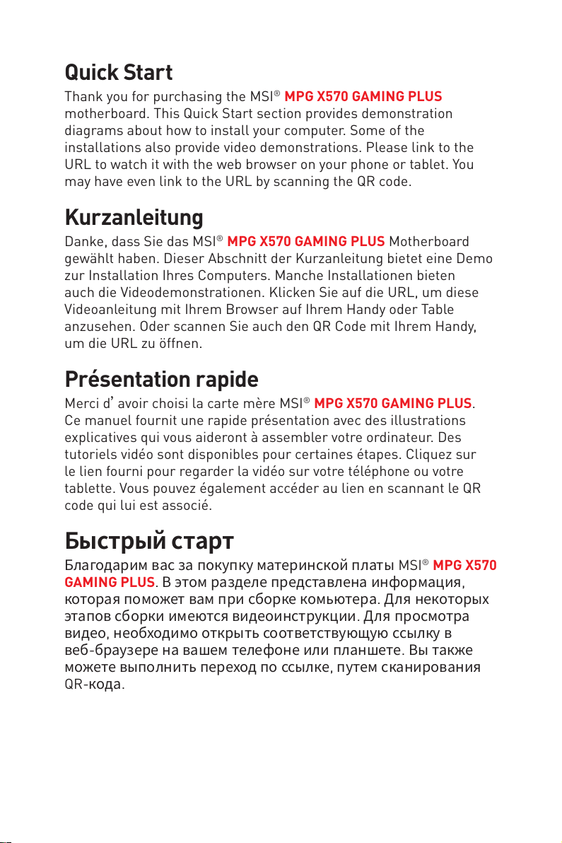
Installing a Processor/ Installation des Prozessors/ Installer un
processeur/ Установка процессора
Youtube
3
2
1
5
4
Quick Start
II
8
6
9
7
CPU_FAN1
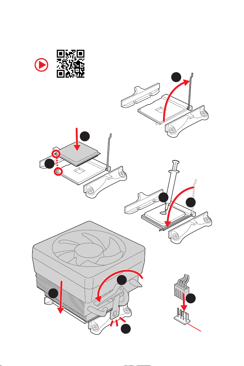
Important
If you are installing the screw-type CPU heatsink, please follow the figure below to
remove the retention module first and then install the heatsink.
Wenn Sie einen CPU-Kühler mit Schraubenbefestigung einsetzen, folgen Sie bitte
den Anweisungen unten um das Retention-Modul zu entfernen und den Kühler zu
installieren.
Si vous voulez installer un ventirad pour processeur à vis, veuillez suivre les
instructions ci-dessous pour d’abord retirer le module de rétention puis installer le
ventirad.
В случае установки процессорного кулера с системой крепления на винтах,
следуйте указаниям на рисунке ниже для снятия пластикового модуля
крепления. Затем установите кулер.
1
2
3
Quick Start
III
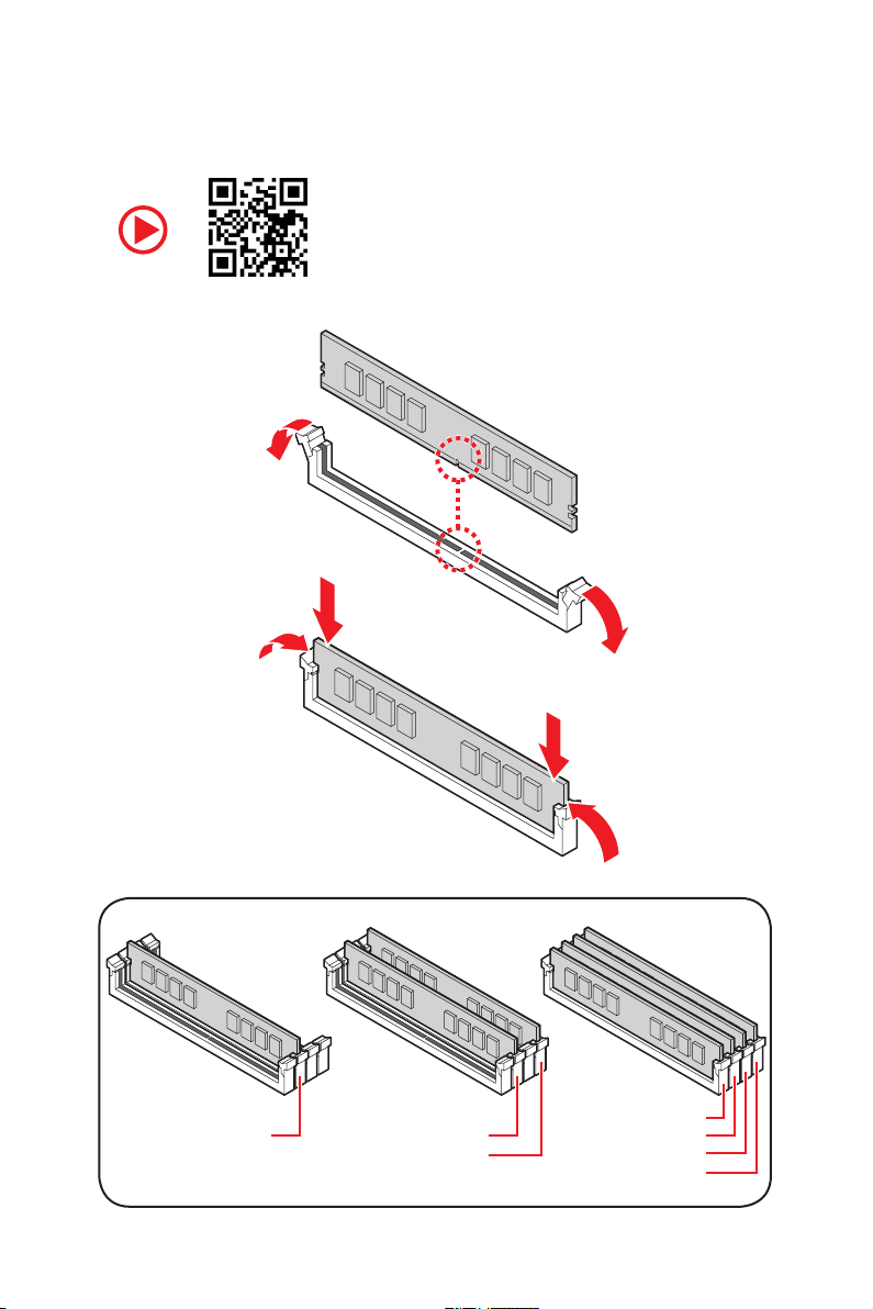
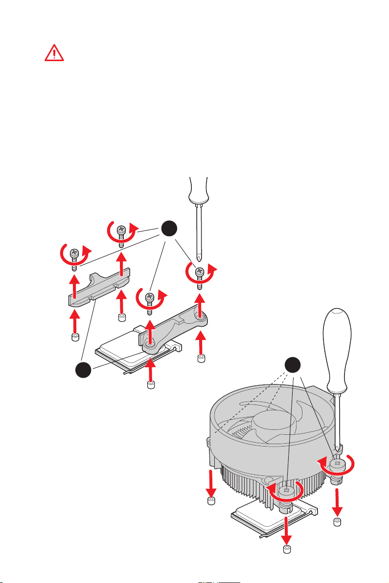
Installing DDR4 memory/ Installation des DDR4-Speichers/
Installer une mémoire DDR4/ Установка памяти DDR4
Youtube
IV
Quick Start
DIMMA2 DIMMA2
DIMMB2
DIMMA1
DIMMA2
DIMMB1
DIMMB2
RESET SW
POWER SW
POWER LED+
POWER LED-
HDD LED
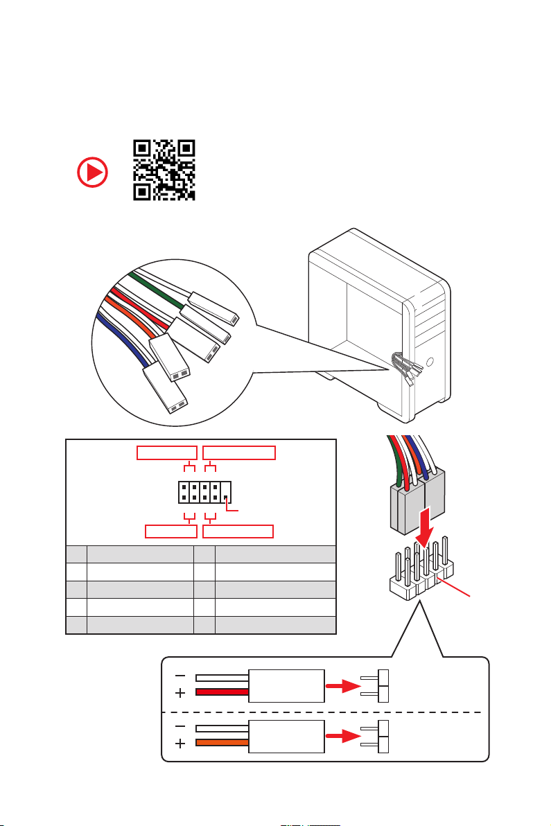
Connecting the Front Panel Header/ Anschließen der
Frontpanel-Stiftleiste/ Connecter un connecteur du panneau
avant/ Подключение разъемов передней панели
Youtube
Power LED
JFP1
Power Switch
+++—
——
2 10
1
—
+
9
Reserved
HDD LED Reset Switch
1 HDD LED + 2 Power LED +
3 HDD LED — 4 Power LED —
5 Reset Switch 6 Power Switch
7 Reset Switch 8 Power Switch
9 Reserved 10 No Pin
HDD LED
POWER LED
RESET SW
HDD LED
HDD LED HDD LED +
POWER LED POWER LED +
Quick Start
JFP1
V
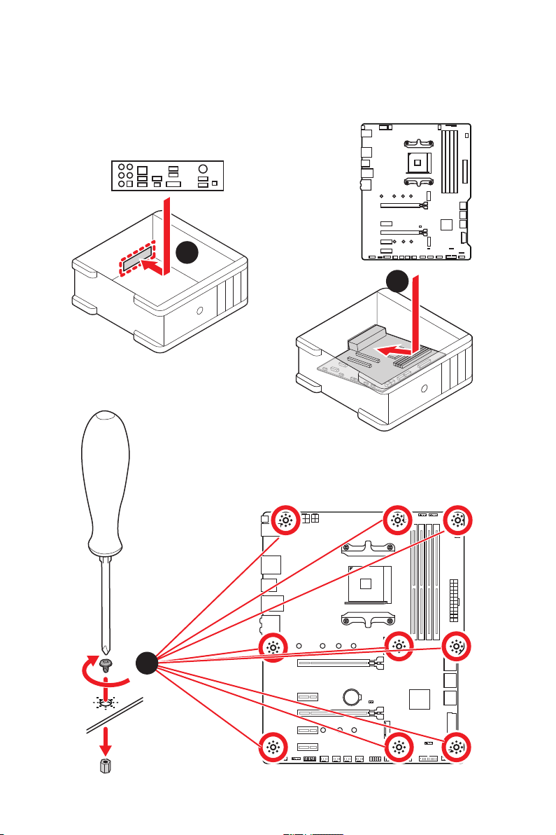
Installing the Motherboard/ Installation des Motherboards/
Installer la carte mère/ Установка материнской платы
1
2
VI
3
BAT1
Quick Start
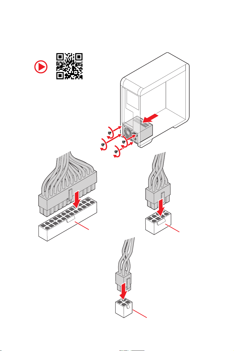
Connecting the Power Connectors/ Stromanschlüsse
anschliessen/ Connecter les câbles du module d’alimentation/
Подключение разъемов питания
Youtube
ATX_PWR1
CPU_PWR2
CPU_PWR1
Quick Start
VII
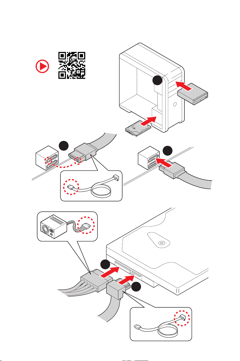
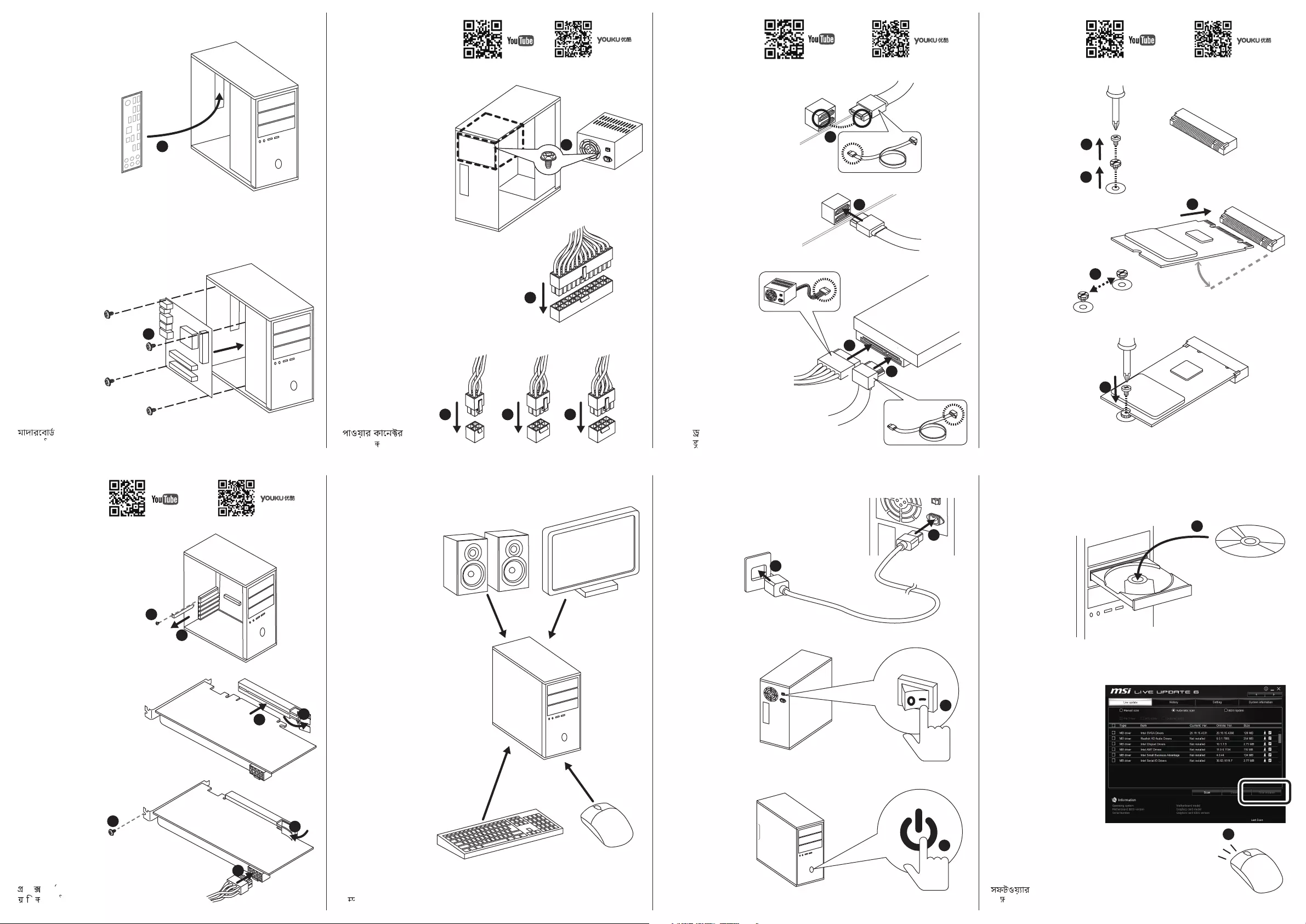
Installing SATA Drives/ Installation der SATA-Laufwerke/
Installer le disque dur SATA/ Установка дисков SATA
Youtube
2
1
3
VIII
5
4
Quick Start
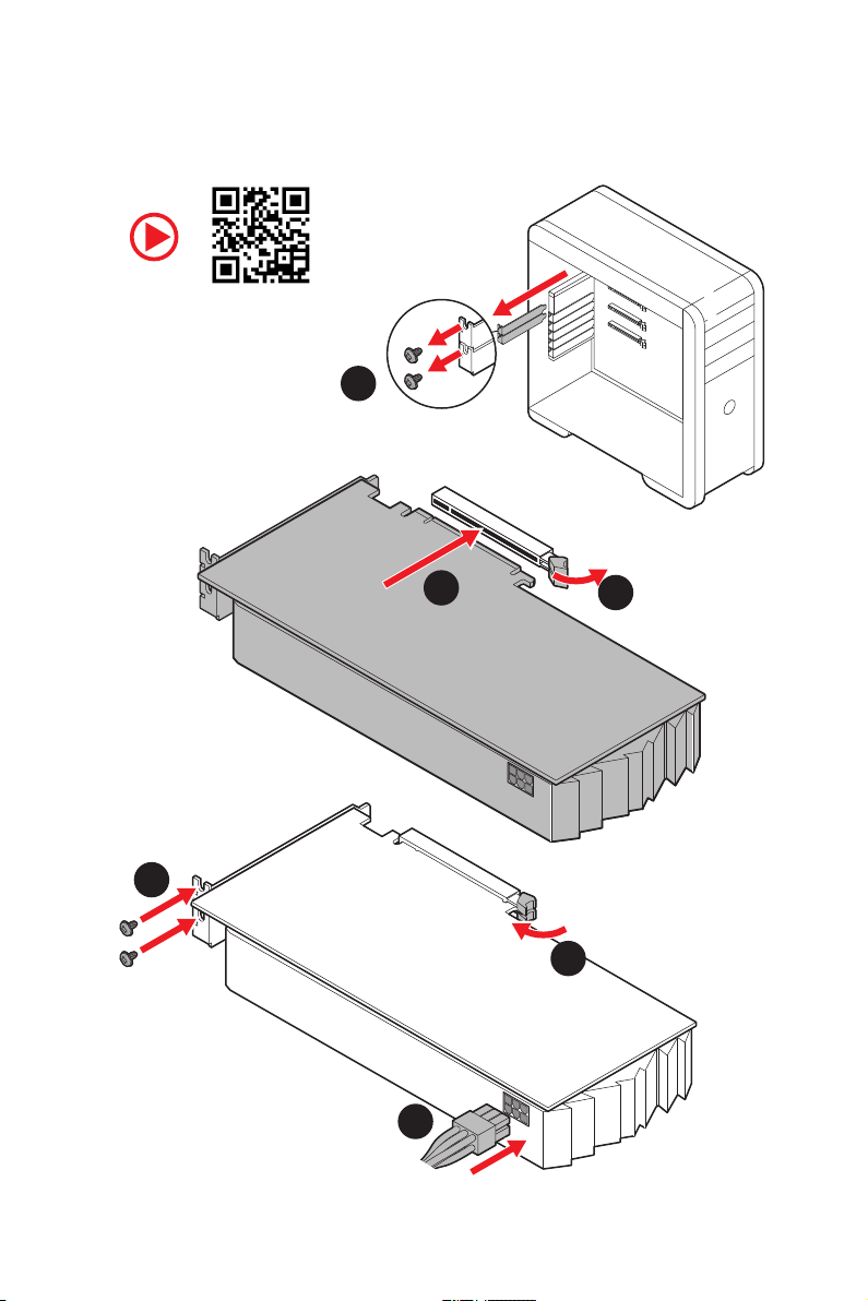
Installing a Graphics Card/ Einbau der Grafikkarte/ Installer
une carte graphique/ Установка дискретной видеокарты
Youtube
1
3
2
5
4
6
Quick Start
IX
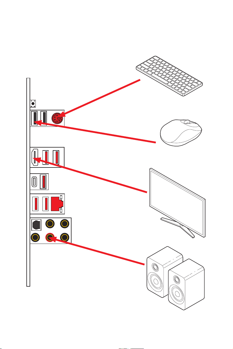
Connecting Peripheral Devices/ Peripheriegeräte/
Connecter un périphérique anschliessen/ Подключение
периферийных устройств
Processor with integrated graphics
Quick Start
X
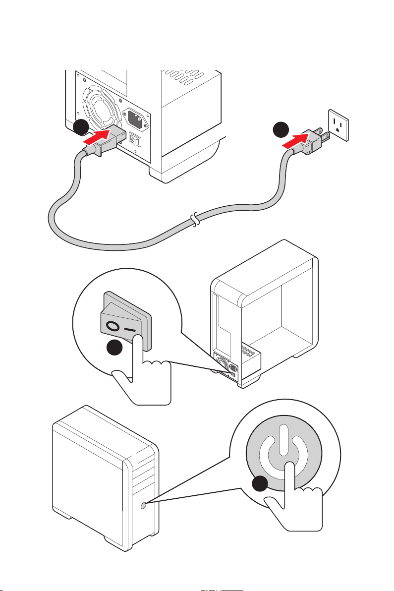
Power On/ Einschalten/ Mettre sous-tension/ Включение
питания
1
2
3
4
Quick Start
XI

NOTE
XII
Quick Start

Contents
Safety Information ……………………………………………………………………………………. 2
Specifications …………………………………………………………………………………………… 3
Package contents …………………………………………………………………………………….. 8
Rear I/O Panel …………………………………………………………………………………………. 9
LAN Port LED Status Table…………………………………………………………………………. 9
Audio Ports Configuration ………………………………………………………………………….. 9
Realtek Audio Console …………………………………………………………………………….. 10
Overview of Components ………………………………………………………………………… 12
Processor Socket …………………………………………………………………………………….. 13
DIMM Slots ……………………………………………………………………………………………… 14
PCI_E1~5: PCIe Expansion Slots ……………………………………………………………….. 15
M2_1~2: M.2 Slots (Key M) ……………………………………………………………………….. 16
SATA1~6: SATA 6Gb/s Connectors …………………………………………………………….. 18
JFP1, JFP2: Front Panel Connectors …………………………………………………………. 18
CPU_PWR1~2, ATX_PWR1: Power Connectors …………………………………………… 19
CPU_FAN1, PUMP_FAN1, SYS_FAN1~4: Fan Connectors …………………………….. 20
JUSB3~4: USB 3.2 Gen1 Connectors …………………………………………………………. 21
JUSB1~2: USB 2.0 Connectors ………………………………………………………………….. 21
JAUD1: Front Audio Connector ………………………………………………………………….22
JCOM1: Serial Port Connector ………………………………………………………………….. 22
JCI1: Chassis Intrusion Connector …………………………………………………………….. 23
JBAT1: Clear CMOS (Reset BIOS) Jumper ………………………………………………….. 24
EZ Debug LED …………………………………………………………………………………………. 24
JRGB1~2: RGB LED connectors ………………………………………………………………… 25
JRAINBOW1~2: Addressable RGB LED connectors ……………………………………… 26
Installing OS, Drivers & Utilities ………………………………………………………………. 27
Installing Windows® 10 …………………………………………………………………………….. 27
Installing Drivers …………………………………………………………………………………….. 27
Installing Utilities ……………………………………………………………………………………. 27
BIOS Setup …………………………………………………………………………………………….. 28
Entering BIOS Setup ………………………………………………………………………………… 28
Resetting BIOS ………………………………………………………………………………………… 29
Updating BIOS …………………………………………………………………………………………. 29
EZ Mode …………………………………………………………………………………………………. 31
Advanced Mode ………………………………………………………………………………………. 33
OC Menu…………………………………………………………………………………………………. 34
Contents
1

Safety Information
y The components included in this package are prone to damage from electrostatic
discharge (ESD). Please adhere to the following instructions to ensure successful
computer assembly.
y Ensure that all components are securely connected. Loose connections may cause
the computer to not recognize a component or fail to start.
y Hold the motherboard by the edges to avoid touching sensitive components.
y It is recommended to wear an electrostatic discharge (ESD) wrist strap when
handling the motherboard to prevent electrostatic damage. If an ESD wrist strap is
not available, discharge yourself of static electricity by touching another metal object
before handling the motherboard.
y Store the motherboard in an electrostatic shielding container or on an anti-static pad
whenever the motherboard is not installed.
y Before turning on the computer, ensure that there are no loose screws or metal
components on the motherboard or anywhere within the computer case.
y Do not boot the computer before installation is completed. This could cause
permanent damage to the components as well as injury to the user.
y If you need help during any installation step, please consult a certified computer
technician.
y Always turn off the power supply and unplug the power cord from the power outlet
before installing or removing any computer component.
y Keep this user guide for future reference.
y Keep this motherboard away from humidity.
y Make sure that your electrical outlet provides the same voltage as is indicated on the
PSU, before connecting the PSU to the electrical outlet.
y Place the power cord such a way that people can not step on it. Do not place anything
over the power cord.
y All cautions and warnings on the motherboard should be noted.
y If any of the following situations arises, get the motherboard checked by service
personnel:
Liquid has penetrated into the computer.
The motherboard has been exposed to moisture.
The motherboard does not work well or you can not get it work according to user
guide.
The motherboard has been dropped and damaged.
The motherboard has obvious sign of breakage.
y Do not leave this motherboard in an environment above 60°C (140°F), it may damage
the motherboard.
Safety Information
2
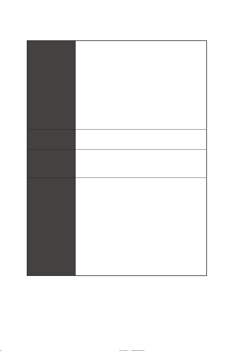
Specifications
CPU
Radeon™ Vega Graphics and 2nd Gen AMD Ryzen™ with
Radeon™ Graphics Desktop Processors for Socket AM4
Chipset AMD
y 4x DDR4 memory slots, support up to 128GB* (depending
on the processor)
Supports 2nd and 3rd Gen AMD Ryzen™, Ryzen™ with
Memory
y Dual channel memory architecture
y Supports non-ECC UDIMM memory
y Supports ECC UDIMM memory (non-ECC mode)
y Supports un-buffered memory
* Please refer www.msi.com for more information on compatible memory.
y 1x PCIe 4.0/ 3.0 x16 slot (PCI_E1)
Expansion Slot
y 1x PCIe 4.0/ 3.0 x16 slot (PCI_E3, supports x4 mode)
y 3x PCIe 3.0 x1 slots*
* PCI_E2 will be unavailable when installing the PCIe card in PCI_E4 slot.
** The speeds may vary for different devices
®
X570 Chipset
Supports DDR4 1866/ 2133/ 2400/ 2666 MHz by JEDEC,
and 2666/ 2800/ 2933/ 3000/ 3066/ 3200/ 3466/ 3600/
3733/ 3866/ 4000/ 4133/ 4266/ 4400 MHz by A-XMP OC
MODE
3rd Gen AMD Ryzen™ support PCIe 4.0 x16 mode
2nd Gen AMD Ryzen™ support PCIe 3.0 x16 mode
Ryzen™ with Radeon™ Vega Graphics and 2nd Gen
AMD Ryzen™ with Radeon™ Graphics support PCIe 3.0
x8 mode
y 1x HDMI 1.4 port, supports a maximum resolution of
4096×2160 @24Hz*
Onboard Graphics
* Only support when using Ryzen™ with Radeon™ Vega Graphics and 2nd Gen
AMD Ryzen™ with Radeon™ Graphics Processors
* Maximum shared memory of 2048 MB
Multi-GPU y Supports 2-Way AMD® CrossFire™ Technology
®
LAN y 1x Realtek
8111H Gigabit LAN Controller
Continued on next page
Specifications
3
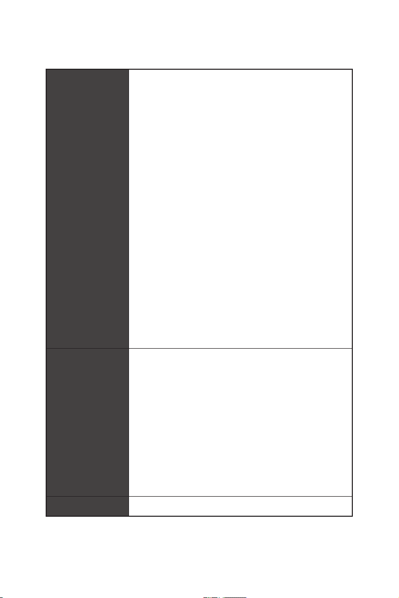
Storage
RAID
Audio
USB
Continued from previous page
y 6x SATA 6Gb/s ports
y 2x M.2 slots (Key M)*
®
M2_1 slot (from AMD
Processor)
Supports PCIe 4.0 x4 (3rd Gen AMD Ryzen™)
Supports PCIe 3.0 x4 (2nd Gen AMD Ryzen™, Ryzen™
with Radeon™ Vega Graphics and 2nd Gen AMD
Ryzen™ with Radeon™ Graphics)
Supports 2242/ 2260/ 2280/ 22110 storage devices
M2_2 slot (from AMD
®
X570 Chipset)
Supports PCIe 3.0 x4 and SATA 6Gb/s
Supports 2242/ 2260/ 2280 storage devices
®
AMD
X570 Chipset
y Supports RAID 0, RAID 1 and RAID 10
®
Realtek
ALC1220 Codec
y 7.1-Channel High Definition Audio
y Supports Optical S/PDIF output
®
y AMD
X570 Chipset
6x USB 3.2 Gen 1 (SuperSpeed USB) ports (2 Type-A
ports on the back panel, 4 ports available through the
internal USB 3.2 Gen 1 connectors)
6x USB 2.0 (High-speed USB) ports (2 Type-A ports on
the back panel, 4 ports available through the internal
USB 2.0 connectors)
®
y AMD
Processor
2x USB 3.2 Gen2 (3rd Gen AMD Ryzen™) or USB 3.2
Gen1 (2nd Gen AMD Ryzen™, Ryzen™ with Radeon™
Vega Graphics and 2nd Gen AMD Ryzen™ with Radeon™
Graphics) ports (1x Type-A & 1x Type-C) on the back
panel
2x USB 3.2 Gen1 (SuperSpeed USB) Type-A ports on the
back panel
Specifications
4
Continued on next page
Internal Connectors
Continued from previous page
y 1x 24-pin ATX main power connector
y 1x 8-pin ATX 12V power connector
y 1x 4-pin ATX 12V power connector
y 6x SATA 6Gb/s connectors
y 2x USB 2.0 connectors (supports additional 4 USB 2.0
ports)
y 2x USB 3.2 Gen1 connectors (supports additional 4 USB 3.2
Gen1 ports)
y 1x 4-pin CPU fan connector
y 1x 4-pin water-pump connector
y 4x 4-pin system fan connectors
y 1x Front panel audio connector
y 2x System panel connectors
y 1x TPM module connector
y 1x Serial port connector
y 1x Clear CMOS jumper
y 1x Chassis Intrusion connector
y 2x 4-pin RGB LED connectors
y 2x 3-pin RAINBOW LED connectors
y 4x EZ Debug LEDs
y 1x Flash BIOS Button
y 1x PS/2 keyboard/ mouse combo port
y 2x USB 2.0 ports
y 4x USB 3.2 Gen 1 ports
Back Panel
Connectors
I/O Controller NUVOTON NCT6797 Controller Chip
y 1x HDMI port
y 1x USB 3.2 Gen 2/ 1 Type A port
y 1x USB 3.2 Gen 2/1 Type C port
y 1x LAN(RJ45) port
y 5x OFC audio jacks
y 1x Optical S/PDIF Out connector
Continued on next page
Specifications
5
Hardware Monitor
Continued from previous page
y CPU/ System/ Chipset temperature detection
y CPU/ System/ Chipset fan speed detection
y CPU/ System/ Chipset fan speed control
Form Factor
BIOS Features
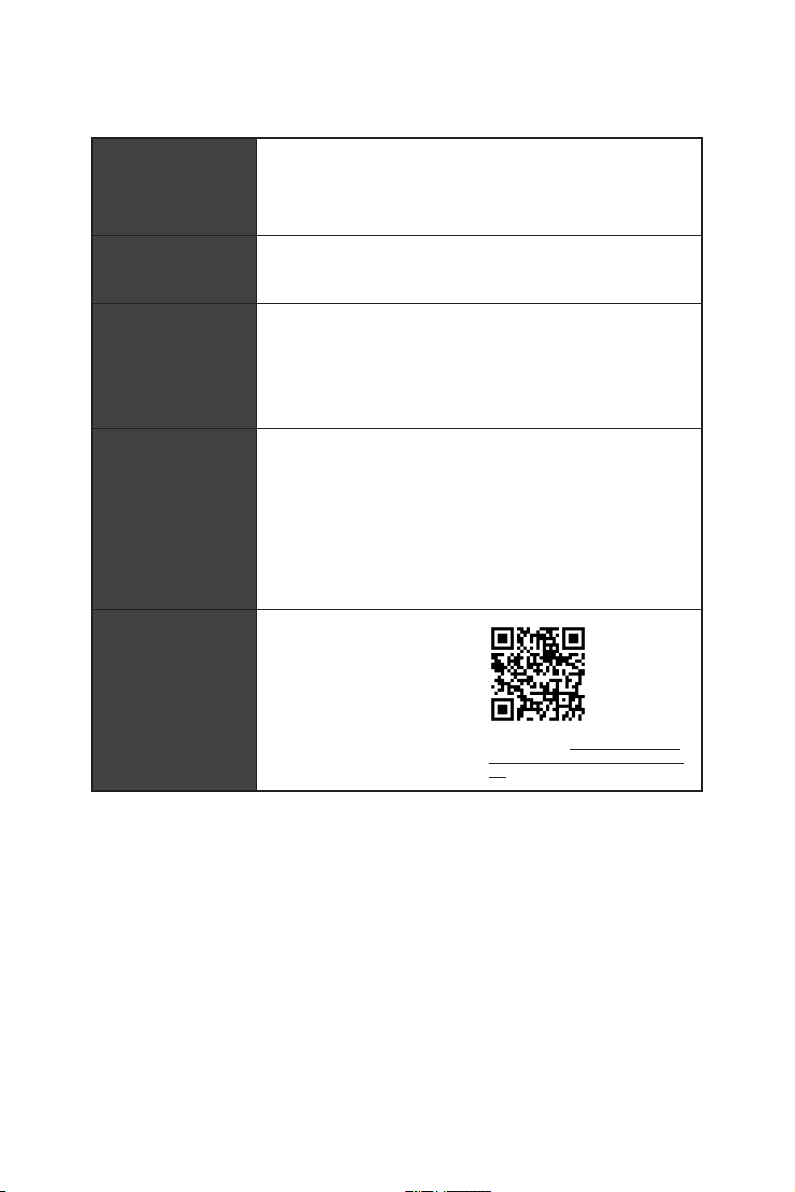
Software
Dragon Center
Features
y ATX Form Factor
y 12 in. x 9.6 in. (30.4 cm x 24.3 cm)
y 1x 256 Mb flash
y UEFI AMI BIOS
y ACPI 6.1, SM BIOS 2.8
y Multi-language
y Drivers
y DRAGON CENTER
y CPU-Z MSI GAMING
y MSI App Player (BlueStacks)
y Google Chrome™ ,Google Toolbar, Google Drive
y Norton™ Internet Security Solution
y DRAGON OPTIMIZATION
y OC Performance
y Hardware Monitor
y True Color
y Mystic Light
y Live Update
Please refer to http://download.msi.
com/manual/mb/DRAGONCENTER2.
pdf for more details.
Continued on next page
Specifications
6

Special Features
Continued from previous page
y Audio
Audio Boost 4
y Storage
Lightning Gen 4 M.2
Turbo M.2
y Fan
Pump Fan
GAMING Fan Control
y LED
Mystic Light 3
Mystic Light Extension (RGB)
Mystic Light Extension (RAINBOW)
Mystic Light Sync
EZ DEBUG LED
y Protection
PCIe Steel Armor
y Performance
Multi GPU-CrossFire Technology
DDR4 Boost
Core Boost
GAME Boost
USB with type A+C
AMD Turbo USB 3.2 Gen 2
y BIOS
Click BIOS 5
Flash BIOS
y Certification
GAMING Certified
Specifications
7
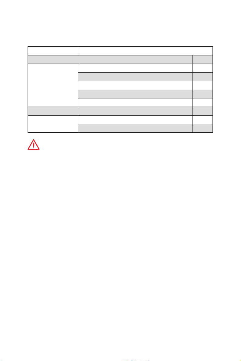
Package contents
Please check the contents of your motherboard package. It should contain:
Motherboard MPG X570 GAMING PLUS
Cable SATA 6Gb/s Cables 2
M.2 Heatsink 1
8.5H M.2 screws 2
Accessories
Application DVD Driver DVD 1
Documentation
Important
If any of the above items are damaged or missing, please contact your retailer.
Case Badge 1
SATA Cable Labels 1
Product Registration Card 1
User Manual 1
Quick Installation Guide 1
Package contents
8
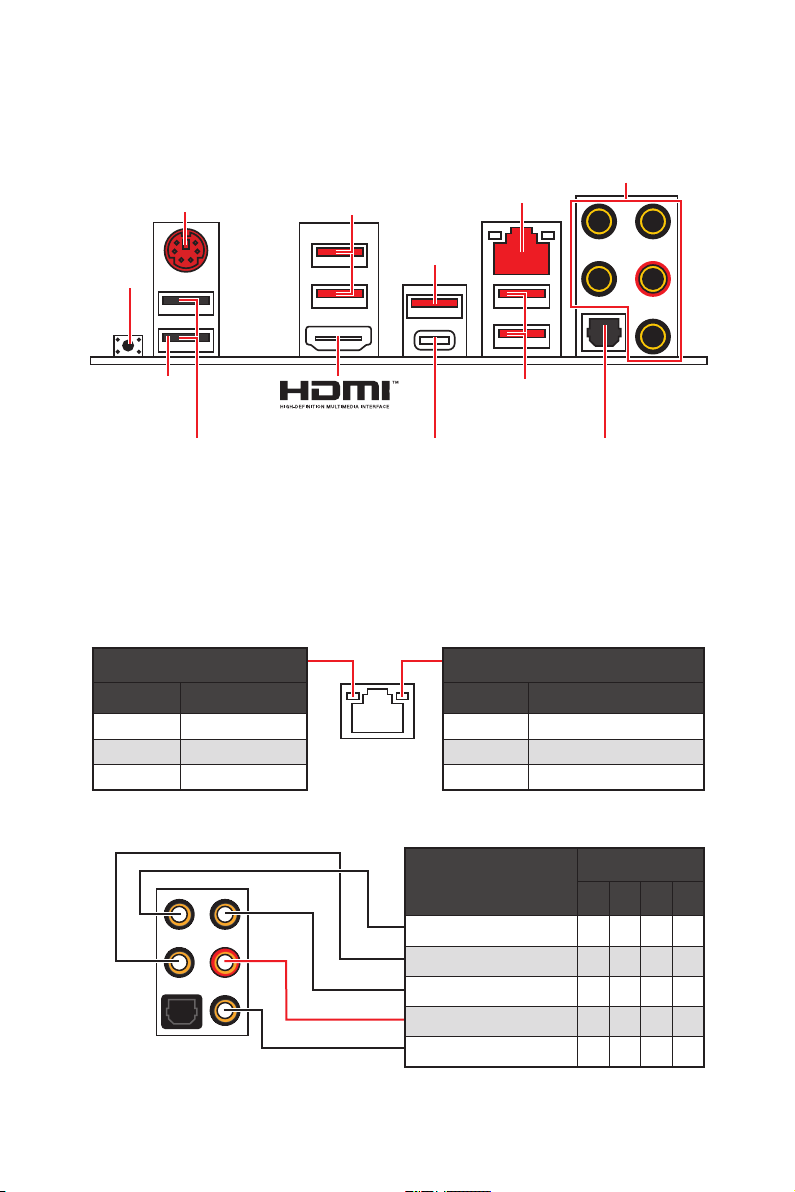
Rear I/O Panel
PS/2
USB 3.2
Gen1
Type-A
LAN
Audio Ports
USB 3.2
Gen 2
Type-A*
Flash BIOS
Button
Flash BIOS
Port
USB 3.2
Gen 1
Type-A
USB 2.0 Type-A
USB 3.2 Gen 2
Optical S/PDIF-Out
Type-C*
*USB 3.2 Gen2 (3rd Gen AMD Ryzen™) or USB 3.2 Gen1 (2nd Gen AMD Ryzen™/Ryzen™
with Radeon™ Vega Graphics and 2nd Gen AMD Ryzen™ with Radeon™Graphics)
y Flash BIOS Port/ Button — Please refer to page 30 for Updating BIOS with Flash BIOS
Button.
LAN Port LED Status Table
Link/ Activity LED
Status Description
Off No link
Yellow Linked
Blinking Data activity
Speed LED
Status Description
Off 10 Mbps connection
Green 100 Mbps connection
Orange 1 Gbps connection
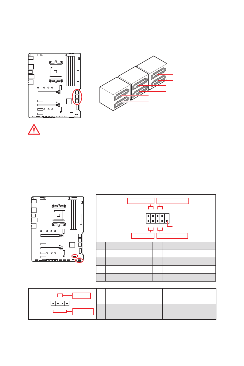
Audio Ports Configuration
Audio Ports
Channel
2 4 6 8
Center/ Subwoofer Out ● ●
Rear Speaker Out ● ● ●
Line-In/ Side Speaker Out ●
Line-Out/ Front Speaker Out ● ● ● ●
Mic In
(●: connected, Blank: empty)
Rear I/O Panel
9
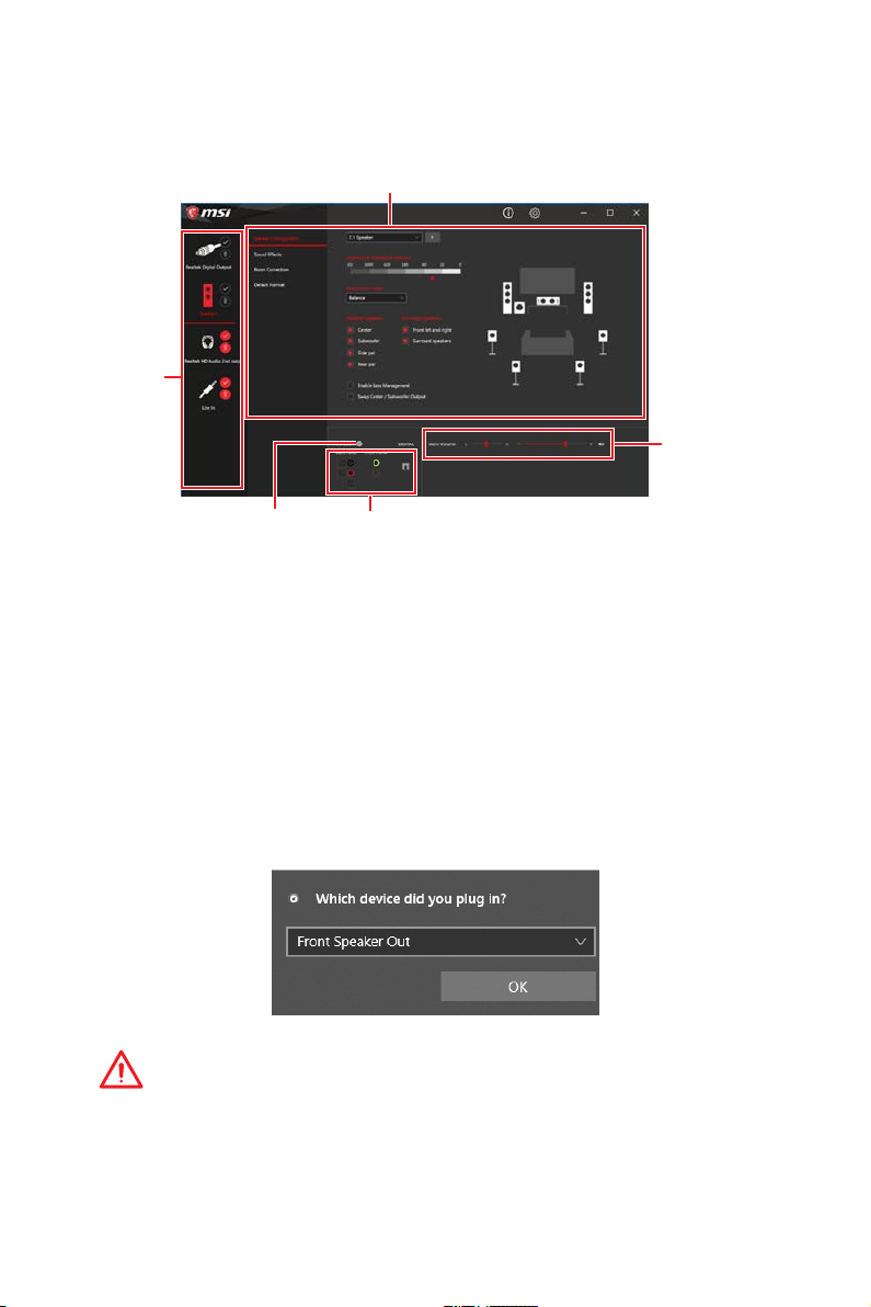
Realtek Audio Console
After Realtek Audio Console is installed. You can use it to change sound settings to get
better sound experience.
Device
Selection
Application Enhancement
Main Volume
Connector Settings
Jack Status
y Device Selection — allows you to select a audio output source to change the related
options. The check sign indicates the devices as default.
y Application Enhancement — the array of options will provide you a complete guidance
of anticipated sound effect for both output and input device.
y Main Volume — controls the volume or balance the right/left side of the speakers that
you plugged in front or rear panel by adjust the bar.
y Jack Status — depicts all render and capture devices currently connected with your
computer.
y Connector Settings — configures the connection settings.
Auto popup dialog
When you plug into a device at an audio jack, a dialogue window will pop up asking you
which device is current connected.
Each jack corresponds to its default setting as shown on the next page.
Important
The pictures above for reference only and may vary from the product you purchased.
Rear I/O Panel
10
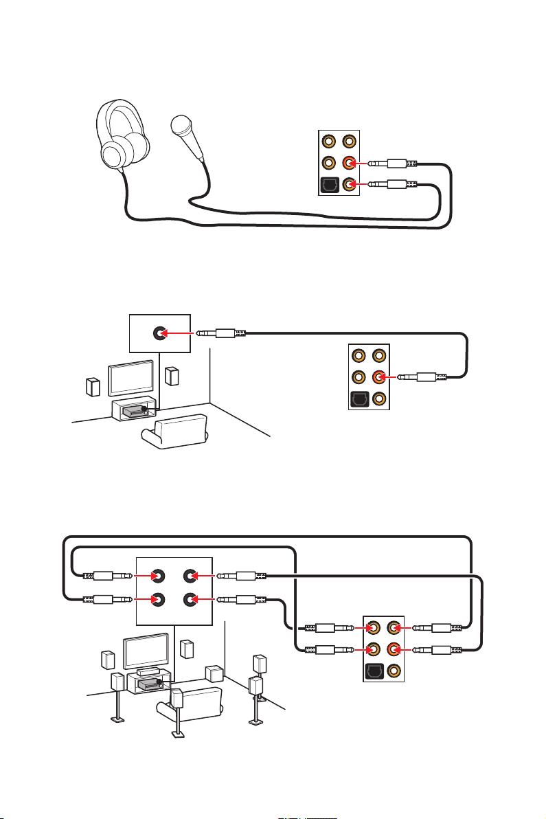
Audio jacks to headphone and microphone diagram
Audio jacks to stereo speakers diagram
AUDIO INPUT
Audio jacks to 7.1-channel speakers diagram
AUDIO INPUT
Rear Front
Side Center/
Subwoofer
Rear I/O Panel
11
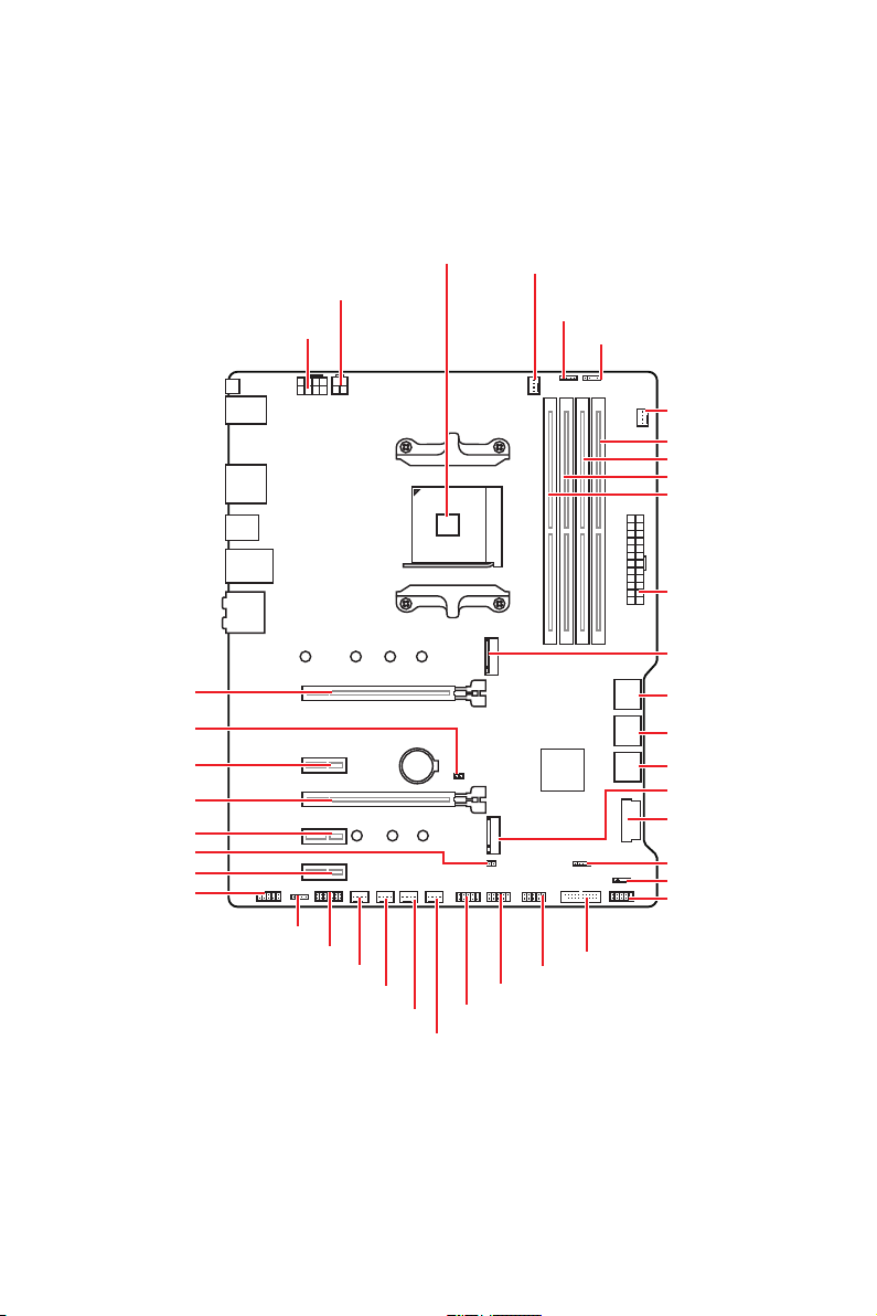
Overview of Components
Processor
Socket
CPU_PWR2
CPU_PWR1
CPU_FAN1
JRGB2
JRAINBOW2
PUMP_FAN1
DIMMB2
DIMMB1
DIMMA2
DIMMA1
ATX_PWR1
M2_1
PCI_E1
JBAT1
PCI_E2
PCI_E3
PCI_E4
JCI1
PCI_E5
JAUD1
Overview of Components
12
JRGB1
JTPM1
SYS_FAN1
SYS_FAN2
SYS_FAN3
BAT1
JCOM1
SYS_FAN4
JUSB1
JUSB2
JUSB3
SATA▼5▲6
SATA▼3▲4
SATA▼1▲2
M2_2
JUSB4
JFP2
JRAINBOW1
JFP1
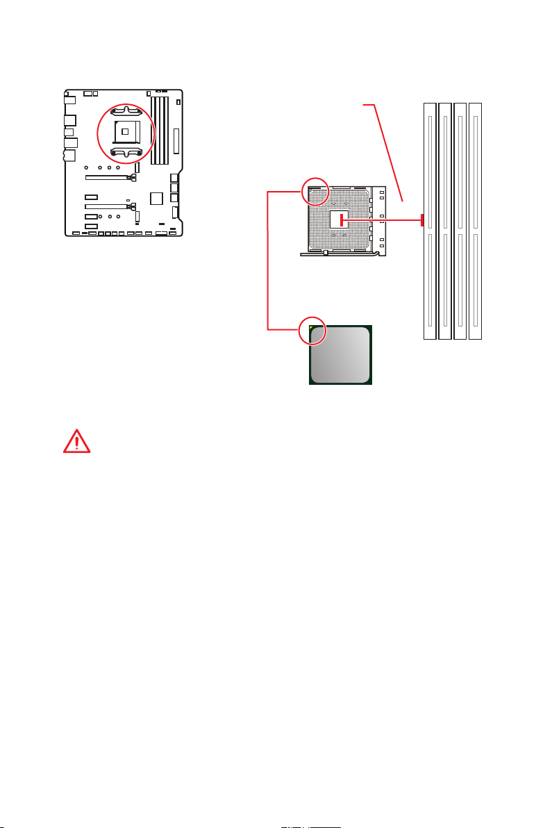
Processor Socket
Distance from the center of the
CPU to the nearest DIMM slot.
52.5 mm
Introduction to the AM4 CPU
The surface of the AM4 CPU has a
yellow triangle to assist in correctly
lining up the CPU for motherboard
placement. The yellow triangle is
the Pin 1 indicator.
Important
y
When changing the processor, the system configuration could be cleared and reset
BIOS to default values, due to the AM4 processor’s architecture.
y
Always unplug the power cord from the power outlet before installing or removing
the CPU.
y
When installing a CPU, always remember to install a CPU heatsink. A CPU heatsink
is necessary to prevent overheating and maintain system stability.
y
Confirm that the CPU heatsink has formed a tight seal with the CPU before booting
your system.
y
Overheating can seriously damage the CPU and motherboard. Always make sure
the cooling fans work properly to protect the CPU from overheating. Be sure to apply
an even layer of thermal paste (or thermal tape) between the CPU and the heatsink to
enhance heat dissipation.
y
If you purchased a separate CPU and heatsink/ cooler, Please refer to the
documentation in the heatsink/ cooler package for more details about installation.
y
This motherboard is designed to support overclocking. Before attempting to
overclock, please make sure that all other system components can tolerate
overclocking. Any attempt to operate beyond product specifications is not
recommended. MSI
operation beyond product specifications.
®
does not guarantee the damages or risks caused by inadequate
Overview of Components
13
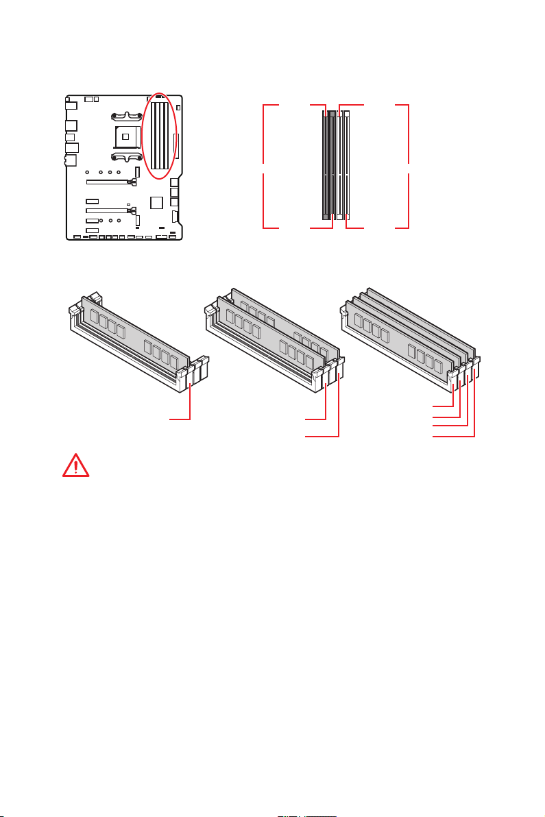
DIMM Slots
DIMMA1 DIMMB1
Channel A Channel B
DIMMA2 DIMMB2
Memory module installation recommendation
DIMMA1
DIMMA2
DIMMA2
DIMMB2 DIMMB2
Important
y
Always insert memory modules in the DIMMA2 slot first.
y
Due to chipset resource usage, the available capacity of memory will be a little less
than the amount of installed.
y
Based on CPU specification, the Memory DIMM voltage below 1.35V is suggested to
protect the CPU.
y
Please note that the maximum capacity of addressable memory is 4GB or less
for 32-bit Windows OS due to the memory address limitation. Therefore, we
recommended that you to install 64-bit Windows OS if you want to install more than
4GB memory on the motherboard.
y
Some memory may operate at a lower frequency than the marked value when
overclocking due to the memory frequency operates dependent on its Serial Presence
Detect (SPD). Go to BIOS and find the DRAM Frequency to set the memory frequency if
you want to operate the memory at the marked or at a higher frequency.
y
It is recommended to use a more efficient memory cooling system for full DIMMs
installation or overclocking.
y
The stability and compatibility of installed memory module depend on installed CPU
and devices when overclocking.
DIMMA2
DIMMB1
Overview of Components
14
PCI_E1~5: PCIe Expansion Slots
Ryzen™ with Radeon™
Slots 3rd Gen AMD Ryzen™ 2nd Gen AMD Ryzen™
PCI_E1 PCIe 4.0 x16 PCIe 3.0 x16 PCIe 3.0 x8
PCI_E2 PCIe 3.0 x1 PCIe 3.0 x1 PCIe 3.0 x1
PCI_E3 PCIe 4.0 x4 PCIe 3.0 x4 PCIe 3.0 x4
PCI_E4 PCIe 3.0 x1 PCIe 3.0 x1 PCIe 3.0 x1
PCI_E5 PCIe 3.0 x1 PCIe 3.0 x1 PCIe 3.0 x1
Important
y
If you install a large and heavy graphics card, you need to use a tool such as MSI
Gaming Series Graphics Card Bolster to support its weight to prevent deformation of
the slot.
y
For a single PCIe x16 expansion card installation with optimum performance, using
the PCI_E1 slot is recommended.
y
When adding or removing expansion cards, always turn off the power supply and
unplug the power supply power cable from the power outlet. Read the expansion
card’s documentation to check for any necessary additional hardware or software
changes.
PCIe bandwidth table
Slot Single 2-Way
@4.0 x16*
PCI_E1 (CPU)
PCI_E2 (PCH) 3.0 x1 ― 3.0 x1 ―
PCI_E3 (PCH)
PCI_E4 (PCH) ― 3.0 x1 ― 3.0 x1
PCI_E5 (PCH) 3.0 x1 3.0 x1
(─: unavailable, @: graphics card, *: for 3rd Gen AMD Ryzen™, **: for 2nd Gen AMD
Ryzen™, ***: for Ryzen™ with Radeon™ Vega Graphics and 2nd Gen AMD Ryzen™ with
Radeon™ Graphics)
or @3.0 x16**
or @3.0 x8***
4.0 x4*
or 3.0 x4**
/
***
Vega Graphics and 2nd
Gen AMD Ryzen™ with
Radeon™ Graphics
@4.0 x16*
or @3.0 x16**
or @3.0 x8***
@4.0 x4*
or @3.0 x4**/***
Overview of Components
15
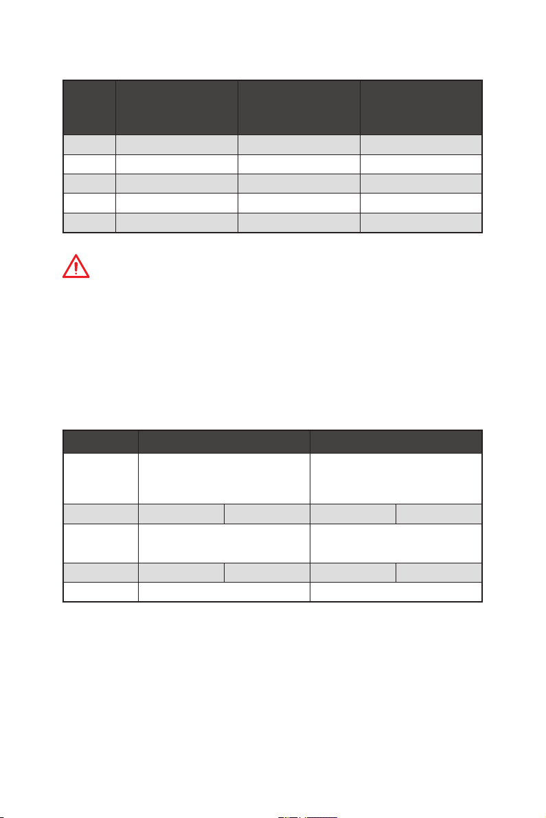
M2_1~2: M.2 Slots (Key M)
The following table describes the relationship between the
M.2 slots and the PCIe bandwidth of the processors.
Ryzen™ with
Radeon™ Vega
Graphics and 2nd Gen
AMD Ryzen™ with
Radeon™ Graphics
M2_1
M2_2
3rd Gen AMD
Slots
Ryzen™
M2_1 PCIe 4.0 x4 PCIe 3.0 x4 PCIe 3.0 x4
M2_2 PCIe 3.0 x4 PCIe 3.0 x4 PCIe 3.0 x4
2nd Gen AMD
Ryzen™
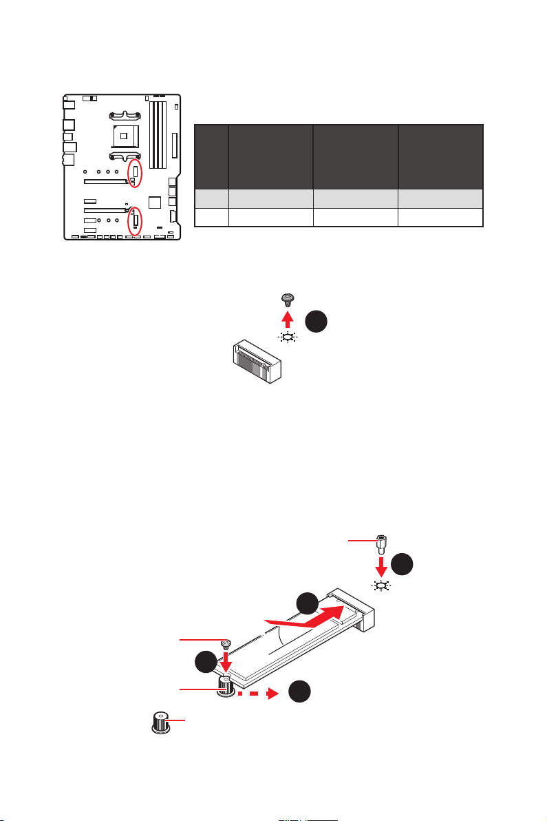
M2_1 installaion (including heatsink)
1. Loosen and remove the screw from the motherboard mounting stand.
1
2. Choose a heatsink standoff (6#23 or M3) provided with motherbaord package by
your need and secure it to the motherboard mounting stand.
3. For 2242/ 2260 M.2 SSD, please move and fasten the M.2 standoff to the
appropriate position to your M.2 SSD.
For 2280 M.2 SSD, please skip this step.
For 22110 M.2 SSD, please remove the M.2 standoff.
4. Insert your M.2 SSD into the M.2 slot at a 30-degree angle.
5. Secure the M.2 SSD in place with the 8.5H M.2 screw provided with motherboard
package. This step is for 2242/ 2260/ 2280 M.2 SSD only.
8.5H M.2 screw
Overview of Components
16
M.2 standoff
6#23 or M3 heatsink standoff
2
4
30º30º
5
3
heatsink standoff
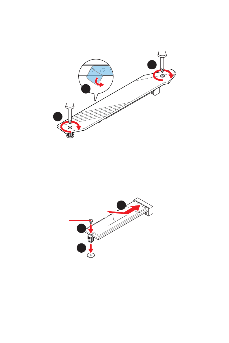
6. Remove the protective films from the thermal pads of M.2 heatsink.
7. Align the heatsink standoffs with the M.2 heatsink screws and then secure the M.2
heatsink.
7
6
7
M2_2 installation
1. Move and fasten the M.2 standoff to the appropriate position for your M.2 SSD.
2. Insert your M.2 SSD into the M.2 slot at a 30-degree angle.
3. Secure the M.2 SSD in place with the 8.5H M.2 screw provided with motherboard
package.
8.5H M.2 screw
M.2 standoff
2
30º30º
3
1
Overview of Components
17
SATA1~6: SATA 6Gb/s Connectors
These connectors are SATA 6Gb/s interface ports. Each connector can connect to one
SATA device.
SATA6
SATA5
SATA4
SATA3
SATA2
SATA1
Important
y
Please do not fold the SATA cable at a 90-degree angle. Data loss may result during
transmission otherwise.
y
SATA cables have identical plugs on either sides of the cable. However, it is
recommended that the flat connector be connected to the motherboard for space
saving purposes.
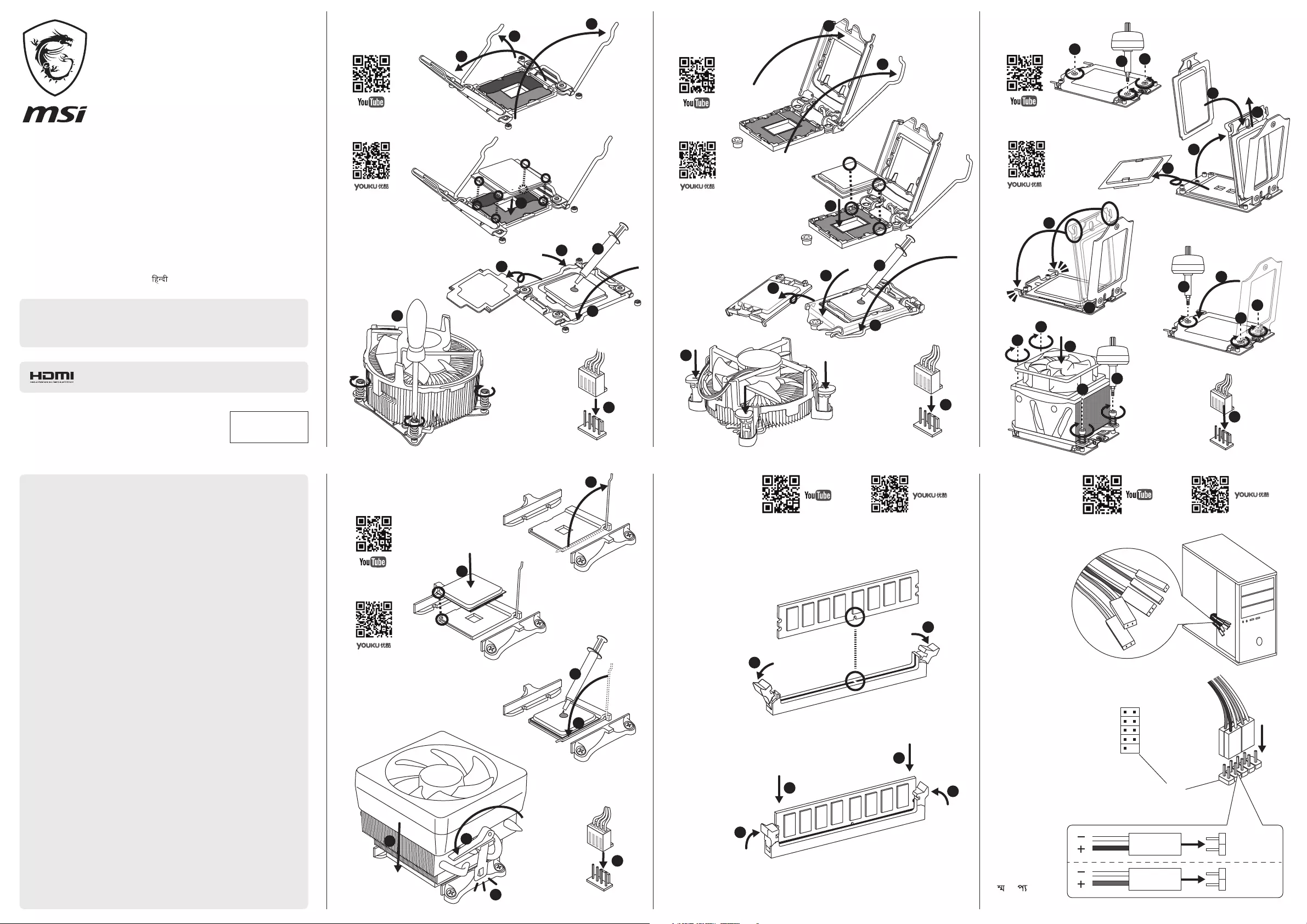
JFP1, JFP2: Front Panel Connectors
These connectors connect to the switches and LEDs on the front panel.
1
JFP2
Overview of Components
18
Power LED
JFP1
Power Switch
+++—
——
2 10
1
—
+
9
Reserved
HDD LED Reset Switch
1 HDD LED + 2 Power LED +
3 HDD LED — 4 Power LED —
5 Reset Switch 6 Power Switch
7 Reset Switch 8 Power Switch
9 Reserved 10 No Pin
Buzzer
++-
Speaker
1 Speaker — 2 Buzzer +
3 Buzzer — 4 Speaker +
Loading…
Table of Contents
- MSI MPG X570 GAMING PLUS Motherboard
- Preparing Tools and Components
- Safety Information
- Realtek Audio Console
- Installing OS, Drivers & Utilities
- Features
- Frequently Asked Questions
- Read User Manual Online (PDF format)
- Download This Manual (PDF format)

MSI MPG X570 GAMING PLUS Motherboard

Thank you for purchasing the MSI® MPG X570 GAMING PLUS motherboard. This Quick
Start section provides demonstration diagrams about how to install your
computer. Some of the installations also provide video demonstrations. Please
link to the URL to watch it with the web browser on your phone or tablet. You
may have even link to the URL by scanning the QR code.
Preparing Tools and Components

Safety Information
- The components included in this package are prone to damage from electrostatic discharge (ESD). Please adhere to the following instructions to ensure successful computer assembly.
- Ensure that all components are securely connected. Loose connections may cause the computer to not recognize a component or fail to start.
- Hold the motherboard by the edges to avoid touching sensitive components.
- It is recommended to wear an electrostatic discharge (ESD) wrist strap when handling the motherboard to prevent electrostatic damage. If an ESD wrist strap is not available, discharge yourself of static electricity by touching another metal object before handling the motherboard.
- Store the motherboard in an electrostatic shielding container or on an anti-static pad whenever the motherboard is not installed.
- Before turning on the computer, ensure that there are no loose screws or metal components on the motherboard or anywhere within the computer case.
- Do not boot the computer before installation is completed. This could cause permanent damage to the components as well as injury to the user.
- If you need help during any installation step, please consult a certified computer technician.
- Always turn off the power supply and unplug the power cord from the power outlet before installing or removing any computer component.
- Keep this user guide for future reference.
- Keep this motherboard away from humidity.
- Make sure that your electrical outlet provides the same voltage as is indicated on the PSU, before connecting the PSU to the electrical outlet.
- Place the power cord in such a way that people can not step on it. Do not place anything over the power cord.
- All cautions and warnings on the motherboard should be noted.
- If any of the following situations arises, get the motherboard checked by service personnel:
- Liquid has penetrated into the computer.
- The motherboard has been exposed to moisture.
- The motherboard does not work well or you can not get it to work according to the user guide.
- The motherboard has been dropped and damaged.
- The motherboard has obvious signs of breakage.
- Do not leave this motherboard in an environment above 60°C (140°F), it may damage the motherboard.
Realtek Audio Console
After Realtek Audio Console is installed. You can use it to change sound
settings to get a better sound experience.
- Device Selection – allows you to select an audio output source to change the related options. The check sign indicates the devices as default.
- Application Enhancement – the array of options will provide you with complete guidance on anticipated sound effects for both output and input devices.
- Main Volume – controls the volume or balance the right/left side of the speakers that you plugged into front or rear panel by adjust the bar.
- Jack Status – depicts all render and capture devices currently connected with your computer.
- Connector Settings – configures the connection settings.
Auto popup dialog
When you plug into a device at an audio jack, a dialogue window will pop up
asking you which device is currently connected.
- Each jack corresponds to its default setting as shown on the next page.
Important
The pictures above are for reference only and may vary from the product you
purchased.
Important
- Always insert memory modules in the DIMMA2 slot first.
- Due to chipset resource usage, the available capacity of memory will be a little less than the amount installed.
- Based on CPU specification, the Memory DIMM voltage below 1.35V is suggested to protect the CPU.
- Please note that the maximum capacity of addressable memory is 4GB or less for 32-bit Windows OS due to the memory address limitation. Therefore, we recommended that you install 64-bit Windows OS if you want to install more than 4GB memory on the motherboard.
- Some memory may operate at a lower frequency than the marked value when overclocking due to the memory frequency operating dependent on its Serial Presence Detect (SPD). Go to BIOS and find the DRAM Frequency to set the memory frequency if you want to operate the memory at the market or at a higher frequency.
- It is recommended to use a more efficient memory cooling system for full DIMMs installation or overclocking.
- The stability and compatibility of the installed memory modules depend on the installed CPU and devices when overclocking.
Installing OS, Drivers & Utilities
Please download and update the latest utilities and drivers at www.msi.com
Installing Windows® 10
- Power on the computer.
- Insert the Windows® 10 installation disc/USB into your computer.
- Press the Restart button on the computer case.
- Press the F11 key during the computer POST (Power-On Self Test) to get into Boot Menu.
- Select the Windows® 10 installation disc/USB from the Boot Menu.
- Press any key when the screen shows Press any key to boot from CD or DVD… message.
- Follow the instructions on the screen to install Windows® 10.
Installing Drivers
- Start up your computer in Windows® 10.
- Insert MSI® Driver Disc into your optical drive.
- Click the Select to choose what happens with this disc pop-up notification, then select Run DVDSetup.exe to open the installer. If you turn off the AutoPlay feature from the Windows Control Panel, you can still manually execute the DVDSetup.exe from the root path of the MSI Driver Disc.
- The installer will find and list all necessary drivers in the Drivers/Software tab.
- Click the Install button in the lower-right corner of the window.
- The drivers’ installation will then be in progress, after it has finished it will prompt you to restart.
- Click the OK button to finish.
- Restart your computer.
Installing Utilities
Before you install utilities, you must complete the driver’s installation.
- Open the installer as described above.
- Click the Utility tab.
- Select the utilities you want to install.
- Click the Install button in the lower-right corner of the window.
- The utility installation will then be in progress, after it has finished it will prompt you to restart.
- Click the OK button to finish.
- Restart your computer.
Features
GEN 4 SOLUTION FOR LIGHTNING
With MSI Lightning Gen 4 PCI-E, strike quickly. Enjoy unidirectional
transfer bandwidth of up to 64GB/s by connecting lightning-fast PCI-E 4.0
devices.
DESIGN BY FROZR HEATSINK
Controlling heat is crucial for motherboards with high performance. With
its PCI-E Gen4 capabilities, the X570 chipset is actively cooled to support
enormous data bandwidth.
SHIELD FROZR M.2 Maximize SSD performance and avoid sluggishness
Even the fastest SSDs in the world may slow down if they get too heated.
For M.2 SSDs to avoid thermal throttling and maintain peak performance, M.2
SHIELD FROZR extends the motherboard’s heatsink over the M.2 SSDs.
ADD AUDIO BOOST 4 TO YOUR GAME TO IMPROVE IT
Similar to a dedicated sound card, Audio Boost 4 with Nahimic provides an
HD audio processor, a separate amplifier, and premium audio capacitors that
are all physically separated from the rest of the motherboard circuitry to
guarantee the cleanest audio signal for precisely locating foes.
CREEPER BOOST
The most recent improvement to MSI’s motherboard CPU power delivery
mechanism is Core Boost. An enhanced circuit design results in a highly
efficient power system with exact current output to the CPU thanks to a
dedicated zone of premium power delivery components.
YOUR GAME-INSIDE BENEFIT
Utilize a variety of exclusive MSI GAMING tools to outwit and exceed your
opponents in-game. Software and hardware innovations that keep you one step
ahead of the competition and improve your abilities.
Frequently Asked Questions
What precautions should I take when handling the motherboard to prevent
electrostatic damage?
It is recommended to wear an electrostatic discharge (ESD) wrist strap when
handling the motherboard to prevent electrostatic damage. If an ESD wrist
strap is not available, discharge yourself of static electricity by touching
another metal object before handling the motherboard.
What should I do if any of the components are not recognized by the computer
or fail to start?
Ensure that all components are securely connected. Loose connections may cause
the computer to not recognize a component or fail to start.
Can I leave the motherboard in an environment above 60°C (140°F)?
No, it may damage the motherboard.
What is Realtek Audio Console and how can it improve my sound experience?
Realtek Audio Console is software that allows you to change sound settings to
get a better sound experience. You can select an audio output source to change
the related options, control the volume or balance the right/left side of the
speakers, and configure the connection settings.
What should I do if a dialogue window pops up asking me which device is
currently connected when I plug into an audio jack?
Each jack corresponds to its default setting as shown in the manual. Select
the appropriate device from the dialogue window.
What is Core Boost and how does it improve CPU power delivery?
Core Boost is an enhanced circuit design that results in a highly efficient
power system with exact current output to the CPU thanks to a dedicated zone
of premium power delivery components.
Where can I download and update the latest utilities and drivers for my MSI
MPG X570 GAMING PLUS motherboard?
You can download and update the latest utilities and drivers at www.msi.com.
What is the maximum capacity of addressable memory for 32-bit Windows OS on
the motherboard?
The maximum capacity of addressable memory is 4GB or less for 32-bit Windows
OS due to the memory address limitation. Therefore, we recommended that you
install 64-bit Windows OS if you want to install more than 4GB of memory on
the motherboard.
What should I do if I need help during any installation step?
Please consult a certified computer technician.
What is M.2 SHIELD FROZR and how does it maximize SSD performance?
M.2 SHIELD FROZR extends the motherboard’s heatsink over the M.2 SSDs to avoid
thermal throttling and maintain peak performance.
Read User Manual Online (PDF format)
Read User Manual Online (PDF format) >>
Download This Manual (PDF format)
Download this manual >>
CPU
1
3
2
4
5
6
7
9
10
8
1 2
109
HDD LED + Power LED +
HDD LED — Power LED —
Reset Switch Power Switch
Reset Switch Power Switch
Reserved No Pin
RESET SW
POWER SW
POWER LED+
POWER LED-
HDD LED
HDD LED
RESET SW
JFP1
HDD LED
HDD LED +
HDD LED —
POWER LED
Power LED +
Power LED —
Front panel
Vorderseite
Panneau avant
Передняя панель
Przedni panel
Painel frontal
Painel frontal
Panel frontal
Ön panel
Frontpanel
Voorkant
Frontpanel
Čelní panel
Πρόσοψη
Frontpanel
Etupaneeli
Előlapi panel
Pannello anteriore
Алдыңғы панель
前面板
前面板
フロントパネル
전면 패널
Pa-nen trước
แผงหน้า
Panel depan
Передня панель
Panou frontal
Predný panel
Prednja tabla
Челен панел
Priekšējais panelis
Prednji panel
Sprednja plošča
Priekinis skydas
Prednja ploča
Esipaneel
Intel 20XX CPU
Memory
Speicher
Mémoire
Память
Pamięć
Memória
Memória
Memoria
Bellek
Hukommelse
Geheugen
Minne
Paměť
Μνήμη
Minne
Muisti
Memória
Memoria
Жад
記憶體
内存
メモリ
메모리
Bộ nhớ
หน่วยความจำ
Memori
Пам’ять
Memorie
Pamäť
Memorija
Памет
Atmiņa
Memorija
Pomnilnik
Atmintis
Memorija
Mälu
Intel 115X CPU AMD TR4 CPU
AMD CPU
ةﺮﻛاﺬﻟا
ﻪﻈﻓﺎﺣ
ম
েরিম
ﺔﻴﻣﺎﻣﻷا ﺔﺣﻮﻠﻟا
ﻮﻠﺟ ﻞﻨﭘ
সুখ া নে ল
Quick Installation Guide
English ● Deutsch ● Français ● Русский ● Polski ● Português ●
BR Portuguese ● Español ● Türkçe ● Dansk ● Nederlands ● Norsk ●
Česky ● Ελληνικά ● Svenska ● Suomi ● Magyar ● Italiano ● Қазақ тілі ●
繁體中文 ● 簡体中文 ● 日本語 ● 한국어 ● Tieng Viet ● ไทย ●
Bahasa Indonesia ● Українська ● Română ● Slovensky ● Bosanski ●
Български ● Latviski ● Srpski ● Slovenščina ● Lietuvių ● Hrvatski ●
Eesti ● ﺔﻴﺑﺮﻌﻟا ● ﯽﺳرﺎﻓ ● বাঙািল ●
This quick guide is only for common personal computer assembly. For detailed
installation and information please refer to the users’ manual. The content is subject to
change without notice. All brand names are registered trademarks of their respective
owners. Please visit www.msi.com for more information.
If you purchase the motherboard with a HDMI connector, you can
connect it to HDMI compatibility Audio-Visual equipments.
TM
G52-XXXX27K
MOTHERBOARD
MSI Warranty Procedures and Conditions (This is only valid for Australia)
The terms and conditions of MSI’s warranty described herein adhere to the guidelines
set forth by the Australian Competition & Consumer Commission (“ACCC”), in addition to
the applicable provisions under the Australian Consumer Law (”ACL”). Our goods come
with guarantees that cannot be excluded under the Australian Consumer Law. You are
entitled to a replacement or refund for a major failure and for compensation for any
other reasonably foreseeable loss or damage. You are also entitled to have the goods
repaired or replaced if the goods fail to be of acceptable quality and the failure does not
amount to a major failure.
(1) Determination of the warranty period: The warranty period starts from the date you
purchase the Product with valid invoice. If the last day of the warranty period is a national
holiday, the following day shall be the last day of the warranty period.
(2) Customer-Induced-Defect (CID): If the problems or symptoms are complied with
improper usage defined as Customer-Induced-Defect (CID), shall not be accepted in
warranty claim of the product set. MSI reserves the right to determine whether the
products are operated within the scope of proper usage.
(3) Limited warranty for software: The software not pre-installed is not covered within
the Product’s warranty .The Company assumes no responsibility for any software
subsequently installed by the customer itself and any possible consequential breakdown
or damage.
(4) Screen the problems by self-checking:
• Please first review the User’s Manual and contents of the Software CD included with
the Product:The User’s Manual and Software CD provided by MSI containing a lot of
information about product use. The manual we compose from user’s perspective can
answer many of your questions. If your manual has been lost; you may download the
manual you need from the MSI website.
• Visit MSI website for support: MSI retains a group of customer service engineers with
profession and knowledge. You may post a message about the problem you encounter on
MSI’s categorized discussion forum, and our engineers will try their best to answer your
question concerning product use immediately. Or you may search on the website for FAQ,
to see whether there is any solution for similar problems.
(5) Seek support from the original store of purchase: If you cannot seek any solution for
the problem out of the above methods, you may seek support from the original store of
purchase, because the original store of purchase should best know your system
configuration and specifications, and can provide you with any necessary resource and
service.
(6) Bring the Product to the original store of purchase: If your product has been
determined by the MSI engineer or store as problematic or defective in hardware, and
may incur the need for replacement of parts, you may bring the Product for repair or
replacement to the original store of purchase to send the Product for repair or
replacement on your behalf. However, the customer must properly pack the Product
when sending it for repair, to avoid further damage in the course of shipping.
(7) Warranty receipt: The valid invoice of your purchase shall be provided for the
warranty service.
(8) Contacts: In the event that additional assistance is required, please contact MSI
Australia Pty at the following:
Unit 16, 22 Princes Rd East Auburn NSW 2144, Australia
Tel: 02 9748 0070
Email: ausrma@msi.com
For more details, please visit our website www.au.msi.com
11
1
1
1
2
2
2
2
3
3
2
3
3
4
4
3
5
5
4
6
6
5
8
8
9
9
10
10
11
12
13
16
14
17
18
15
7
7
7
6
8
Motherboard
Motherboard
Carte mère
Материнская плата
Płyta główna
Motherboard
Placa-mãe
Placa base
Ana Kart
Systemkort
Moederbord
Hovedkort
Základní deska
Μητρική πλακέτα
Moderkort
Emolevy
Alaplap
Scheda madre
Негізгі тақта
主機板
主板
マザーボード
마더보드
Bo mạch chủ
บอร์ดหลัก
Motherboard
Материнська плата
Placă de bază
Základná doska
Matična ploča
Главна платка
Mātesplate
Matična ploča
Matična plošča
Pagrindinė plokštė
Matična ploča
Emaplaat
Graphics card
Grafikkarte
Carte graphique
Видеокарта
Karta graficzna
Placa gráfica
Placa de vídeo
Tarjeta gráfica
Grafik kartı
Grafikkort
Videokaart
Grafikkort
Grafická karta
Κάρτα γραφικών
Grafikkort
Näytönohjain
Grafikus kártya
Scheda grafica
Графикалық карта
顯示卡
显卡
グラフィックカード
그래픽 카드
Thẻ đồ họa
การ์ดกราฟิก
Kartu grafis
Графічна карта
Card video
Grafická karta
Grafička kartica
Видео карта
Grafikas karte
Grafička kartica
Grafična kartica
Grafinė plokštė
Grafička kartica
Graafikakaart
Power on
Einschalten
Allumé
Включение питания
Wł. zasilanie
Ligado
Ligar
Encendido
Güç aç
Tænde
Inschakelen
Strøm på
Zapnutí
Ενεργοποίηση
Ström på
Virta päälle
Bekapcsolás
Accensione
Қуат қосулы
開機
开机
電源オン
전원 켜기
Bật nguồn
เปิด
Daya nyala
Увімкнення живлення
Pornire alimentare
Zapnutie
Napajanje uključeno
Включване
Ieslēgt
Uključivanje
Vklop
Maitinimas įjungtas
Uključivanje
Toide sisse
পাওয়ার অন
Peripheral devices
Periphere Geräte
Périphériques
Периферийные устройства
Urządzenia zewnętrzne
Dispositivos periféricos
Dispositivos periféricos
Dispositivos periféricos
Çevresel aygıtlar
Perifere enheder
Randapparatuur
Periferenheter
Periferní zařízení
Περιφερειακές συσκευές
Kringutrustning
Oheislaitteet
Perifériák
Dispositivi periferici
Перифериялық құрылғылар
周邊設備
外围设备
周辺機器
주변 장치
Thiết bị ngoại vi
อุปกรณ์รอบข้าง
Perangkat periferal
Периферійні пристрої
Dispozitive periferice
Periférne zariadenia
Periferni uređaji
Периферни устройства
Perifērijas ierīces
Periferni uređaji
Zunanje naprave
Išoriniai įtaisai
Vanski uređaji
Välisseadmed
েপিরেফরাল িডভাইসসমূহ
Software
Software
Logiciel
Программное обеспечение
Oprogramowanie
Software
Software
Software
Yazılım
Software
Software
Programvare
Software
Λογισμικό
Program
Ohjelmisto
Szoftver
Software
Бағдарламалық жасақтама
軟體
软件
ソフトウェア
소프트웨어
Phần mềm
ซอฟต์แวร์
Perangkat lunak
Програмне забезпечення
Software
Softvér
Softver
Софтуер
Programmatūra
Softver
Programska oprema
Programinė įranga
Softver
Tarkvara
M.2 Module
M.2 Modul
Module M.2
Модуль M.2
Moduł M.2
Módulo M.2
Módulo M.2
Módulo M.2
M.2 Modülü
M.2-modul
M.2-module
M.2-modul
Modul M.2
Μονάδα Μ.2
M.2-modul
M.2-moduuli
M.2 modul
Modulo M.2
M.2 модулі
M.2模組
M.2模块
M.2モジュール
M.2 모듈
Mô-đun M.2
โมดูล M.2
Modul M.2
Модуль M.2
Modul M.2
Modul M.2
M.2 modul
Модул М.2
M.2 Modulis
M.2 modul
Modul M.2
M.2 modulis
M.2 modul
M.2 moodul
M.2
M.2
M.2 মিডউল
M.2
ةﺪﺣو
لوژﺎﻣ
مﻷا ﺔﺣﻮﻠﻟا
درﻮﺑردﺎﻣ
تﺎﻣﻮﺳﺮﻟا ﺔﻗﺎﻄﺑ
ﮏﯿﻓاﺮﮔ ترﺎﮐ
ািফ কাড
Power connectors
Stromanschlüsse
Connecteur d’alimentation
Сетевые разъемы
Złącza zasilania
Conectores de energia
Conectores de alimentação
Conectores de alimentación
Güç bağlayıcıları
Strømstik
Stroomaansluitingen
Strømkontakter
Napájecí konektory
Υποδοχές ισχύος
Kontaktdon
Virtaliittimet
Tápcsatlakozók
Connettori di alimentazione
Қуат жалғағыштары
電源接頭
电源接口
電源コネクタ
전원 커넥터
Các đầu nối điện
สายคอนเน็คเตอร์
Konektor daya
Роз’єми живлення
Conectori alimentare
Napájacie konektory
Konektori napajanja
Изводи за захранване
Strāvas savienotāji
Konektori za napajanje
Priključki za napajanje
Galios jungtys
Priključci napajanja
Toite ühendused
ﺔﻗﺎﻄﻟا تﻼﺻﻮﻣ
روﺎﭘ یﺎﻫرﻮﺘﮑﻧﺎﮐ
SATA drive
SATA Laufwerk
Lecteur SATA
Дисковод SATA
Dysk SATA
Drive SATA
Unidade SATA
Unidad SATA
SATA sürücü
SATA-drev
SATA-station
SATA-stasjon
Disk SATA
Μονάδα δίσκου SATA
SATA-enhet
SATA-asema
SATA meghajtó
Unità SATA
SATA дискі
SATA裝置
SATA驱动器
SATAドライブ
SATA 장치
Ổ SATA
ไดร้ฟว์ SATA
Drive SATA
Диск SATA
Unitate SATA
Jednotka SATA
SATA pogonska jedinica
SATA устройство
SATA dzinis
SATA disk
Pogon SATA
SATA diskas
SATA pogon
SATA draiv
SATA
SATA
SATA
SATA
كﺮﺤﻣ
ﻮﯾارد
াইভ
ﺔﻴﻓﺮﻄﻟا ةﺰﻬﺟﻷا
ﯽﺒﻧﺎﺟ یﺎﻫ هﺎﮕﺘﺳد
ﺔﻗﺎﻄﻟا ﻞﻴﻐﺸﺗ
روﺎﭘ غاﺮﭼ ﺞﻣﺎﻧﺮﺒﻟا
راﺰﻓا مﺮﻧ
5
7
6
1
2
4
1
2
3
4
3
1
2
3
4
5
30°
1
11
2
2
2
3
4
1
2
345
1
Quick Start
Quick Start
Thank you for purchasing the MSI
®
MPG X570 GAMING PLUS motherboard. This Quick
Start section provides demonstration diagrams about how to install your computer.
Some of the installations also provide video demonstrations. Please link to the URL to
watch it with the web browser on your phone or tablet. You may have even link to the
URL by scanning the QR code.
Preparing Tools and Components
DDR4 Memory
Graphics Card
SATA Hard Disk Drive
SATA DVD Drive
Phillips Screwdriver
Chassis
Power Supply Unit
A Package of Screws
Thermal Paste
CPU Fan
AMD
®
AM4 CPU
MSI MPG X570 Gaming Plus Specification
The MSI MPG X570 Gaming Plus is a high-performance ATX motherboard designed for gaming enthusiasts and advanced users. It supports AMD Ryzen 2nd and 3rd generation processors, including Ryzen with Radeon Vega Graphics, thanks to its AM4 socket. The motherboard is powered by the AMD X570 chipset, which offers advanced connectivity and enhanced thermal solutions. It features four DDR4 memory slots with support for dual-channel memory architecture, allowing for up to 128GB of RAM and speeds up to 4400+ MHz (OC).
The motherboard integrates PCIe 4.0 technology, providing double the bandwidth compared to PCIe 3.0, essential for high-speed data transfer and multiple GPU configurations. It includes two PCIe 4.0 x16 slots with Steel Armor for added durability, supporting AMD CrossFire technology for enhanced graphics performance. Storage options are robust, with two M.2 slots, one of which supports PCIe 4.0 x4, and six SATA 6Gb/s ports, accommodating various storage configurations.
Audio is delivered through the Realtek ALC1220P codec, offering 7.1-channel high-definition sound. Networking capabilities are supported by a Gigabit LAN powered by the Realtek 8111H, ensuring stable and fast internet connectivity. The MSI MPG X570 Gaming Plus also features a comprehensive cooling setup, including PWM fan headers, a pump fan support, and a heatsink designed for M.2 drives, ensuring optimal thermal performance under load.
The motherboard’s Mystic Light technology allows for extensive RGB customization, supporting a variety of lighting effects and synchronization with other RGB components. Additionally, it provides a user-friendly BIOS interface and MSI’s exclusive software suite for system tuning and performance optimization, making it a versatile choice for gamers and power users.
MSI MPG X570 Gaming Plus F.A.Q.
To update the BIOS, download the latest BIOS version from the MSI website. Copy the file to a USB drive, restart your PC, and enter the BIOS setup by pressing the ‘Delete’ key during boot. Go to the M-FLASH utility and select the BIOS file from your USB drive to proceed with the update.
Ensure that the RAM is properly seated in the correct slots as per the motherboard manual. Check for any dust or debris and clean it if necessary. Try using different RAM sticks or slots to diagnose the issue. Ensure your BIOS is updated to support the RAM model.
The MSI MPG X570 Gaming Plus supports AMD Ryzen 3000, 4000, 5000, and 5000 G-Series processors. Always check the official MSI website for the most current compatibility list.
To enable XMP, enter the BIOS by pressing the ‘Delete’ key during startup. Navigate to the ‘OC’ tab and find the ‘A-XMP’ option. Enable it to boost your RAM to its rated speed. Save and exit the BIOS.
Ensure all fans are working properly and clean of dust. Check that the CPU cooler is properly installed and making good contact. Verify that the thermal paste is applied correctly. Consider improving case airflow or upgrading your cooling solution.
First, check the USB settings in the BIOS to ensure they are enabled. Plug devices into different ports to see if the issue is isolated. Update the motherboard chipset drivers. If issues persist, check for physical damage or consider a BIOS update.
Yes, the MSI MPG X570 Gaming Plus supports PCIe 4.0 NVMe SSDs, offering improved speeds over PCIe 3.0. Ensure your CPU also supports PCIe 4.0 to take full advantage of the speeds.
To reset the CMOS, turn off your PC and unplug it. Locate the CMOS battery on the motherboard and remove it for about 10 minutes. Reinsert the battery, plug in your PC, and start it up. You can also use the CMOS jumper if available.
For overclocking, enter the BIOS and navigate to the ‘OC’ tab. Adjust the CPU ratio and voltage carefully, increase the ‘A-XMP’ setting for RAM, and monitor temperatures closely. Always ensure proper cooling and stability testing after making changes.
Enter the BIOS setup by pressing ‘Delete’ at startup. Navigate to the ‘Advanced’ section and look for ‘SVM Mode’. Enable it to turn on virtualization support. Save your changes and exit the BIOS.