
Скачать
INSTRUCTION MANUAL
KENWOOD CORPORATION
AMPLIFIER-TUNER/CD PLAYER
CASSETTE TAPE DECK
RD-VH7
X-VH7
DIGITAL AUDIO
COMPACT
COMPACT
TEXT
B60-4280-10
Before installation, be sure to read “System configuration” and “Installa-
tion” in this manual to ensure correct installation.
0,!
This instruction manual is used to describe multiple models listed above.
Model availability and features (functions) may differ depending on the
country and sales area.
EN
Скачать файл PDF «Kenwood RD-VH7 Руководство по эксплуатации» (1.52 Mb)
Популярность:
2379 просмотры
Подсчет страниц:
64 страницы
Тип файла:
Размер файла:
1.52 Mb
Google Ads:
Найди любой мануал:
Например: Sony VGN-FW460J/T
Вы можете бесплатно скачать Руководство по эксплуатации для Kenwood RD-VH7.
Также вы сможете прочесть онлайн этот документ без скачивания.
Скачать Руководство по эксплуатации для Kenwood RD-VH7
Тип файла
PDF
Размер
1.52 Mb
Кол-во страниц
64
Просмотров
2378
Читать онлайн Руководство по эксплуатации для Kenwood RD-VH7 (Страница 1)

Другие Бытовая техника Kenwood RD-VH7
Топ Kenwood Бытовая техника
Ранее вы смотрели
Эта страница полезна для вас? Поделитесь ссылкой:
673
606
610
652
671
621
607 672 616
620
605
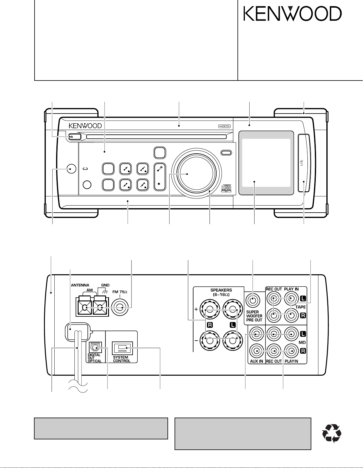
eject
on/standby
mode
stereo amplifier/tuner/CD RD-VH7
standby
timer
phones
tuning
band
demo
auto
/mono
p.call enter
input
stop
multi control
609 664 J1 J5 J2 J1
J2J3J4A1631
STEREO AMPLIFIER/TUNER/CD PLAYER
RD-VH7
SERVICE MANUAL
(VH-600/700)
Knob(EJECT) *
(K29-)
Indicator
(B12-0360-04)
Dressing panel *
(A21-)
Dressing panel
(A21-3761-02)
Dressing panel
(A21-3760-02)
Knob
(K29-7556-04)
Escutcheon
(B07-2452-13)
© 1999-6/B51-5551-00 (K/K) 3133
Panel
(A60-1647-11)
Front glass
(B10-3488-03)
Insulator assy
(J02-1444-24)
Knob(POWER)
(K29-7554-04)
Side plate
(A50-1326-02)
Power cord bushing
(J42-0083—05)
Oscillating module
(W02-1114-15)
AC power cord *
(E30-)
In compliance with Federal Regulations, following are reproductions of labels on, or inside the product relating to laser
product safety.
Lock terminal board
(E70-0052-05)
Screw terminal board
(E70-0111-05)
Rectangular receptacle
(E08-0311-05)
KENWOOD-Corp. certifies this equipment conforms to DHHS
Regulations No. 21 CFR 1040. 10, Chapter 1, Subchapter J.
DANGER : Laser radiation when open and interlock defeated.
AVOID DIRECT EXPOSURE TO BEAM.
Phono jack
(E63-0164-05)
Phono jack
(E63-1089-05)
Phono jack
(E63-1088-05)
*Refer to parts list on page 31.
Phono jack
(E63-1082-05)
TIMERSLEEP
POWER
REPEAT
123
456
789
+10 0 +100
RANDOM
P.MODE
CHECK
CLEAR
MUTE
CDMDTAPE
INPUT
AUTO/MONO TUNER/BAND
DISPLAY MEMORY TONE
REMOTE CONTROL UNIT
RC-RP0702
N.B.
TAPE MD
P.CALL
O.T.E.
V
O
L
U
M
E
C
O
N
T
R
O
L
TIMERSLEEP
POWER
REPEAT
123
456
789
+10 0 +100
RANDOM
P.MODE
CHECK
CLEAR
MUTE
CDMDTAPE
INPUT
AUTO/MONO TUNER/BAND
DISPLAY MEMORY
TA/NEWS PTY
TONE
REMOTE CONTROL UNIT
RC-RP0702E
N.B.
TAPE MD
P.CALL
O.T.E.
V
O
L
U
M
E
C
O
N
T
R
O
L
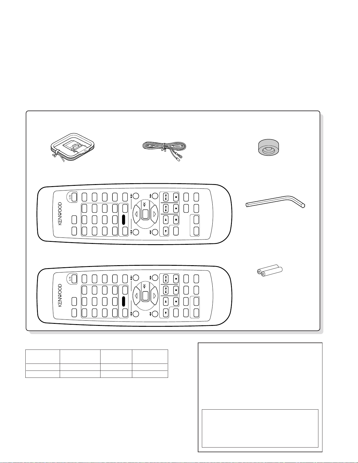
AM loop antenna (1)
(T90-0842-05)
Remote control unit (1)
(A70-1282-05) : RC-RP0702 Battery cover (A09-1148-08)
Remote control unit (1)
(A70-1283-05) : RC-RP0702E Battery cover (A09-1148-08)
Batteries (R6/AA) (2)
Replacement front feet (2)
(J02-0130-05)
Front feet replacement tool
(Allen wrench) (1)
(W01-0084-05)
FM indoor antenna (1)
(T90-0841-05)
RD-VH7
Operation to reset
The microcomputer may fall into malfunction (impossibility to operate, erroneous display, etc.)
when the power cord is unplugged while power is
ON or due to an external factor. In this case, execute the following procedure to reset the microcomputer and return it to normal condition.
RD-VH7
Unplug the power cord from the wall AC outlet
and, while holding the “7 stop” key depressed,
plug the power cord again.
÷If a CD has been loaded in the unit, it will be
ejected automatically.
÷ Please note that resetting the microcomputer
clears the contents stored in it returns it to condition
when it left the factory.
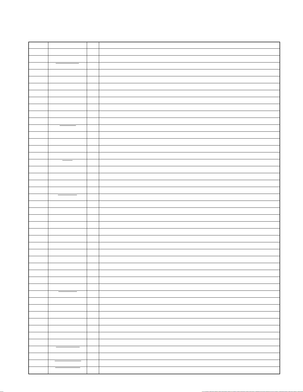
CONTENTS / ACCESSORIES
Contents
CONTENTS / ACCESSORIES ……………………………. 2
DISASSEMBLY FOR REPAIR………………………………3
BLOCK DIAGRAM………………………………………………4
CIRCUIT DESCRIPTION……………………………………..5
CD MECHANISM DESCRIPTION ……………………….11
ADJUSTMENT………………………………………………….14
Accessories
PARTS DESCRIPTIONS……………………………………15
PC BOARD ………………………………………………………16
SCHEMATIC DIAGRAM…………………………………….19
EXPLODED VIEW …………………………………………….29
PARTS LIST……………………………………………………..31
SPECIFICATIONS ………………………………..Back cover
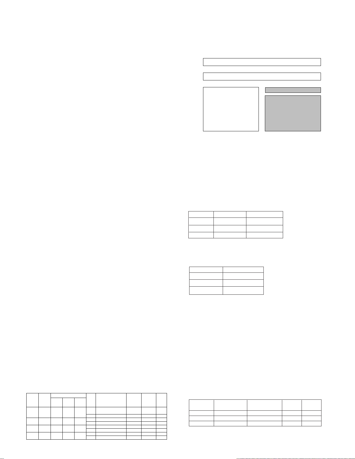
SPEAKER
System configuration
SYSTEM CD CASSETTE
NAME RECEIVER DECK
VH-600 RD-VH7 — LS-VH7
VH-700 RD-VH7 X-VH7 LS-VH7
2
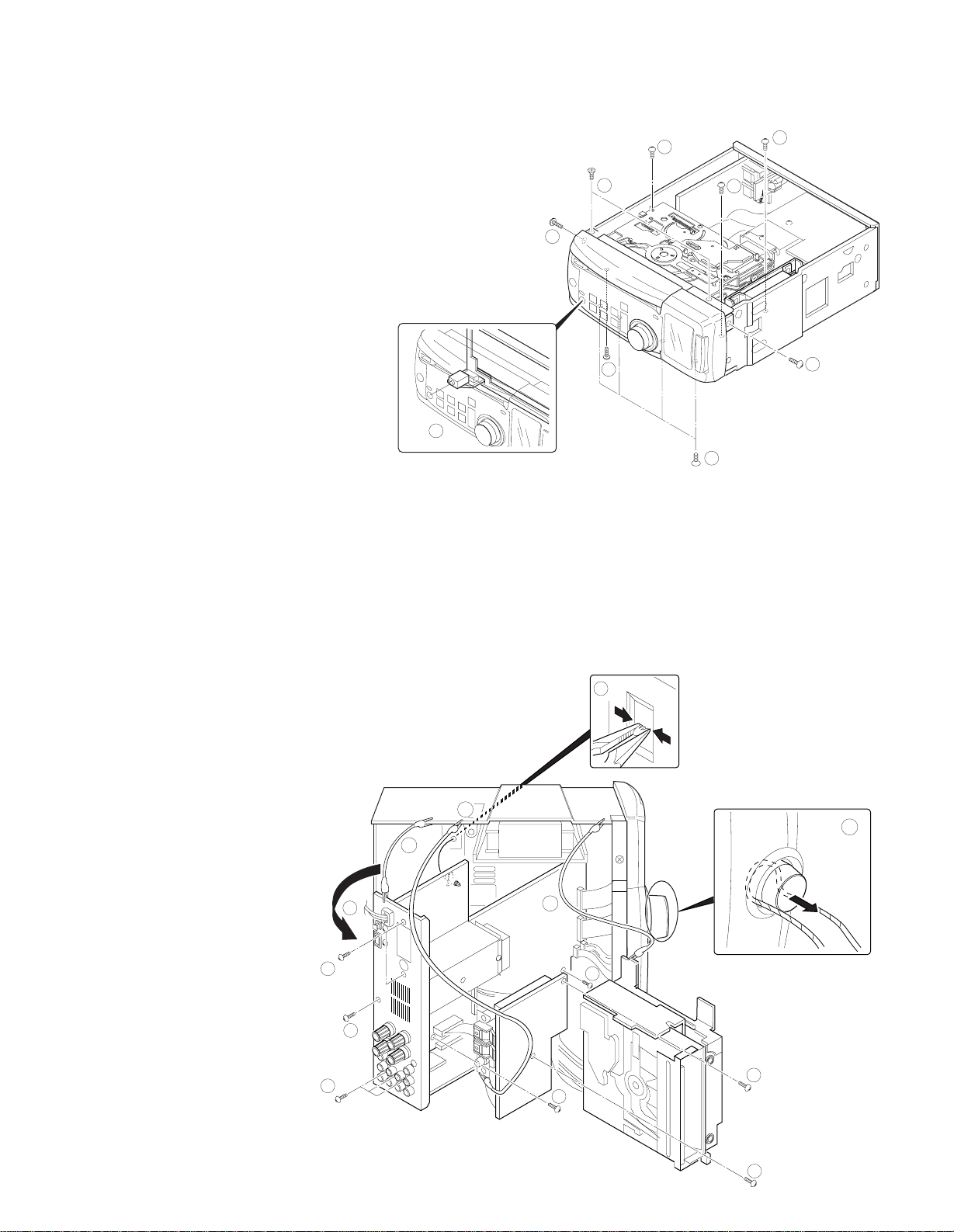
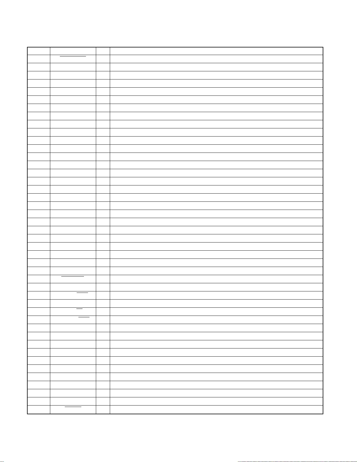
DISASSEMBLY FOR REPAIR
6
7
7
11
(X14)
(A/6)
MAIN
PCB
(X09)
8×3
5×3
5×2
5
9
10
10
10
6
(X09)
(B/4)
REMOVE CD MECHANISM
After remove insulator ass’y, then remove some LR side board.
Next remove the top and the bottom boards.
1) Remove the 6 screws1, then remove the front panel.
2) Remove the 6 screws23, then remove the CD mechanism.
When assemble the front panel, insert the phone jack with taking care4.
RD-VH7
ELECTRIC CHECK
After assemble the sub panel and the front panel.
1) Remove the 8 screws 5, 6, then remove PCB(X09:B/4), PCB(X14:A/6).
2) Remove the 2 screws 7, the 3 PC supports8, then remove the CD mechanism.
3) After assemble PCB (X09:B/4) on the main PCB with the rear panel. then connect GND between the rear panel , the antenna and the CD mechanism with 3 alligator clip wires(0).
★ Remove the MULTI CONTROL knob with a string(wires etc)-.
3
4
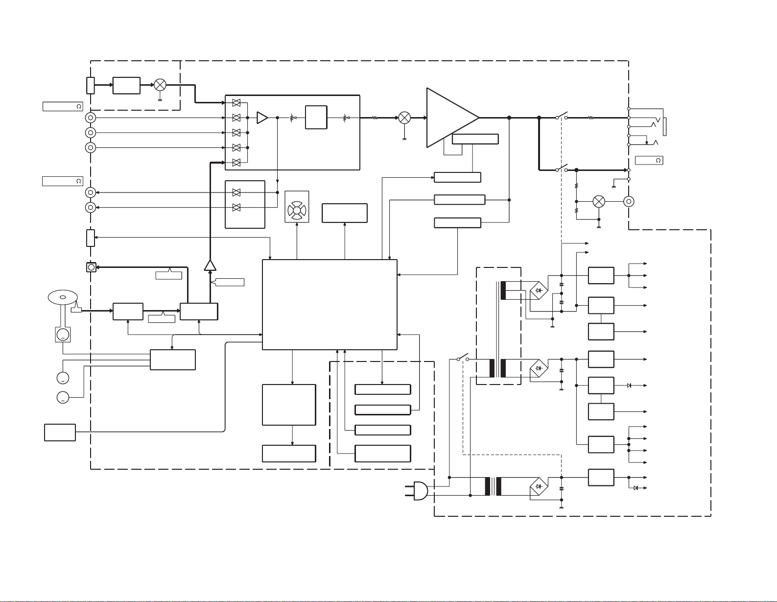
HEADPHONE
J3
12V
AVR
TUNER
PACK
AM,FM
ANTENNA
FAN
X-Y POSITION
N.B.
BASS
TRE.
THERMAL SW
BIAS Cont.
LEVEL SENSOR
PROTECTION
(TILT)SENSOR
STK499-090
MAIN AMP .
Cont.
SYSTEM
TAPE PLAY
MD REC
TAPE REC
T.MUTE
J1
TONE
SELECTOR
REC OUT
A1
J1
Q1-3
IC2
ATT
INPUT
VOLUME
MASTER
IC3
BU4066BCF
A.MUTE
IC1
K3
K2
J5
J2
Q1,2
Q7,8
IC8
Q5,6,10
PH1-4
M30622MC-570FP
MAIN u-COM
LED
TACT KEY
M.C/ENCODER
REMOCON
SENSOR
S2-13
S1
A2
D11,12
DISPLAY u-COM
HD6433297A17F
LCD ASS’Y
IC4
IC5
-13V
AVR
-10V
AVR
FAN+B
AVR
+6.3V
AVR
+5V
AVR
+5.6V
AVR
+5.6V
AVR
MUTE
Q12
CD MECHA DRIVER
FAN
LCD
MUTE
BIAS CHANGE
TUNER PACK
AUDIO
CD
MECHA SENSOR
LCD
DISPLAY u-COM
LED
u-COM
AMP. +B
AMP. -B
Q20
Q33
Q17
Q23-26
IC10
IC6
Q22
Q28
DSP/DAC
SERV0
RF AMP
5ch BTL
DISC
SENSOR
D10
D11
D18
K1
T1
BACK UP TRANS.
MAIN TRANS.
DIGITAL
DIGITAL
ANALOG
IC400
IC401
IC402
M
PICKUP
M
MOTOR
DISC
SLED
MOTOR
D1-4,Q1-4
S1
CD SLOT IN
MECHANISM (CDM-34)
200mV/100
REC OUT
200mV/47K
INPUT
9.5V/6
SP.OUTPUT (2CH)
S.W. OUT
SPEAKER
LC75396NE
IC403
A4
MD PLAY
AUX
OPTICAL
OUT
(+5V)
RDS
AC IN
LOADING
MOTOR
M
+
+
+
+
A-D
RD-VH7
(X14) (X09)
(X14)
RD-VH7
BLOCK DIAGRAM
CIRCUIT DESCRIPTION
RD-VH7
1. INITIAL SETTING
1-1 INITIAL CONDITIONS
(1) AMP
POWER OFF
PROTECTION NO DETECTED
MUTE OFF
SELECTOR TUNER
VOLUME 15
BALANCE CENTER
NB 2
BASS 0
TREBLE 0
MD INPUT 0 (-6dB)
TAPE INPUT 0 (-6dB)
AUX INPUT 0 (-6dB)
MULTI WINDOW AUTO
(2) TUNER
BAND FM
Pch MEMORY REFER TO (5)
LAST Pch – –
LAST FREQ. LOWER LIMIT VALUE OF
EACH BANDS
AUTO/MONO AUTO
AUTO PRESET (MEMORY) –
E ON THRUST RECEIVING MODE
OFF
RDS DISPLAY PS
(3) CLOCK, TIMER
CLOCK STOP, AM 12:00
PROG. 1,2
ON TIME AM12:00
OFF TIME AM12:00
PLAY MODE PLAY
SOURCE TUNER
Pch 01ch
REC MODE TAPE
O. T. T. OFF (AM7:00)
TIMER OPERATION MODE OF F
SLEEP TIMER OFF(5)
A. P. S. OFF
(4) CD
PLAY MODE TRACK
REPEAT OFF
RANDOM OFF
OPERATION MODE STOP
TIME DISPLAY SINGLE TIME
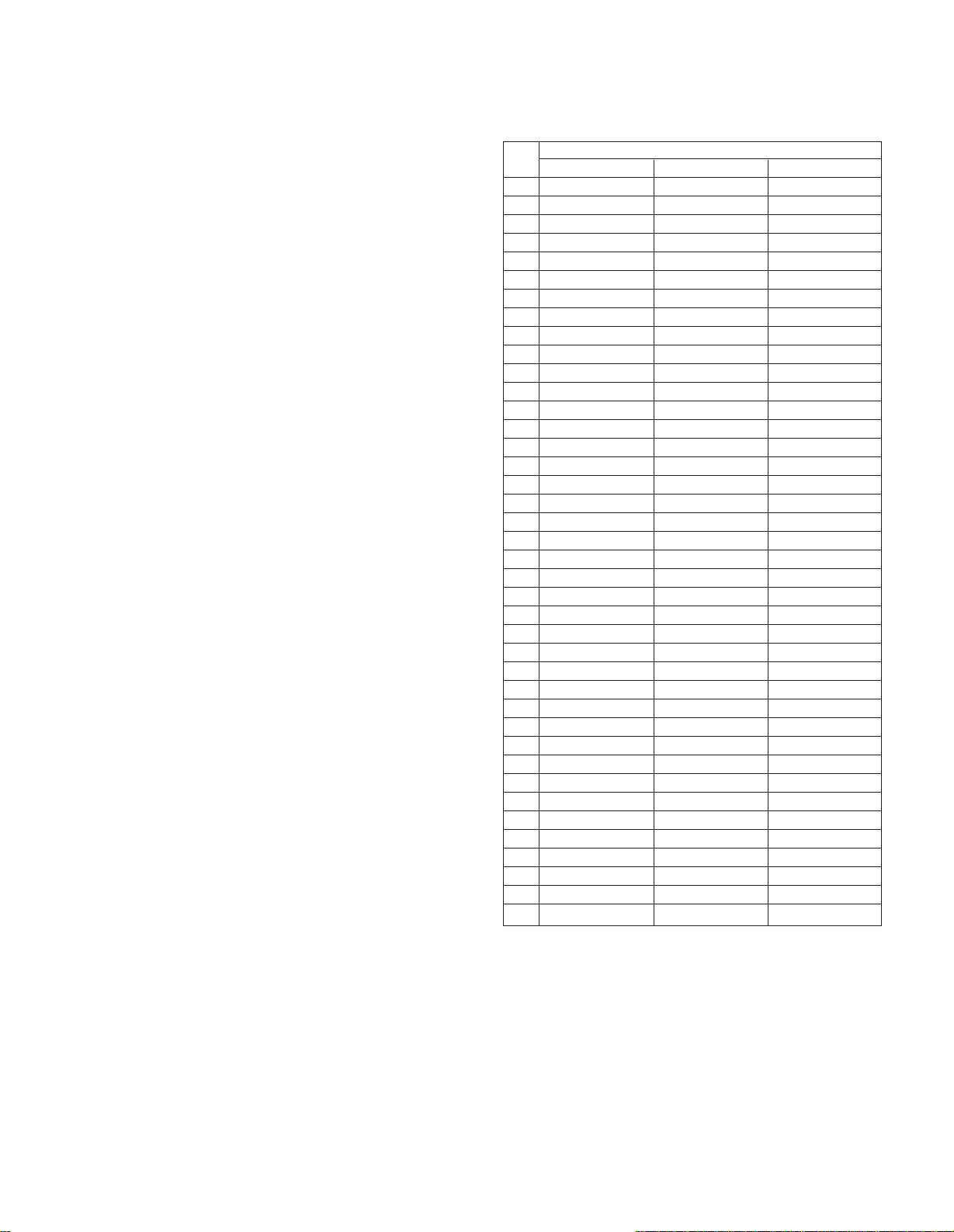
(5) TUNER PRESET FREQUENCY
ch
E1 K1 E3
1 FM 97.5MHz FM 97.5MHz FM 97.5MHz
2 FM 87.5MHz FM 87.5MHz FM 87.5MHz
3 FM 89.1MHz FM 89.1MHz FM 89.1MHz
4 FM 108.0MHz FM 108.0MHz FM 108.0MHz
5 FM 90.0MHz FM 90.0MHz FM 90.0MHz
6 FM 87.5MHz FM 87.5MHz FM 87.5MHz
7 FM 87.5MHz FM 87.5MHz FM 87.5MHz
8 FM 87.5MHz AM 1610KHz FM 87.5MHz
9 AM 1602KHz AM 1700KHz AM 1602KHz
10 AM 999KHz AM 1000KHz AM 999KHz
11 AM 630KHz AM 630KHz AM 630KHz
12 AM 1440KHz AM 1440KHz AM 1440KHz
13 FM 106.0MHz FM 106.0MHz FM 106.0MHz
14 AM 531KHz AM 530KHz AM 531KHz
15 FM 87.5MHz FM 87.5MHz FM 87.5MHz
16 FM 98.0MHz FM 98.0MHz FM 98.0MHz
17 FM 98.5MHz FM 98.5MHz FM 98.5MHz
18 FM 87.5MHz FM 87.5MHz FM 87.5MHz
19 AM 990KHz AM 990KHz AM 990KHz
20 FM 97.7MHz FM 97.4MHz FM 97.7MHz
21 AM 531KHz AM 530KHz AM 531KHz
22 FM 87.5MHz FM 87.5MHz FM 87.5MHz
23 FM 87.5MHz FM 87.5MHz FM 87.5MHz
24 FM 87.5MHz FM 87.5MHz FM 87.5MHz
25 FM 87.5MHz FM 87.5MHz FM 87.5MHz
26 FM 87.5MHz FM 87.5MHz FM 87.5MHz
27 FM 87.5MHz FM 87.5MHz FM 87.5MHz
28 FM 87.5MHz FM 87.5MHz FM 87.5MHz
29 FM 87.5MHz FM 87.5MHz FM 87.5MHz
30 FM 106.0MHz FM 106.0MHz FM 106.0MHz
31 FM 87.5MHz FM 87.5MHz FM 87.5MHz
32 FM 87.5MHz FM 87.5MHz FM 87.5MHz
33 FM 87.5MHz FM 87.5MHz FM 87.5MHz
34 FM 87.5MHz FM 87.5MHz FM 87.5MHz
35 FM 87.5MHz FM 87.5MHz FM 87.5MHz
36 FM 87.5MHz FM 87.5MHz FM 87.5MHz
37 FM 87.5MHz FM 87.5MHz FM 87.5MHz
38 FM 87.5MHz FM 87.5MHz FM 87.5MHz
39 FM 108.0MHz FM 108.0MHz FM 108.0MHz
40 AM 999KHz AM 1000KHz AM 999KHz
TUNER DESTINATION
2. BACKED UP ITEMS
AC POWER OFF
(1) AMP
POWER BACK UP
PROTECTION CANCELLED
MUTE OFF
SELECTOR BACK UP
VOLUME BACK UP
BALANCE BACK UP
5
RD-VH7
CIRCUIT DESCRIPTION
NB 2
BASS BACK UP
TREBLE BACK UP
MD INPUT BACK UP
TAPE INPUT BACK UP
AUX INPUT BACK UP
MULTI WINDOW BACK UP
(2) TUNER
BAND BACK UP
Pch MEMORY BACK UP
LAST Pch BACK UP
LAST FREQ. BACK UP
AUTO/MONO BACK UP
AUTO PRESET (MEMORY) BACK UP
E ON THRUST RECEIVING MODE
BACK UP
RDS DISPLAY PS
(3) CLOCK, TIMER
CLOCK POWER FAILURE MODE
PROG. 1, 2
ON TIME BACK UP
OFF TIME BACK UP
PLAY MODE BACK UP
SOURCE BACK UP
Pch BACK UP
REC MODE BACK UP
O. T. T. BACK UP
TIMER OPERATION MODE BACK UP
SLEEP TIMER OFF
A. P. S. BACK UP
(4) CD
PLAY MODE TRACK
REPEAT OFF
RANDOM OFF
OPERATION MODE STOP
TIME DISPLAY SINGLE TIME
3. CONDITIONS ACCORDING TO THE
DESTINATION
( ) SIGNIFIES PIN NUMBER OF u-COM(X09, IC4)
u-COM
DESTI-
DESTI-
NATION
NATION
J J 0 1 0 FM 76.0MHz~ 87.5MHz 100kHz -10.7MHz 25kHz
K,P K1 0 0 0 FM 87.5MHz~108.0MHz 100kHz +10.7MHz 25kHz
M E1 0 0 1 FM 87.5MHz~108.0MHz 50kHz +10.7MHz 25kHz
E,T E3 1 1 0 FM 87.5MHz~108.0MHz 50kHz +10.7MHz 25kHz
6
RDS AM 531kHz~1602kHz 9kHz +450kHz 9kHz
DSW
2
(72PIN)1(71PIN)0(70PIN)
RECEIVING
BAND
FREQUENCY RANGE SPACE
87.5MHz~108.0MHz 50kHz -10.7MHz 25kHz
AM 531kHz~1629kHz 9kHz +450kHz 9kHz
AM 530kHz~1700kHz 10kHz +450kHz 10kHz
AM 531kHz~1602kHz 9kHz +450kHz 9kHz
CHANNEL
IF RF
4. LCD INDICATION
PARTS OFF LCD INDICATION
A PART
B PART
C PART
D PART
E PART
PROG 1 2
OTT APS
RADIO T
5. How to Set the Test Modes
5-1 AUX(MD/TAPE/AUX)
Setting: Insert the power cord to the wall outlet with
pressing the MODE key.
Cancel: Press any key of operation.
A part A of display shows destination(✽).
«standby» LED lights orange and green color alternately
in this test mode.
A part E of display shows as follows after selecting MD
mode.
selector display E display A
MD MD##TEST ✽-TYPE####
TAPE TAP#TEST ✽-TYPE####
AUX AUX#TEST ✽-TYPE####
5-1-1 Display Contrast Setting
Display contrast is available in LED and all segments of
display lighting
Contrast is set to initialization if cancel test mode.
key remarks
FF contrast min.
skip up initialization
play/pause contrast max.
5-1-2 Mute Setting
Muting function is available by pressing AUTO/MONO
key.
5-1-3 AUX IN Level Setting
Select the level of aux input from +3, 0, or -6 by pressing
the FB key.
Multi control knob is available for same setting after
mode key is pressed.
5-1-4 Noise Blanker Setting
Select the level of NB from NB1,NB2 or NB OFF by
pressing the SKIP DOWN key.
5-1-5 BASS/TREBLE setting
Select the level of tone from tone max, tone flat or tone
min by pressing the BAND key.
Display shows as follows.
display A display B
tone max. BASS/TER## #######MAX +8 +8
tone min. BASS/TER## #######MIN -8 -8
tone flat BASS/TER## ####CENTER 0 0
Multi control knob is available for same setting after
mode key is pressed.
#=space
bass treble
value value
CIRCUIT DESCRIPTION
RD-VH7
5-1-6 Balance Setting
Select the level of balance from L-ch, max, R-ch max or
center by pressing the MODE key.
Multi control knob is available for same setting after
mode key is pressed.
5-2 TUNER
Setting: Insert the power cord to the wall outlet with
pressing the BAND key.
Cancel: Press any key of operation.
A part E of display shows RADIO T.
«standby» LED lights orange and green color alternately
in this test mode.
5-2-1 Dimmer Setting
Dimmer is available in LED and all segments of display
lighting
Select the on/off of dimmer from dimmer on or dimmer
off by pressing the CD/PLAY/PAUSE key.
Dimmer is set to OFF if cancel test mode.
5-2-2 P.CALL Setting
Select the step of p.call from 10,20, — 40 or 01(10steps)
by pressing the MODE key.
5-2-3 P. CALL Up/Down Setting
This setting is available by P.CALL UP/DOWN key.
5-2-4 Normal Mode (AUX/TUNER)
This setting is available by pressing MODE key for 1.5
secs .
CD eject works except tuner mode.
5-3 Sub Clock Oscillation Check
Setting: Insert the power cord to the wall outlet with
pressing the INPUT key.
Cancel: Press any key of operation. However continue
tuner test mode.
Display lights if oscillation and period are ok. Display
shows ERR1(oscillation) or ERR2(period) and stop to
check after 5 time checks.
5-4 CD
Setting: Insert the power cord to the wall outlet with
pressing the PLAY key.
Cancel: Press any key of operation. However a part B of
display is only cancel.
A part A of display shows mechanism sensors. Disc
loading sensor/8cm sensor/12cm sensor/down switch in
order. Display shows «-» at first time.
A part B of display shows CD-TEST LED is blanking.
5-4-1 Mechanism Sensor Check
Display shows from «-» to «0» or «x» after loading the
disc. «0» means sensor works.
«x» not works.
5-4-2 Adjusting
key description
CD PLAY/ tracking servo on/off
PAUSE display B shows 05✽✽:✽✽ if servo on
display B shows 03—:— if servo off
skip up horizontal or vertical position choice
display B shows 05V✽✽:✽✽ in
horizontal mode
(servo gain and tracking bias)
5-4-3 Pickup Movement
key description
FF pickup travels outwards and display B
shows OUTSIDE.
FB pickup travels inwards and display B
shows INSIDE.
5-4-4 Initialization in Test Mode
CD stop to playback. Display B shows 0100:00
5-5 Factory Test Check
5-5-1 Initial Operation
Setting: Insert the power cord to the wall outlet with
pressing the AUTO/MONO key.
Cancel: Turn power off.
1. Check sub clock oscillation. Display lights for 2 secs. If no
problem.
2. Display A shows destination.
3. Display A shows sensor’s condition with H or L after any
key is pressed.
5-5-2 Display Check
Display’s dots light on or off by pressing MODE key.
Back light is always on.
5-5-3 Slot Check
key description
FF slot in operation. Display B shows LOAD
FB slot out operation. Display B shows UNLOAD.
6. Initialization
Setting: Insert the power cord to the wall outlet with
pressing the STOP key.
Initialize amplifier section(preset,time reset and RAM)
after CD mechanism initialization.
Turn unit to standby mode.
Display shows INITIALIZE for check time.
Display shows CD EER if any trouble.
7. Cancel of Test Mode
Initialized and cancel test mode if pulling out power cord.
Not initialized and cancel test mode if the power switch
turns off.
Turn normal mode if pressing STOP key in stop
condition of CD test mode.
8. Common Operation in Test Mode
1. Volume level is 40 at every test mode start up.
2. No muting with switching test mode. But muting-on if
power switch on/off.
3. AUX test mode is available for selecting MD,TAPE, or
AUX
4. Initialize setting value or condition if pull out the power
cord.
5. AUX IN LEVEL is initialized to +3(0dB).
6. Input key is available for switching test mode
item,tuner,cd, MD, tape and aux.
7
RD-VH7
CD ASP
LA9241M
CD MECHA.
CDM-34
TUNER UNIT
(RDS DECODER)
E/T ONLY
RELAY (PWER, SP, HP)
DISPLAY u-COM
HD6433297A17F
SL16
LCD DRIVER
SED1565
LCD
REM BACK UP
FAN
BIAS
MUTING
PROTECTION
REC OUT SEL
LED
KEY
CD DSP
LC78628E
SYSTEM IC
LC75396NE
X09, IC400 X09, IC401 X09, IC2
X09, IC4
X09, IC5
M30622MC-570FP
ENCODER
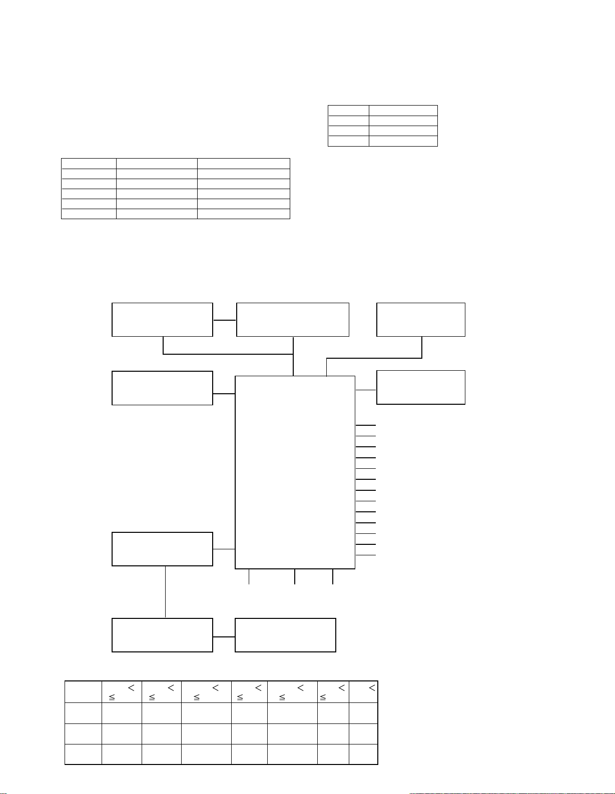
AUDIO LEVEL
DESTINATION
TILT SENSOR
HEADPHONES DETECTOR
VOLTAGE
0.000
1.061
1.061
1.726
1.726
2.437
2.437
3.156
3.156
3.827
3.827
4.586
4.586
KEY1
89PIN
MODE POWER KEY
OFF
KEY2
90PIN STOP
SKIP
DOWN
PLAY/PAUSE INPUT BAND KEY
OFF
KEY3
91PIN
SKIP
UP EJECT
TUNING
UP
TUNING
DOWN
AUTO/MONO KEY
OFF
CIRCUIT DESCRIPTION
9. Common Operation in AUX/TUNER Test
9-2 FAN Operation
Mode
9-1 Bias and Main Volume Level
Set unit to aux or tuner test mode.
Select the proper value with CD PLAY/PAUSE or CD
STOP key.
volume bias display D
0 pure A low PURE#A#L
1 pure A low PURE#A#L
20 pure A mid PURE#A#M
40 pure A high PURE#A#H
80 pure B low PURE#B#L
Multi control knob is available for same setting after
mode key is pressed.
10. MICROPROCESSOR ; M30622MC-570FP(X09,IC4)
10-1 MICROPROCESSOR PERIPHERY BLOCK DIAGRAM
Display C shows fan condition.
FAN Display C
off FAN#OFF#
low FAN#low#
high FAN#Hi##
KEY MATRIX
* REFERENCE VOLTAGE: 5.0V
8
CIRCUIT DESCRIPTION
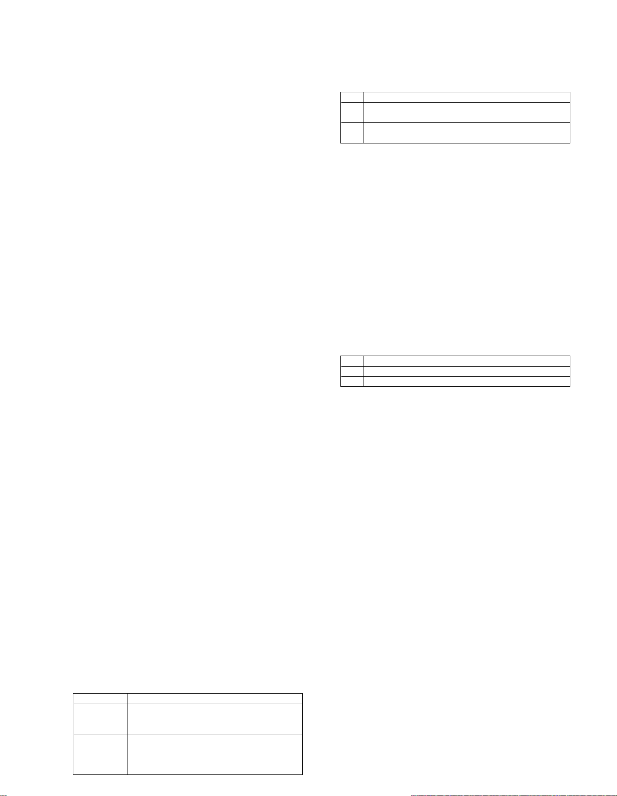
10-2 MICROPROCESSOR PIN DESCRIPTION
Pin No. Pin Name I/O Descriptin
1 RELAY HP O Headphones relay control terminal.
2 RELAY SP O Speaker relay control.
3 DISP_RST O Reset for communication between display u-COM and u-COM(IC4).
4 DISP CE O Chip enable for communication between display u-COM and u-COM(IC4).
5 DISP OUT O Data out for communication between display u-COM and u-COM(IC4).
6 DISP IN I Data In for communication between display u-COM and u-COM(IC4).
7 DISP CLK O Clock for communication between display u-COM and u-COM(IC4).
8 BYTE I Connected to ground.
9 CNVSS I Connected to ground.
10 XCIN I Clock (32.768kHz).
11 XCOUT O Clock (32.768kHz).
12 RESET I Reset terminal of microprocessor.
13 XOUT O Main clock.
14 VSS — Ground.
15 XIN I Main clock.
16 VCC — Power supply(+5V).
17 NMI I Connected to power supply(+5V).
18 REMOCON I Remocon signal Input.
19 DQSY I Text data reading permission signal Input.
20 WRQ I Q code reading permission signal Input.
21 NC O Unused.
22 DIMMER O LCD back light dimmer.
23 COIN O Output terminal of u-COM data.
24 TGL I Change-over for tracking gain.
25 NC O Unused.
26 FSEQ I EMF synchronism signal Input.
27 NC O Unused.
28 CQCK O Clock output.
29 SQOUT I Sub code Q Input.
30,31 NC O Unused.
32 SRDT I Text data Input.
33 SCLK O Clock for text data.
34 SDA O Unused.
35 SCL O Unused.
36,37 NC O Unused.
38 CD_RST O Reset signal output.
39 DRF I Focus OK signal Input.
40 RWC O Read/write control output.
41 SL- O Moves the sled slightly toward the Inner position of disc.
42 SL+ O Moves the sled slightly toward the outer position of disc.
43 LOADING O Change-over for mechanism loading(+/-).
44 LOAD MUTE O Change-over for mechanism loading(ON/OFF).
45 NC O Unused.
46 LOAD_SW I Detection terminal for disc.
47,48 NC O Unused.
49 12DISC_SW I 12cm disc detection terminal.
50 DOWN_SW I Control port of down motor for mechanism.
RD-VH7
9
RD-VH7
CIRCUIT DESCRIPTION
Pin No. Pin Name I/O Descriptin
51 BACK_UP I Detection port for backup mode.
52 NC O Unused.
53,54 ENC1/2 I Rotary encoder1/2 Input.
55 SL16 DATA I/O SL16 data input/output.
56 SL16 BUSY I/O SL16 busy input/output.
57 STBYLED O LED3 standby(red).
58 ON LED O LED2 standby(grn).
59 EJECTLED O LED1 (eject).
60 MD REC SEL O Control terminal for MD rec.
61 TAPE REC SEL O Control terminal for TAPE rec.
62 VCC — Power supply.
63 TILT SENS I Detection terminal of FL lenght and breadth conditions.
64 VSS — Ground.
65 NC O Unused.
66 A-MUTE O Audio muting control.
67 -10V CONT. O Control terminal for LCD power supplly(-10V).
68 BIAS HIGH O Bias control(HIGH).
69 BIAS MID O Bias control(MID).
70~72 DSW0~2 I Discrimination of model destination(SW0~2).
73 STEREO I Detection terminal of stereo signal for TUNER.
74 SD I Detection terminal of SD signal for TUNER.
75 RDS CLK I RDS clock Input.(E/T version only)
76 RDS DATA I RDS data Input.(E/T version only)
77 PLL DO I PLL IF count Input.
78 CE O Chip enable to LC75396(IC2) and LC72131(tuner pack IC2).
79 DATA O Data to LC75396(IC2) and LC72131(tuner pack IC2).
80 SCLK O Clock to LC75396(IC2) and LC72131(tuner pack IC2).
81 T_MUTE O TUNER muting control.
82 (EMPHASIS) O DE-EMPHASIS control.
83 CD ON/OFF O Unused.
84 NC O Unused.
85 FAN _H/L O Fan H/L change-over.
86 FAN ON/OFF O Fan ON/OFF control.
87 POWER RE O Power relay control. H = ON L = OFF
88 PROTECT I Detection terminal of protection. H =protection ON
89~91 KEY1~3 O Key A/D Input 1~3.
92,93 PT4,3 I Detection terminal of 8cm disc.
94 A LEVEL I Audio level Input(A/D).
95 RDS SLEVEL I RDS signal level Input(A/D). (E/T version only)
96 AVSS — A/D ground.
97 PROTECT TEMP I Detection terminalfor temperature compensating.
98 VREF — A/D reference voltage.
99 AVCC — A/D power supply(+5v).
100 HP_IN I Headphones detection terminal.
10
Loading…
-
Страница 1
INSTRUCTION MANUAL KENW OOD CORPORA TION AMPLIFIER-TUNER/CD PLA YER CASSETTE T APE DECK RD-VH7 X-VH7 DIGITAL AUDIO COMPACT COMPACT TEXT B60-4280-10 Before installation, be sure to read “System configuration” and “Installa- tion” in this manual to ensure correct installation. 0 , ! This instruction manual is used to describe multiple models […]
-
Страница 2
RD-VH7/X-VH7 (EN) 2 Before applying power Before applying power Units are designed for operation as follows. U.S.A. ………………………………………………………………….. AC 120 V only The marking of products using lasers (Except for some areas) EUROPE & U.K. …………………………………………………… AC[…]
-
Страница 3
RD-VH7/X-VH7 (EN) 3 Before applying power Contents Before applying power ………………………………… 2 Introduction ………………………………………………….. 6 Special features ………………………………………………………. 7 IMPORTANT SAFEGUARDS ………………………….. 8 System configuration[…]
-
Страница 4
RD-VH7/X-VH7 (EN) 4 Before applying power Accessories Accessories supplied with RD-VH7 Accessories supplied with X-VH7 (optional) AM loop antenna (1) Audio cord (2) Remote control unit (1) Batteries (R6/AA) (2) O.T.E. Spacer for stacked installation (1) System control cord (1) Replacement front feet (2) The demonstration consists of sequential swit[…]
-
Страница 5
RD-VH7/X-VH7 (EN) 5 Before applying power Unpacking Unpack the unit carefully and make sure that all accessories are put aside so they will not be lost. Examine the unit for any possibility of shipping damage. If your unit is damaged or fails to operate, notify your dealer immediately. If your unit was shipped to you directly, notify the shipping c[…]
-
Страница 6
RD-VH7/X-VH7 (EN) 6 Before applying power VH series Thank you for purchasing an VH series product. The VH series system components include the amplifier-tuner/ CD player, MD recorder and cas- sette deck, so the user can select and purchase desired models among them. By connecting some of these components using KENWOOD system control cords, convenie[…]
-
Страница 7
RD-VH7/X-VH7 (EN) 7 Before applying power Special features ❑ Amplifier designed with emphasis on sound quality (Pure A amplification) The Pure A class reproduction mode is built in to improve the sound quality during low-level listening. The sound quality is switched automatically into AB-class as the volume level is de- creased to ensure transpa[…]
-
Страница 8
RD-VH7/X-VH7 (EN) 8 Before applying power 7. Heat – The appliance should be situated away from heat sources such as radiators, heat registers, stoves, or other appliances (including amplifiers) that produce heat. 8. Electric shock – Care should be taken so that objects do not fall and liquid is not spilled into the enclosure through openings. I[…]
-
Страница 9
RD-VH7/X-VH7 (EN) 9 Before applying power IMPORTANT SAFEGUARDS 14. Abnormal smell – If an abnormal smell or smoke is detected, immediately turn the power OFF and unplug the appliance from the wall outlet. Contact your dealer or nearest service center. 15. Damage requiring service – The appliance should be serviced by qualified service personnel[…]
-
Страница 10
RD-VH7/X-VH7 (EN) 10 System configuration, Installation System configuration, Installation System configuration The VH series system components can be installed either vertically on the sides (lengthwise) or horizon- tally by stacking one component on another. If you purchased the RD-VH7 alone, install it properly by also referring to the instructi[…]
-
Страница 11
RD-VH7/X-VH7 (EN) 11 System configuration, Installation When the components are to be installed horizontally for stacking, be sure to use the spacer for stacked installation which is provided with each component unit. The front feet attached at the factory to each component unit of this series can be replaced with the pro- vided replacement feet. I[…]
-
Страница 12
RD-VH7/X-VH7 (EN) 12 System connection 1. Connection of antenna Connect the antenna as shown in the figure. Do not plug the power cord into a wall AC outlet until the connection has been completed. AM loop antenna The supplied antenna is for indoor use. Place it as far as possible from the main system, TV set, speaker cords and power cord, and set […]
-
Страница 13
RD-VH7/X-VH7 (EN) 13 System connection Malfunction of microcomputer If operation is not possible or errone- ous display appears even though all connections have been made prop- erly, reset the microcomputer refer- ring to “In case of difficulty”. I 2. Connection of audio cord Here, connection of separately sold components also will be explained[…]
-
Страница 14
RD-VH7/X-VH7 (EN) 14 System connection 3. Connection of system control cord 1. Be sure to insert all connection cords securely. If their connections are imperfect, the sound may not be pro- duced or noise may interfere. 2. Before plugging or unplugging a connection cord, be sure to unplug the power cord from the wall AC outlet. If connection cords […]
-
Страница 15
RD-VH7/X-VH7 (EN) 15 System connection 4. Connection of speakers Connect the speakers as shown in the figure. Do not plug the power cord into a wall AC outlet until the connection has been completed. Super woofer (SW-500) (optional) Extremely low frequency sound is played back power- fully. Speaker (Right) (6-16 Ω ) Speaker (Left) (6-16 Ω ) ÷ […]
-
Страница 16
RD-VH7/X-VH7 (EN) Controls and indicators 16 Main Unit Amplifier-tuner/ CD player (RD-VH7) Controls and indicators Cassette deck (X-VH7) recording function indicator Dolby NR B-type rev.m ode crls pause C-type reverse forward direction eject standby on/standby fwd rev rec /arm crls stop pause tape loading mechanism rev.mode Dolby NR auto reverse ca[…]
-
Страница 17
RD-VH7/X-VH7 (EN) Controls and indicators 17 9 “ 7 stop” key When power is OFF (standby): Press to display the time of the day for 5 seconds. ¡ During CD playback: Press to stop playback. ¶ 0 “enter, 6 ” key During operation mode setting: Press to set an entry. When power is OFF (standby): Press to turn the system power ON and start CD pl[…]
-
Страница 18
RD-VH7/X-VH7 (EN) Controls and indicators 18 Remote control Unit When the system control cord is connected, this remote control can be used to operate the entire system. The keys on the remote control unit with the same names as on the main unit have the same function as the keys on the main unit. Model: For U.K. and Europe …………….. RC-RP0[…]
-
Страница 19
RD-VH7/X-VH7 (EN) Controls and indicators 19 4 POWER key “ POWER” key ™ , p , E Press to switch the power of the amplifier-tuner/CD player (RD-VH7) ON and OFF (standby). When system components are connected through system control cords, press to turn the entire system power ON and OFF. This key is also used in timer programming. 5 CD play mod[…]
-
Страница 20
RD-VH7/X-VH7 (EN) Controls and indicators 20 Operation of remote control unit Plug the power cord into a power outlet and press the “ POWER” key on the remote con- trol unit to switch the power ON. Then press the key of the function you want to control. Operation ÷ When pressing more than one remote control keys successively, press the keys se[…]
-
Страница 21
RD-VH7/X-VH7 (EN) Controls and indicators 21 Example for adjusting at 12:30PM 1 Adjust the figure of hour by rotating the “multi control” knob. 2 Press the “enter” key. 1 Adjust the figure of minute by rotating the “multi control” knob. 2 Press the “enter” key. Enter the minute. Enter the hour. This unit incorporates a clock functio[…]
-
Страница 22
RD-VH7/X-VH7 (EN) Hearing sound 22 When CD has been se- lected. Volume display 1. Switching the power ON (OFF). Hearing sound 3. Volume adjustment. 2. Selecting the desired output. Muting the sound temporarily When the “on/standby” key is pressed while the power is ON, the power will be switched OFF. ÷ The entire system can be switched ON and […]
-
Страница 23
RD-VH7/X-VH7 (EN) Hearing sound 23 Muting the sound temporarily ÷ Press again to resume the original volume. ÷ This is also cancelled when the volume is adjusted. Bass and treble compensation (N.B.: Natural Bass circuit) Each press switch the modes as follows. “N.B.1” ….. The high and the low range are compensated according to the volume (e[…]
-
Страница 24
RD-VH7/X-VH7 (EN) Hearing sound 24 Input level adjustment RD-VH7 mode multi control enter BALANSET +3 MD P INPUT The input levels of MD, TAPE and AUX can be adjusted independently. This is intended to mini- mize the difference between input levels from different input sources when these are switched over between them. 1 Select the input source to b[…]
-
Страница 25
RD-VH7/X-VH7 (EN) Hearing sound 25 The contrast of the LCD display on the amplifier- tuner/ CD player can be switched as desired. 1 Press the “mode” key. 2 Rotate the “multi control” knob to select “CONTRAST SET ?”, then press the “enter” key. 3 Select the desired brightness (display den- sity) by rotating the “multi control” kn[…]
-
Страница 26
RD-VH7/X-VH7 (EN) 26 Playback of CD ÷ No adapter is necessary to play an 8 cm CD. ÷ Discs with certain special designs (transparent discs, etc.) may not be able to be ejected by the first press. In such a case, try holding the “ 0 eject” key depressed. If a disc cannot be inserted smoothly, try pushing it with a light force; this may promote […]
-
Страница 27
RD-VH7/X-VH7 (EN) 27 Playback of CD ÷ Each press pauses and plays the CD alternately. To pause playback ÷ Playback starts from the position where the key is released. To fast forward and backward Skipping tracks ÷ The track in the direction of the button pressed is skipped, and the selected track will be played from the beginning. ÷ When the ?[…]
-
Страница 28
RD-VH7/X-VH7 (EN) 28 Playback of CD Time display on CD player (Remote control unit only) Each press of the “DISPLAY” key switches the displayed information items one after another. ÷ Only the time information on the track being played can be displayed during single-track repeat playback or random playback. ÷ When the total playing time of the[…]
-
Страница 29
RD-VH7/X-VH7 (EN) 29 Playback of CD Recording a HDCD disc Use the following procedure to record digitally the digital input from a CD recorded in the HDCD for- mat. To make this possible, it is required to select whether the data from the HDCD disc is to be output as a HDCD-decoded 20-bit signal or as an ordinary 16-bit signal. (HDCD 20-bit digital[…]
-
Страница 30
RD-VH7/X-VH7 (EN) 30 Playback of CD Listening in the desired sequence (program playback) Desired tracks in a disc can be programmed in the desired order and played back. (Max. 32 tracks) 1 Check that the CD player is in the stop mode. 2 3 Light the “PGM” indicator. Enter track Nos. in the order you want to play them. 4 Start playback. Select th[…]
-
Страница 31
RD-VH7/X-VH7 (EN) 31 Playback of CD To add a track to the program (Remote control unit only) 1 Select the track number to be added using the numeric keys. 2 Press the “P. MODE” key. ÷ Up to 32 tracks can be programmed. When “PGM FULL” is displayed, no more tracks can be pro- grammed. ÷ When a track No. is entered, the track will be added […]
-
Страница 32
RD-VH7/X-VH7 (EN) 32 Playback of CD Select the “CD” input. Repeated playback To repeat a disc 1 If the PGM indicator is lit, press the “P.MODE” key to turn it off. 2 Press the “REPEAT” key repeatedly until “ALL REP.” is displayed. 3 Press the “CD 6 ” key. Desired track(s) or disc can be played repeatedly. To repeat selected trac[…]
-
Страница 33
RD-VH7/X-VH7 (EN) 33 Playback of CD To select another track in the middle of play- ing one To cancel random playback Playing tracks in a random order (random playback) Tracks in a CD can be played back in a random or- der so that the listener can enjoy unexpected play- back of music. Select the “CD” input. 1 2 Confirm that the “PGM” indicat[…]
-
Страница 34
RD-VH7/X-VH7 (EN) 34[…]
-
Страница 35
RD-VH7/X-VH7 (EN) 35 Receiving broadcast station Manual tuning and preset operation ÷ Repeat steps 123 to preset other stations. ÷ If several stations are preset under the same number, the previous memory is replaced with the latest memory contents. For U.K. and Europe ÷ For memorizing of stations other than RDS stations (FM, AM), memorize the s[…]
-
Страница 36
RD-VH7/X-VH7 (EN) 36 RDS is a system that transmits useful informa- tion (in the form of digital data) for FM broad- casts along with the broadcast signal. Tuners and receivers designed for RDS reception can ex- tract the information from the broadcast signal for use with various functions, such as automatic display of the station name. Using R.D.S[…]
-
Страница 37
RD-VH7/X-VH7 (EN) 37 Use the program type table on the right for your con- venience. The “P.CALL” keys let you select from all 29 program types in the order shown at right. Press the key and release it when the desired type is displayed. The numeric keys allow to you select programme types 1 to 0 di- rectly. If you want to select one of the oth[…]
-
Страница 38
RD-VH7/X-VH7 (EN) 38 Start the search. EXAMPLE: Searching for a Rock Music broadcast. Station name display Blinks Program type name display To select another program type Repeat steps 1 , 2 and 3 . 3 ÷ No sound is heard while “ROCK M” is blinking. ÷ If the desired program type cannot be found, “NO PROG” is displayed, then after several se[…]
-
Страница 39
RD-VH7/X-VH7 (EN) 39 When listening to the tuner: Be sure to stay tuned to stations that display both the “EON” and “RDS” indicators. To listen sources other than the tuner: 1. Tune in a station which that displays both the “EON” and “RDS” indicators, then use the “input” key to switch the input to the source you desire. 2. Even[…]
-
Страница 40
RD-VH7/X-VH7 (EN) Recording onto cassette tape 40 Press the “ 0 eject” key to eject the cassette. ÷ Avoid using tapes of which the label is not firmly adhered. Y ÷ Normal (TYPE I ), high (TYPE II ), or metal (TYPE IV ) tape selection is set automatically. ÷ It is not recommended to use a 100-minute or longer cassette tapes, for these tapes a[…]
-
Страница 41
RD-VH7/X-VH7 (EN) Recording onto cassette tape 41 To stop playback To reduce tape noise (Dolby NR) Transport direction indicators The “ 2 reverse” and “ 3 forward” indicators in- dicate the current direction in which the tape ad- vances when playback or recording is started au- tomatically by the easy operation function, etc. This direction[…]
-
Страница 42
RD-VH7/X-VH7 (EN) Recording onto cassette tape 42 Plays the desired music program from the beginning by skipping programs until you reach the desired program. Up to 16 programs can be skipped. DPSS (Direct Program Search System) Skip search DPSS (Direct Program Search System) permits easy location of the beginning of the desired tune or skipping of[…]
-
Страница 43
RD-VH7/X-VH7 (EN) Recording onto cassette tape 43 One-program repeat playback Plays a single music program repeatedly up to 16 times. Press the “ 3 fwd “ or “ 2 rev ” key during playback. ÷ The program being played will be repeated 16 times, after which normal playback resumes. ÷ When the “ 7 stop” key is pressed, playback stops and t[…]
-
Страница 44
RD-VH7/X-VH7 (EN) Recording onto cassette tape 44 1. Load a tape in deck. 3. Select the source to be recorded. Recording onto cassette tape Note that this cassette deck cannot record onto Metal tapes. 2. Select the tape transport direction. 1 Press the “ 3 fwd” or “ 2 rev” key for the direction to be played . 2 Press the “ 7 stop” key. […]
-
Страница 45
RD-VH7/X-VH7 (EN) Recording onto cassette tape 45 4. Set the recording condition. 5. Start recording. 1 Press the “ ¶ rec/arm” key. 2 Play (or tune) the input source to be recorded. ÷ The recording level is adjusted auto- matically when the “crls” function is used. y ÷ Recording stops automatically when the tape side(s) to be recorded ha[…]
-
Страница 46
RD-VH7/X-VH7 (EN) Recording onto cassette tape 46 2 Press the “crls” key. 1 Play the contents to be recorded (or receive the radio station to be recorded). If you press the “crls” key… The recording level is automatically adjusted and set as the recording level. In case you change the disk or change the source, set again. If you do not pr[…]
-
Страница 47
RD-VH7/X-VH7 (EN) Recording onto cassette tape 47 Recording CD tracks in the desired sequence (Program recording) 1 Check that the CD player is in the stop mode. 2 3 Light the “PGM” indicator. Enter track Nos. in the order you want to record them. 4 Start recording. Select the “CD” input. ÷ Up to 32 tracks can be programmed. When “PGM FU[…]
-
Страница 48
RD-VH7/X-VH7 (EN) Recording onto cassette tape 48 Recording preparations are required. r , t (Steps 1 to 4 ) When recording has been completed, a non-re- corded portion of 4 seconds will be produced and the cassette deck part will stop. The CD player will enter temporary stop condition. To record a different track, repeat the steps 1 and 2 . 1 Play[…]
-
Страница 49
RD-VH7/X-VH7 (EN) Recording onto cassette tape 49 2 Recording preparations are required. r , t (Steps 1 to 4 ) Start recording. 1 Check that the CD player is in the stop mode. One-touch recording of an entire CD (ONE TOUCH EDIT…..recording of all tracks) The recording of a CD can be started at the same time as starting its playback with a single,[…]
-
Страница 50
RD-VH7/X-VH7 (EN) 50 Timer operation Be sure to adjust the clock before setting the timer. ¡ Timer operation O.T.T. timer By simply setting the ON time of O.T.T. timer playback, the power switched ON is switched OFF automati- cally in one hour after the start of timer playback. The following three kinds of timer operations are available for use ac[…]
-
Страница 51
RD-VH7/X-VH7 (EN) 51 Timer operation ÷ To listen to CD ÷ To listen to tape Program timer playback (AI timer playback) and timer recording Two timer programs (PROG.1, PROG.2) are available. Both of them are 24-hour timer programs which can be executed every day. Each of timer reservation programs PROG.1 and PROG.2 can store the time zone and conte[…]
-
Страница 52
RD-VH7/X-VH7 (EN) 52 Timer operation Enter the OFF time. Adjust the clock before setting the timer. Timer recording of radio broadcasts For timer playback or AI timer playback Make the desired reservation. 1 Rotate the “multi control” knob to select the record mode. Select “REC”. Press the “enter” key. 2 Select the input source. Press t[…]
-
Страница 53
RD-VH7/X-VH7 (EN) 53 Timer operation ÷ The timer does not operate when no program is set. Set the program. Now the program timer reservation is complete. Use the same procedure as above when you want to reserve a program timer operation in PROG.2. ÷ The reservation contents cannot be cleared. The contents are cleared only when they are changed. ?[…]
-
Страница 54
RD-VH7/X-VH7 (EN) 54 Timer operation To cancel execution of a timer program (Remote control unit only) To set the same timer program again (Remote control unit only) Press the “TIMER” key repeatedly until “PROG.1” or “PROG.2” appears. ÷ Also prepare the disc or tape and adjust the listening volume. ÷ The reservation contents are held […]
-
Страница 55
RD-VH7/X-VH7 (EN) 55 Important Items Handling of discs and tapes Important Items Label side Playing side Cleaning If fingerprints or foreign matter be- come attached to the disc, lightly wipe the disc with a soft cotton cloth (or similar) from the center of the disc outwards in a radial man- ner. Storage When a disc is not to be played for a long p[…]
-
Страница 56
RD-VH7/X-VH7 (EN) 56 Important Items Cleaning the CD insertion slot Insertion slot and its surroundings The CD insertion slot should be cleaned because it tends to collect dust. If a CD is inserted while dust is accumulated around the insertion slot, the disc may be damaged. Head demagnetization When the record and play heads are magnetized, noise […]
-
Страница 57
RD-VH7/X-VH7 (EN) 57 Important Items Precautions and Notes 1. Switch the power ON. 2. Select the CD input, wait for a few seconds and ensure that the LCD becomes as shown in the figure below. If a disc is left in the CD player, press the “ 0 eject” key to eject it. 3. Turn the power OFF. Note related to transportation and move- ment Before tran[…]
-
Страница 58
RD-VH7/X-VH7 (EN) 58 In case of difficulty In case of difficulty What appears to be a malfunction may not always be serious. If your unit should not perform as expected, consult the table below to see if the problem can be corrected before seeking help from your dealer or service representative. Operation to reset The microcomputer may fall into ma[…]
-
Страница 59
RD-VH7/X-VH7 (EN) 59 In case of difficulty Remedy Symptom Cause Amplifier-tuner/ CD player, speakers Radio stations cannot be re- ceived. Noise interferes with radio reception. Preset call operation cannot receive a radio station which has been preset. A CD is placed in the player but it cannot be played. Even when the “ 0 eject” key is pressed[…]
-
Страница 60
RD-VH7/X-VH7 (EN) 60 In case of difficulty Cassette deck unit Sound cannot be produced by pressing the play key or no operation occurs even when an operation key is pressed. No operation occurs even when an operation key is pressed. The DPSS malfunctions. Sound is harsh or high fre- quencies are not reproduced. Sound is distorted. Noise is noticeab[…]
-
Страница 61
RD-VH7/X-VH7 (EN) 61 In case of difficulty 1. With some tapes, a squeaky noise is produced when the tape is stopped automatically. This is due to the tape protection function, and not a malfunction. 2. Do not use longer than 100 minutes tapes, for the tape is too thin and gets easily tangled. Notes Notes Notes Cause Symptom Remedy Remote control op[…]
-
Страница 62
RD-VH7/X-VH7 (EN) 62 In case of difficulty Specifications 1. KENWOOD follows a policy of continuous advancements in development. For this reason specifications may be changed without notice. 2. Sufficient performance may not be possible at very low temperatures (0°C or less). Notes Notes REFERENCE INFORMATION (For U.K. and Europe) [Amplifier secti[…]
-
Страница 63
RD-VH7/X-VH7 (EN) 63 In case of difficulty REFERENCE INFORMATION Cassette deck (X-VH7) Track ………………………………… 4-track, 2-channel stereo Recording system …………………………… AC bias system …………………………………………… (Frequency: 105 kHz) Heads Playback / recording head ………………..[…]
-
Страница 64
For your records Record the serial number, found on the back of the unit, in the spaces designated on the warranty card, and in the space pro- vided below. Refer to the model and serial numbers whenever you call upon your dealer for information or service on this prod- uct. Model Serial Number[…]