
Продолжая использовать joom.ru, вы подтверждаете, что согласны с Правилами использования и Политикой конфиденциальности, в том числе, с порядком использования cookie-файлов.
Джум Гик
Домашняя страница Джум
Войти
Мои заказы
Корзина
Главная
/
Каталог
/
/
Автомобили и мотоциклы
/
Электроника
/
Аудио- и видеотехника
/
Сабвуферы и усилители звука
/
Автомобильные усилители звука
Отзывы 1 000
4,4
С фото
88
С текстом
279
5 звезд
784
4 звезды
149
3 звезды
78
2 звезды
34
1 звезда
72
Здесь пока нет отзывов пользователей.
Сбросить фильтры
Цена 980 ₽ руб.При заказе 3+ любых товаров
Текущая цена
Цена 1 326 ₽ руб.
Обычная цена
Бесплатная доставка 15‑22 рабочих дня
Бесплатная доставка 15‑22 рабочих дня
Условия возврата
Надежные платежи
Поддержка говорит по-русски
Характеристики
Напряжение
12–24 В, 110–220 В
Описание
funmall
4,6/150 000+
Table of Contents
- Product Specifications
- Product Overview & Control Functions
- Package Contents
- Quick Setup
- Troubleshooting/QA
- Comparison Section
- Warranty Information
- About Fosi Audio
- Documents / Resources
- Read User Manual Online (PDF format)
- Download This Manual (PDF format)
TB10D HiFi Digital Power Amplifier
User Manual

Product Specifications
Fosi Audio TB10D is a Hi-Fi stereo 2-channel amplifier that features 300W x 2
output, it is a mini power amp that is equipped with bass and treble control.
Simple compact design but practical and powerful! Home Hi-Fi integrated
amplifier designed for customers who pursue Hi-Fi sound!
| Audio Input: | RCA Input |
|---|---|
| Power supply: | 32V5A |
| Power supply voltage range: | 18V-48V |
| THD: | <0.3% |
| SNR: | 2 90dB |
| Frequency Range: | 20Hz – 40kHz (±1 dB) |
| Input Sensitivity: | < 600mV |
| Terminating Impedance: | 2Ω-8Ω |
| Output Power: | 300W + 300W |
| Product Size: | 166 x 105 x 40 mm |
| Product Weight: | 650g |
Product Overview & Control Functions


Package Contents
Fosi Audio TB1 OD Amplifier 1
AC Power Cord1
32V Power Supply 1
User Manual 1
Quick Setup
Preparation
Prepare 1: TB10D, 32V power supply, passive speakers, speaker wires, or
banana plugs;
Prepare 2: Connect the TB10D to the passive speakers via the speaker wire
or banana plugs;
Prepare 3: Connect the 32V power supply to the DC input;
Prepare 4: Toggle the power switch on the front panel upwards to turn on
the TB10D amplifier.
Note: Be sure that the volume/power switch is in the OFF position before
connecting the power supply.
How to connect the speaker wire?
Method 1 : Bare wire connection illustration
- : Release the horn terminals block terminals;
- : Insert the two ends of the speaker wire into the amplifier and speaker terminal holes;
- : Tighten the horn terminals;
Note: Please avoid the speaker wires being exposed and touching the
amplifier casing, as this may cause a short circuit fault.

Method2: Banana plugs connection illustration
- : Release the banana jacket;
- : Loosen the screw;
- : Insertion speaker wire and tighten the screw;
- : Tighten the banana jacket;
- : Insert the banana plug into the horn terminals of the speaker and amplifier.
Note: Please take care to avoid contact between the two banana plugs and
cause a short circuit fault as some of the banana plugs are metal cased.

Follow RCA Input Steps:
Prepare: audio source (take a phone as an example), an RCA cable, or a
3.5mm AUX to RCA cable (some devices will need it).
Step 1: Connect your phone to TB1 OD via a 3.5mm to RCA cable;
Step 2: After a successful connection to TB10D, The input mode indicator
light will turn red;
Step 3: Open the audio application, play, and enjoy!
Note: Please keep the TB10D away from another electric device. The TB10D
can’t use with a radio simultaneously.
Troubleshooting/QA
1: What type of speakers work best with TB1 OD Amplifier?****
– TB10D works great with any 2-8 Q passive speakers.
Note: please know that the TB10D amplifier is for passive speakers, not for
powered speakers and subwoofers.
2: Why does the TB1 OD make serious noise when used together with a
radio?****
– A common feature of Class D power amplifiers is that they can cause serious
noise when used with a radio, so we do not recommend using the TB10D with a
radio or too close to it.
3: Can I connect a turntable to the TB1 OD amp, why is the volume
extremely Low?****
– As the turntables do not have a built-in preamp, you need to add an external
phono preamp before connecting TB10D.
– As for the turntables which have a built-in preamp, you need to switch the
preamp on before connecting TB10D.
4: Why does my power indicator not light up?****
– Please check that the AC power cord is securely connected to the power
supply and to an AC power outlet.
– Please check that the AC power outlet is supplying power, make sure the
power LED on the power supply will stay on.
– Please replace another power supply and try it again. 18-48V DC power
supplies are suitable.
– If you make sure the power supply is defective, please contact us for an
exchange.
5: Why does the sound is cracking or make a lot of electric noise?****
– Please make sure all the cables are completely pushed into the devices, the
incomplete connection will cause this cracking.
– Please remove all the inputs and then check whether the cracking noise
disappears or not, the cracking may be from the audio source or input cables.
– If you are not using the original factory standard power supply, please
replace the power supply before testing. Many power supplies in the market
have large interference coefficients, which will cause a lot of current
sounds.
6: Can I use headphones with this product?****
– No, the TB10D cannot be connected to headphones and only supports passive
speakers.
7: Why there is no voice from my amplifier?****
– Please check whether the cable of the power supply is connected to TB10D and
whether the power indicator is on.
– Make sure the TB10D indicator light is on when the power is turned on.
– Please check that the TB10D and your source components are turned on and not
set to minimum volume, if possible replace your source and test again.
– Check that the wire connections from the audio source to each speaker in the
amplifier are connected correctly.
– Please check that the cable is not loose, or damaged. An incomplete
connection is one of the main reasons for no sound.
8: How much power does this use in standby mode? Can this amp be left on
all the time?****
– This is the class D amplifier, it will cost very low power when it is in
standby mode. It can be connected all the time and it is safe without power
consumption.
9: Sound quality is not good?****
– Make sure all the cables are fully connected.
– Adjust the treble and bass control of the power amplifier to achieve the
right tone.
– Please try to change the sound source and cables to test.
10: Should I unplug the power cord?****
– If the item will not be used for a long time, please unplug the power plug
to prevent the item from being burnt due to a lightning strike.
11: Can I bridge channel 1 and channel 2 to get 600watts?****
– NO, this amplifier can’t be bridged.
12: How can I connect TB10D to the TV?****
– Because the TB10D has an RCA input, it can be connected to a TV.
13: Will I be able to turn up the volume using my TV controller or will
I need to adjust the volume manually?****
– Technically speaking the TV’s remote control does not control the volume of
the amplifier and adjusting the volume of the amplifier requires the manual
use of the amplifier’s volume control buttons, but the size of the signal from
the TV to the amplifier will affect the sound output of the amplifier.
14: Why the sound cut in and cut out?****
– Try to reduce the sound of the sound source.
– Try to change the audio source to test.
– Reduce the volume of the treble and bass knob on the TB10D.
– Ensure that the positive and negative poles of the speaker output do not
touch together. Some relatively large banana plugs are easy to touch together
and cause a short circuit.
15: Can I Connect a Subwoofer to the Fosi Audio Amps?****
– If you bought subwoofer amps from Fosi Audio or a 2.1 channel amplifier(the
amp that with sub output), you can connect to a subwoofer, but if you got the
2.0 channel amp, you can’t connect to the subwoofer.
16: Can I exchange the power supply that comes with the amplifier to get
more power?****
– The TB10D comes with a 32V 5A power supply, it’s enough for most bookshelf
speakers, but if you want to get more power, you can exchange the power
supply, the voltage range is DC18-48V, you can use 24V SA or 32V 6A power
supply.
17: Can I take the TB10D to other countries?****
– Yes, the wide voltage AC 110-240V for power input can be used in any
country. You only need to match the power cord adapter of the corresponding
country.
Any problems please leave a message to the customer support email address:
support@fosiaudio.com
Comparison Section
| Model | TB10D | TB10A | TDA7498E | V1.0G |
|---|---|---|---|---|
| Picture | | | |
Type| 2.0 CH Amp| 2.0 CH Amp| 2.0 CH Amp| 2.0 CH Amp
Input| RCA| RCA| RCA| RCA
Output| Passive Speakers| Passive Speakers| Passive Speakers| Passive Speakers
Power Adapter| 32V/5A| 24V/4.5A| 24V/4.5A| 19V/4.74A
MAX Power Output| 300 watts x2| 100 watts x2| 160 watts x2| 50 watts x2
Warranty Information
- All Fosi Audio products have an 18-month limited warranty on parts and labor from the date of purchase. Please contact us if you have any problems.
About Fosi Audio
- Fosi Audio designs and builds innovative audio products with all your music in mind. Great sound, simple but elegant designs, high-quality materials, and truly useful features are what Fosi Audio is about. We sincerely hope you get as much enjoyment from our products as we’ve had to create them!
Our website:www.fosiaudio.com
Amazon store:www.amazon.com/fosiaudio
Our Youtube channel: Fosi Audio
Our Facebook page: Fosi Audio
After-sale Service and Technical Support Email:
support@fosiaudio.com
fosiaudio@hotmail.com
https://h5.shengcai.net/wwei/url?url=H666G_V7w6G
Fosi Audio Product’s User Manual
Documents / Resources
| Fosi
Audio TB10D HiFi Digital Power
Amplifier
[pdf] User Manual
TB10D, HiFi Digital Power Amplifier, Power Amplifier, HiFi Digital Amplifier,
Digital Amplifier, Amplifier
—|—
Read User Manual Online (PDF format)
Read User Manual Online (PDF format) >>
Download This Manual (PDF format)
Download this manual >>
Facmogu AK-45 Hi Fi Stereo Audio Amplifier User Manual

The company reserves the right to change the products and Specifications without prior notice.
The printing process may make the product in the material slightly different From the physical objects, subject to physical objects.
Panel Function Description

- Power switch;
- The SD card socket;
- Treble adjustment knob;
- The USB socket;
- BASS control knob;
- Function display window;
- Microphone volume control;
- Microphone 1 input jack;
- Microphone 2 input jack;
- Volume adjustment knob;
- Mp3 function button:
MODE :signal input conversion; : select the previous song;
►►►: select the next song;
: mp3,for play or pause; In the FM state, click to automatically search the station;
: track or single cycle.
Rear Panel Function Description

- Radio antenna;
- Audio input jack;
- Right channel output;
- Left channel output;
- 12V dc power input;
- AC Power input.
AK45-Hi Fi STEREO AUDIO AMPLIFIER
- built-in player standby and power button. Under the condition of FM radio, a radio.
- FM radio state, the last station selection.
- FM radio frequency control condition, backward.
- MP3 player, select the next one.
- FM radio frequency control state, forward.
MP3 player, select the next one. - built-in player volume increase function keys built-in player volume reduction function keys
- built-in player digital function keys: MP3/FM player, can be directly by a number Keys, select the corresponding song or radio. Note: when choosing a 1-9 number, the corresponding After the display number is gone, it is only available for a number of other digits, or the number will be Superimposed. For example, if 1: is 5, 5, 5, or play Fifth songs or radio stations, if the continuous multi press, The number will be superimposed, which will be played on the same number. A song or radio. For example, 2: press 1, then press 2, will show 12, that is, the Play twelfth songs, and so on.
- play/pause key: press the key when playing MP3, and the system is in play and pause. Switch;
- FM playback, press the button, the system will automatically search for FM radio, again The system will stop the search. When the system is stored in a small station, it can press this button to make the system. Automatically complete the search local radio station.
- EQ balance effect selection key: MP3 player, press the key, can be built from the player The 6 equilibrium effects are switched. built-in player input mode conversion.
- repeat mode function keys: MP3 player, press the key, the player in the repeat (ONE) and the total
- repeat (ALL) playback mode conversion.
AK45 Bluetooth Connection Instructions
- Press the function conversion key on the panel and switch to Bluetooth playback mode.
- Smart phone Bluetooth play operation: turn on the function of Bluetooth device. Then turn on the Bluetooth function on the smartphone and tap the (search Settings) on the phone The name of the local Bluetooth will be displayed on the available device. Click connect and wait for connection When you are on, the horn will indicate (beep) that you are connected and then open your hand The music player on the phone Music, play/pause, volume level) with the button on the machine panel (last song, Next track, play/pause, volume level) two-way control.
- When playing the Bluetooth music of mobile phone, the device will stop immediately if there is phone access Play music, turn to phone call mode or turn to the other voice for amplification, no When this device is needed for amplification, you can switch the Bluetooth mode on the phone to the receiver Mode is ok.
System connection diagram

Clip connection
- Connect the wire to the speaker, peel off the plastic and expose 1cm of copperleaf and right, and the exposed copper wire twisted into a twist shape.
- Press down on the site
Clamp the connector on the back of the speaker or the speaker of the machine Press the red and black position down. You can see the press Press the holes, corresponding to the color of positive and negative inserted peel Good exposed copper speaker wire.
- Positive and negative polarity should not be reversed red black black red Insert the stripped copper exposed speaker wire into the hole. As shown in the figure.
- Before connecting the speakers, please distinguish the positive and negative polarity of the speakers. The positive pole of the speakers is generally red and the negative pole is extremely black.
- The impedance and power of the speakers should match the equipment (the impedance of the machine is 4-16 ohms). The stage high-power speakers should not be connected to the equipment!
- This equipment is a low-resistance (constant resistance) power amplifier, suitable for connecting 4 to 16 ohm paper-basin speakers, not constant pressure ceiling speakers and constant pressure broadcast speakers.
- When connecting the equipment, the positive and negative exposed copper parts of the speaker line cannot be put together, otherwise it will cause machine protection or burning.
- When the positive and negative polarity of the speaker is inversely connected, the sound will become smaller and there will be no bass effect. The stereo sense will become worse.
- When there is a click or intermittent sound in the speaker, please check whether the connection posts on the speaker or the wiring position of the machine’s speaker are tightened and whether the speaker wires are overlapped with exposed copper
- The equipment is a two-channel amplifier, only two speakers are allowed to be connected, no more than one set of speakers can be added in parallel, which will increase the load capacity of the machine and make it easy to damage the machine.
- When the equipment is connected, the power of the speaker should not be less than the power of the machine, because the power of the machine exceeds the power of the speaker, and if the speaker is turned on loudly, the speaker will be burnt.
- The output of surround center is forbidden to connect to the main speaker, otherwise the pronunciation of the main speaker is abnormal, which will affect the normal use.
- The connection line of the speaker line should not be less than 0.3 square meters and the length should not be more than 10 meters, otherwise the sound will become smaller and the speaker will not pronounce normally. The length of the speaker line in normal use should be controlled within 5 meters as far as possible.
- Use the connection wire of sound box, and use high- quality special connection wire of sound box as far as possible.
- When the speaker is too loud and produces distortion, it indicates that the device or speaker has been used with excessive power. At this time, the main volume control of the device should be adjusted in time to reduce the volume and make the device and The speakers match perfectly.
Documents / Resources
tags: AK-45, AK-45 Hi Fi Stereo Audio Amplifier, Amplifier, Audio Amplifier, facmogu, Hi-Fi Stereo Audio Amplifier, Stereo Audio Amplifier,
+7 (495) 215-16-67
8 (800) 333-16-67
с 9:00-19:00 — ежедневно (МСК)
Заказать звонок
×
Обратный звонок
Представьтесь
Номер вашего телефона
Ваш вопрос
я даю согласие Shopozz на обработку персональных данных
в соответствии с Федеральным законом от 27.07.2006 года №152-ФЗ «О персональных данных», на условиях и для целей, определенных Политикой конфиденциальности.
×
Доставка товаров с аукциона eBay и интернет-магазинов США в
Россию (Москва, Санкт-Петербург, Новосибирск, Екатеринбург,
Казань, Нижний Новгород, Челябинск, Красноярск, Самара, Уфа,
Ростов-на-Дону, Омск, Краснодар, Воронеж, Волгоград, Пермь и
другие города).
© Shopozz — сервис покупок за рубежом

POWER Amplifiers
Installation & Operation Manual
Amplificadores Power
Manual de Instalación y Operación
Amplificateurs Power
Manual de Installation et Operation
Contents
Introduction. . . . . . . . . . . . . . . . . . . . . . . . . . . . . 1
Features and Specifications . . . . . . . . . . . . . . . 2
Installation. . . . . . . . . . . . . . . . . . . . . . . . . . . . . . 3
Power Wiring. . . . . . . . . . . . . . . . . . . . . . . . . . . . 4
Speaker Wiring . . . . . . . . . . . . . . . . . . . . . . . . . . 6
Indicators and Controls . . . . . . . . . . . . . . . . . . 10
Testing . . . . . . . . . . . . . . . . . . . . . . . . . . . . . . . . 11
Remote Input Level Control. . . . . . . . . . . . . . . 11
Troubleshooting . . . . . . . . . . . . . . . . . . . . . . . . 12
CEA Power Output . . . . . . . . . . . . . . . . . . . . . . 13
Contenido
Introducción . . . . . . . . . . . . . . . . . . . . . . . . . . . .15
Características y Especificaciones . . . . . . . . .16
Instalación. . . . . . . . . . . . . . . . . . . . . . . . . . . . . .17
Cableado de Energía . . . . . . . . . . . . . . . . . . . . .18
Cableado de Altavoz . . . . . . . . . . . . . . . . . . . . .20
Indicadores y Controles . . . . . . . . . . . . . . . . . .24
Testeo . . . . . . . . . . . . . . . . . . . . . . . . . . . . . . . . .25
Control de Nivel de Entrada Remoto . . . . . . . .25
Localización de Problemas. . . . . . . . . . . . . . . .26
Salida de Energía CEA. . . . . . . . . . . . . . . . . . . .27
Table des matières
Introduction . . . . . . . . . . . . . . . . . . . . . . . . . . . . 29
Fonctions et spécifications . . . . . . . . . . . . . . . 30
Installation . . . . . . . . . . . . . . . . . . . . . . . . . . . . . 31
Câblage puissant. . . . . . . . . . . . . . . . . . . . . . . . 32
Câblage des haut parleurs . . . . . . . . . . . . . . . . 34
Indicateurs et contrôles . . . . . . . . . . . . . . . . . . 38
Essais. . . . . . . . . . . . . . . . . . . . . . . . . . . . . . . . . 39
Contrôle du niveau d’entrée à distance . . . . . 39
Dépannage. . . . . . . . . . . . . . . . . . . . . . . . . . . . . 40
Sortie de puissance CEA . . . . . . . . . . . . . . . . . 41
400, 760, 880, 900, 920, 1050


POWER Amplifiers
1
Introduction
The Jensen Power series of amplifiers were designed to meet or exceed the
CEA-2006 test standards. These new standards give all participating
manufacturers (and many don’t participate) a baseline when comparing
amplifiers of similar power output. The CEA Power rating protects you, the
customer. “Power is power – it doesn’t matter wh o makes it,” is not always true.
What does matter is whether the power can be produced in the first place. The
RMS rating is the true power you are getting. At Jensen, to be fair to you and to
the competition, we rate our amps in the two most popular ratings, including
the CEA RMS rating. So feel confident that your Jensen purchase decision
was a sound one, and remember «If it’s Too Loud, You’re Too Old.»
Before You Begin
We need to get the legal stuff out of the way, so please keep reading.
Afterwards, you’ll be armed with the knowledge to install your new hard-hitting,
speaker-pumping Jensen amplifier.
Exposure to loud sounds or music can permanently damage your hearing.
Unfortunately , in many cases, the da mage is not noticeabl e until years later. In
addition, loud music may hinder your ability to hear traffic, police, and fire or
emergency vehicles. Please be responsible and have respect for other peo ple
by listening at moderate volumes!
Warranty Service
If your Jensen amplifier should ever require service, you will need the original
dated receipt. If you must return the unit for any reason, always include the
receipt with the product.

POWER Amplifiers
2
Features and Specifications
Your new Jensen Power mobile stereo power amplifier is the amplifier of
choice for the high demands of auto sound reproduction. With its deep -bass
reproduction and plenty of reserve power, low harmonic distortion and neutral
reproduction, the Power series of amplifiers takes Mobile Hi-Fi to new heights.
Like all Jensen products, when it comes to accurate sound reproduction the
Power series takes a back seat to no one. Jensen will bring your Hi-Fi
experience to new heights with the following features:
• MOSFET Power Supply
• High Current Bi-Polar Output Transistors
• Optimized Class B Design Minimizes Distortion and Reduces Idle Current
• Easily Drives 2-Ohm Loads
• Pass-Thru RCA’s
• Variable Bass EQ 0 — 12dB @ 45 Hz
• 12dB / Octave Low Pass and High Pass filters
• Variable Input Level 400mV — 5V
• Short Circuit, DC-offset and Thermal Overload Protection Circuitry
• Diagnostic LED’s — Green: Power, Red: Standby / Fault
Power 400 / 760 / 880 / 920
• Low Pass Filter 40 — 300 Hz
• High Pass Filter 40 — 300 Hz
• High Pass / Low Pass / Full Range Selector Switch
• Stereo / Mono Mode Switch (Power 400 and 880 only)
• 2/ 3 / 4 Channel Mode Switch (Power 760 and 920 only))
Power 900 / 1050
• Mono Subwoofer Amp
• Low Pass Filter 40 — 240 Hz (Power 900)
• Low Pass Filter 40 — 150 Hz (Power 1050)
• Subsonic Filter 10 — 40 Hz, 12dB / octave (Power 900)
• Subsonic Filter 15 — 55 Hz, 12dB / octave (Power 1050)
• Remote Input Level Control (Remote Bass Control) w/ 5 Meter Interface
Cable
Specifications
Power 400 / 760 / 880 / 920
• Load Impedance: 2 / 4-Ohm
• Signal to Noise @ 1 kHz: >100dB (rated power)
• Channel Separation @ 1 kHz: >60dB
• Frequency Response: 5-60 kHz, -3dB
• Input Impedance: 20 kHz, nominal
• THD+N @ 5 Watts: 0.02%, 1 kHz, 14.4VDC
Power 900 / 1050
• Signal to Noise @ 120 Hz: >100dB (Rated Power)
• Channel Separation Not Applicable
• THD+N @ 5 Watts: 0.02%, 125 Hz, 14.4VDC
Power Output
RMS Power Output @ 2% THD+N, 1kHz, 14.4VDC
Power 400
• 75 x 2 Watts, 4-Ohm
• 100 x 2 Watts, 2-Ohm
• 200 x 1 Watts, 4-Ohm Bridged
Power 760
• 75 x 4 Watts, 4-Ohm
• 100 x 4 Watts, 2-Ohm
• 190 x 2 Watts, 4-Ohm Bridged Stereo
Power 880
• 135 x 2 Watts, 4-Ohm
• 220 x 2 Watts, 2-Ohm
• 440 x 1 Watts, 4-Ohm Bridged
Power 900
• 300 x 1 Watts, 4-Ohm
• 450 x 1 Watts, 2-Ohm
Power 920
• 100 x 4 Watts, 4-Ohm
• 140 x 4 Watts, 2-Ohm
• 230 x 2 Watts, 4-Ohm Bridged Stereo
Power 1050
• 350 x 1 Watts, 4-Ohm
• 525 x 1 Watts, 2-Ohm
Specifications subject to change without notice.

POWER Amplifiers
3
Installation
Before you begin the installation of your Power series amp remember, there
are two ways to do things – right and twice! Use the proper installation
techniques, tools and accessories to ensure that your Jensen Power series
amp will put out all the power it was designed to. If necessary, seek a
professional installer to have the amplifier installed correctly. Most mobile amp
installations do not have the proper g auge wire for power and ground – do not
let your amp be a victim of this common installation oversight!
NOTE: This device is a high-power audio amplifier intended for
installation in vehicles with a 12-Volt negative ground electr ical system.
Attempting to connect or operate the amplifier with another type of
electrical system may cause damage to the amplifier or the electrical
system.
Installation Assistance
For installation assistance, call 1-800-323-4815 during normal business hours,
or visit www.jensen.com at any time.
Supplies and Tools Needed
To install the amplifier, you will need tools, supplies and adapters. It is best to
make sure you have everything you need before you start.
Supplies
• Black electrical tape
• Amplifier Installation Kit
Tools
• Cordless drill with assortment of bits
• Flat-head and Philips screwdrivers
• Wire cutters/strippers
• Crimping tool
• 12-volt test light or digital multimeter
• Wire brush, sandpaper or scraping tool (ground connection to vehicle should
be a clean, unpainted metal surface)
Disconnect Battery
Disconnect the negative (-) battery cable before starting the installation. Check
the battery ground (there should be two (2) ground wires coming from the
battery – one going to the starter mounting bolt or engine block and another
going to the vehicle chassis) and make sure the battery is grounded to the
chassis with at least a #8 gauge wire. Also check the alternator connections,
making sure they are tight and free from corrosion, rust or dirt.
Location and Mounting
The amplifier’s compact design allows great flexibility in mounting. Common
mounting locations include under the front passenger seat or in the trunk area.
When selecting a location, remember that amplifiers generate heat. Select a
location on a flat surface away from heat and moisture where air can circulate
around the amplifier.
Place the amplifier in the mounting location and mark the positions of the holes
with a marker, pen or pencil. Carefully drill the mounting holes in the marked
positions, then use the supplied mounting screws to securely fasten the
amplifier to the mounting surface.
WARNING: Do not cover the amplifier with carpets or enclose it behind
interior trim panels, and do not mount the amplifier in an inverted or
upside down configuration. Be sure the mounting location and the
drilling of pilot holes will not damage any wires, control cables, fuel
lines, fuel tanks, hydraulic lines or other vehicle systems or components.
Routing Wires
Proper wiring connections are illustrated on the following pages. If wiring
connections are made incorrectly, the unit will not operate properly and could
become permanently damaged. Follow the installation instructions carefu lly, or
have the amplifier installed by an experienced technician.
POWER Amplifiers
4
Power Wiring
Charging System
In some cases, the installation of just one (1) amplifier could be enough to
overload your factory electrical system (i.e., alternator). Depending on the
state of your electrical system and overall condition of your vehicle, you may
need to upgrade your alternator and battery. After the vehicle is started, the
alternator provides the power to your electrical system, not the battery. When
the engine is running, the alternator is your main source of power. Upgrading
the alternator should be your first consideration if you should experience a
voltage drop in the system when operating your audio system. Adding
capacitors and/or batteries without upgrading the alternator will only make the
problem worse because these devices put an extra load on the alternator. After
upgrading the alternator , capacitors and/or ba tteries can be installed if desire d.
Use the following recommended wire gauge as a guide when installing your
amplifier(s):
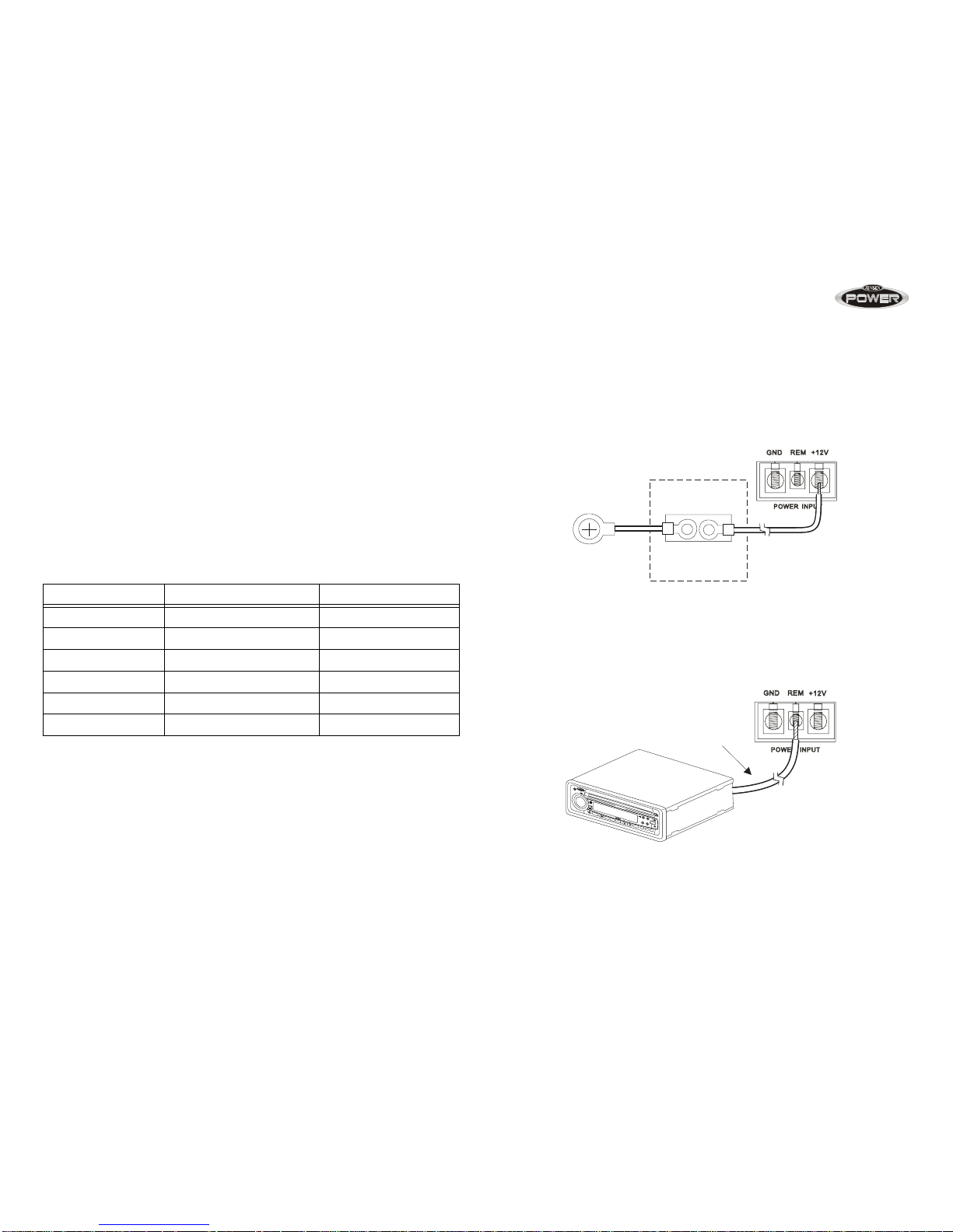
Power Terminal (+12V/B+)
Connect the main power wire to the battery, within 18 inches from the positive
(+) battery post, using an adequate size fuse or circuit breaker capable of
handling the current of the selected power wire. A fuse or circuit breaker must
be installed to prevent a possible electrical fire should the main power wire
short to ground.
Remote Terminal (REM)
Connect the power antenna or amplifier turn-on lead from the receiver to the
amplifier remote terminal.
MODEL NUMBER MAX CURRENT DRAW MIN WIRE GAUGE
400 25A #8
760 40A #8
880 60A #6
900 60A #6
920 60A #6
1050 100A #4
Fuse or Circuit Breaker
Install as close to the
battery as possible.
Battery Terminal
Adaptor
Remote Turn-On (Power Antenna)
B
B
L
E
T
A
A
A
D
F
R
S
UB-W
LOC/DX
1
2
3
INT
4
5
6
BAND
SCAN
EQ
MUTE
MODE
RPT
SHF
CD2620
DN
UP
i
i
X
-BASS
CHANGER
40WA
TTSx4
JPTH
CD-R/R
W
AUXIN
EQ
i
4
AUX
CDRECEIVER
E
L
R
E
S
S
B
VOL

POWER Amplifiers
5
Ground Terminal (GND)
Make the ground lead as short as possible, leaving enough length to complete
the installation and to allow for any service that may be need ed at a la ter date.
To ensure a good ground, scrape away any paint or undercoating to expose
bare metal. Use a «ring» terminal of the proper gauge and an «outside star
washer» (between the chassis and ring terminal) when making your ground
connection. Although you’ve scraped away the paint to expose bare metal, the
outside star washer will help to «bite into» the chassis for a tight, secure
ground.
Replacement Fuse Requirements (FUSE)
Model Quantity Amps Type
400 1 25 ATO
760 2 20 ATO
880 2 30 ATO
900 2 30 ATO
920 2 30 ATO
1050 4 25 ATO
Drill hole in chassis sheet metal.

POWER Amplifiers
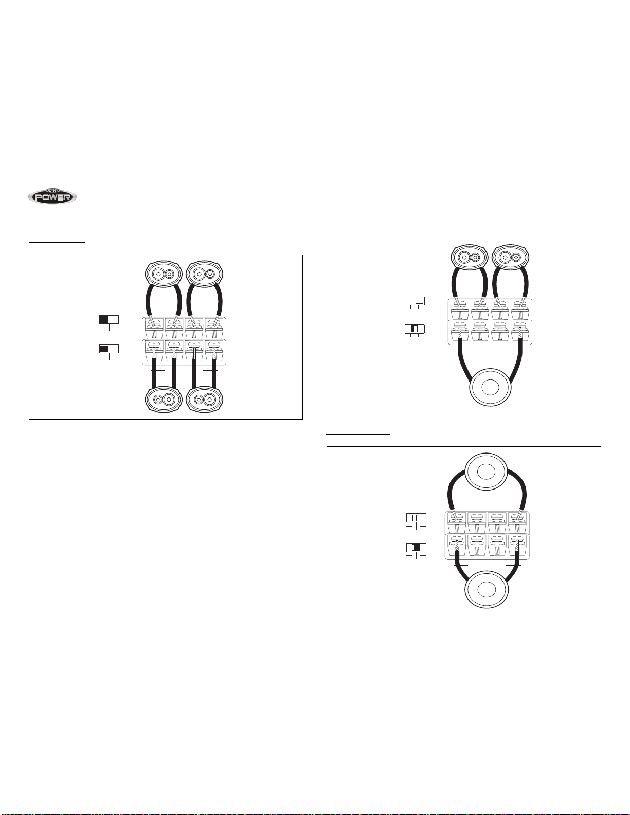
6
Speaker Wiring
The Speaker Wiring diagrams illustrate options for connecting one or two
speakers. Observe the proper speaker polarity.
NOTE: Power amplifiers can drive speakers with a nominal impedance
range of 2~ 4-ohms. For maximum power, configure your speakers for a
nominal 2-ohm load.
NOTE: Do not overlook the use of the proper gauge speaker wire. The
Power series of amplifiers require a minimum of 12-gauge wire.
Power 900/1050
Two Subwoofer One Subwoofer
Power 400/880
Two Speakers One Subwoofer
Tri-Mode
4 ohm 4 ohm
– – + +
SPEAKER OUTPUT
4 ohm nominal
– – + +
SPEAKER OUTPUT
SPEAKER OUTPUT
+ LEFT — + RIGHT —
BRIDGED
4 ohm nominal
MONO STEREO
MODE X-OVER
FULL
LPF
HPF
4 ohm nominal
+ LEFT — + RIGHT
BRIDGED
SPEAKER OUTPUT
MONO STEREO
MODE X-OVER
FULL
LPF
HPF
SPEAKER OUTPUT
+ LEFT — + RIGHT —
BRIDGED
4 ohm nominal
C
L
L
C
Inductor
Capacitor
X-OVER
FULL
LPF
HPF
POWER Amplifiers
7
Power 760/920
Four Speakers
Two Speakers and Bridged Subwoofer
Two Subwoofers
4 ohm nominal
2 ohm minimum
4 ohm nominal
2 ohm minimum
+ CH1 — + CH2 + CH3 — + CH4 —
+ BRIDGED —
X-OVER
FULL
LPF
HPF
FULL
LPF
HPF
4 ohm nominal
2 ohm minimum
4 ohm nominal
+ CH1 — + CH2 + CH3 — + CH4 —
+ BRIDGED —
X-OVER
FULL
LPF
HPF
FULL
LPF
HPF
4 ohm nominal
4 ohm nominal
+ CH1 — + CH2 + CH3 — + CH4 —
+ BRIDGED —
X-OVER
FULL
LPF
HPF
FULL
LPF
HPF
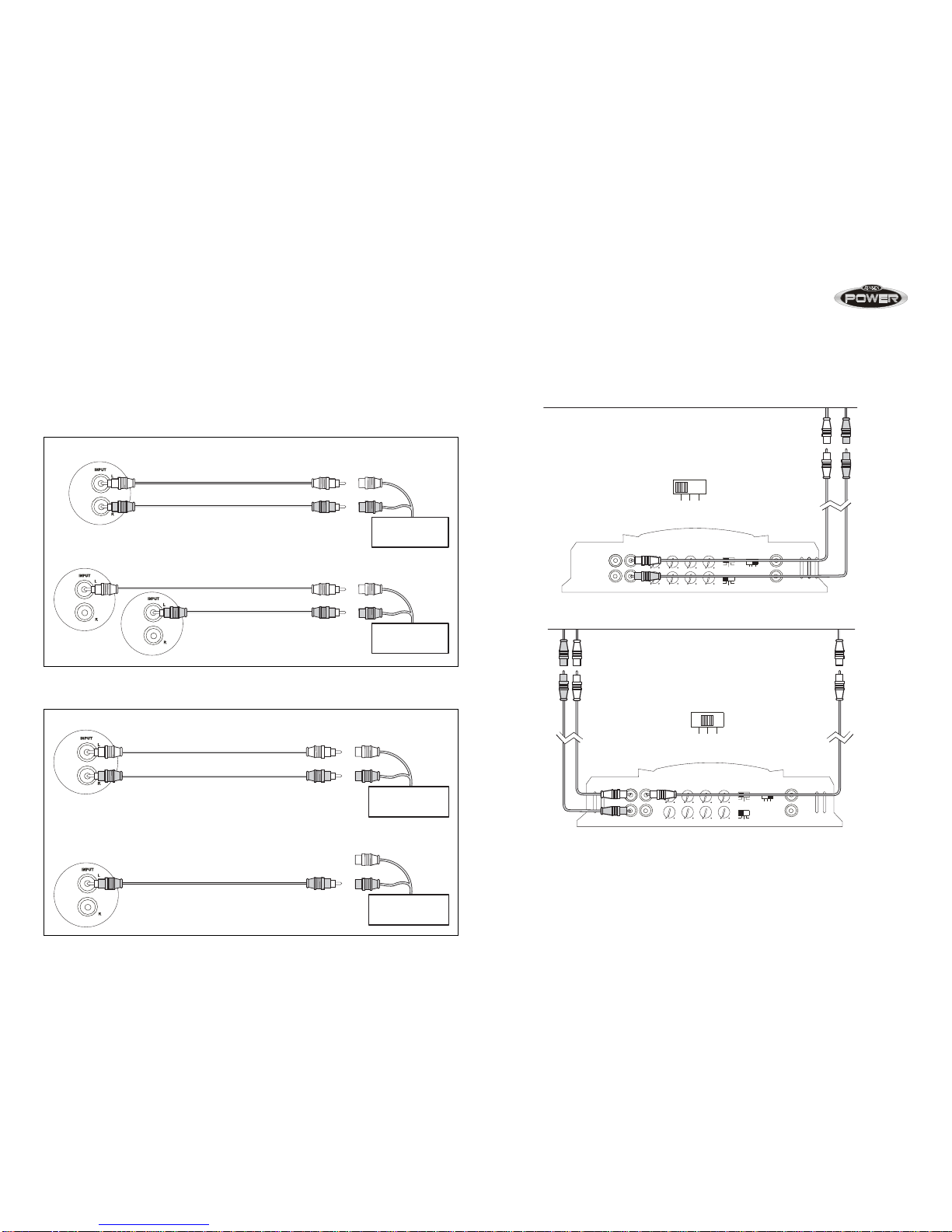
POWER Amplifiers
8
Input Wiring
Most trunk/hatchback installations will require a 15-20 foot RCA cable, while
pickup trucks and under-seat mounting will require a 6-12 foot RCA cable.
Connect an RCA cable from your receiver to the RCA input on your amplifier.
Power 400/880
Power 900/1050
Power 760/920
The Power 760 and 920 can be configured for three different input modes: 2
channel, 3 channel or 4 channel.
RCA Cable
CAR STEREO /
SOURCE UNIT
RCA Cable
CAR STEREO /
SOURCE UNIT
Input Wiring — Mono Mode
Input Wiring — Stereo Mode
RCA Cable
CAR STEREO /
SOURCE UNIT
RCA Cable
CAR STEREO /
SOURCE UNIT
Input Wiring — Mono Mode
Input Wiring — Mono Mode
min max 0dB 12dB40Hz 300Hz 40Hz 300Hz
min max 0dB 12dB40Hz 300Hz 40Hz 300Hz
LEVEL BASS EQ HPF LPF
X-OVER
FULL
LPF
HPF
FULL
LPF
HPF
234
MODE LINEOUT
2 Channel
CH3
CH4
CH1
CH2
LINEINPUT
234
MODE
min max 0dB 12dB40Hz 300Hz 40Hz 300Hz
min max 0dB 12dB40Hz 300Hz 40Hz 300Hz
LEVEL BASS EQ HPF LPF
X-OVER
FULL
LPF
HPF
FULL
LPF
HPF
234
MODE LINEOUT
CH3
CH4
CH1
CH2
LINEINPUT
3 Channel
234
MODE

POWER Amplifiers
9
NOTE: The use of good quality RCA cables is just as important as power
and speaker wire. Choose a high quality low capacitance cable for the
best results.
Connecting Additional Amplifiers
Pass-Thru RCA connectors are provided to connect additional amplifiers
without the need to purchase «Y» adapters.
min max 0dB 12dB40Hz 300Hz 40Hz 300Hz
min max 0dB 12dB40Hz 300Hz 40Hz 300Hz
LEVEL BASS EQ HPF LPF
X-OVER
FULL
LPF
HPF
FULL
LPF
HPF
234
MODE LINEOUT
CH3
CH4
CH1
CH2
LINEINPUT
4 Channel
234
MODE

POWER Amplifiers
10
Indicators and Controls
Power Indicator (POWER)
The power indicator provides a visual indication that the amplifier is turned on.
Input Level Control (LEVEL)
The input LEVEL control matches the output of your radio to the input of the
amplifier. After the inst allation is complete, make sure the input level control on
the amplifier is turned down all the way (counter-clockwise or all the way to the
left). Play a tape or CD (make sure bass and treble settings or Bass EQ are
flat) and turn the volume up slowly until you just start to hear distortion. Back
the volume down just a bit. On the amplifier, slowly turn up the input level
control (clockwise or to the right) until you just start to hear distortion, then
back it down a bit. Now your radio and amplifier levels are matched.
BASS EQ
The Bass EQ is continuously adjustable from 0 to +12dB @ 45Hz. Adjusting
the Bass Boost level allows different subwoofer/enclosure combinations to be
equalized. Use this control to increase the level of low bass available from your
subwoofer/enclosure combination. Ported and Band Pass enclosures should
be limited to about +6dB to +9dB of boost. Sealed enclosures should be able
to accept the full +12dB of boost, if necessary. The fu ll +12dB of boost should
be reserved for special applications since improper use of the Bass Boost
could damage your subwoofers at high volumes.
Low Pass Filter (LPF)
The Low Pass Filter controls adjust the crossover point. Typical crossover is
between 60Hz and 80Hz for ported and sealed enclosures. Bandpass boxes
will typically use a higher crossover setting between 125Hz and 150Hz. Since
musical tastes vary, you should play music that you would normally listen to in
your vehicle, with the above settings as a starting point. If necessary, set the
crossover by ear.
High Pass Filter (HPF)
The high pass filter will limit the low frequencies being transmitted to your
speakers. This can be useful in number of situations. For example, if you
selected the high pass filter and set the crossover to 40Hz, then you would
have an infra-sonic (sub-sonic) filter at 40Hz, which would be useful with
certain enclosure/subwoofer combinations that were tuned between 45Hz an d
50Hz. Other uses might include limiting the low frequencies to smaller
speakers (6 1/2″, 6 X 9″, etc.) by adjusting the crossover to a higher setting
(80–100Hz).
Crossover (X-OVER)
The Jensen Power series of amplifiers have built-in low-pass and high-pass
crossover filters for bi-amplifying the system. Adjust the crossover to
accommodate your chosen installation method. Select LPF (low pass filter)
when the amplifier will be driving woofers or subwoofers. Choose FULL when
crossover mode is not active and the amplifier is in “full range” mode. Select
HPF (high pass filter) when the amplifier will be driving full-range or separate
speakers, and you want to limit the “bass” being transferred to these speakers.
Mode Switch
Power 400 and 880
The 400 and 880 come equiped with a MONO/STEREO MODE switch. Use
STEREO mode when you have a 2-channel input from the source unit. Use
MONO mode when you have a single input from the source unit. See “Input
Wiring” on page 8.
Power 760 and 920
The 760 and 920 come equiped with a 2/3/4 MODE switch and can be
configured for three different input modes: 2 channel, 3 channel or 4 channel.
POWER Amplifiers
11
Testing
Before finishing the installation, perform the following tests to make sure the
wiring is correct and everything is operating properly.
Reconnect Battery
When wiring is complete, reconnect the battery negative terminal.
Test Power Wiring
Turn on the receiver, but do not turn up the volume. The amplifier powe r light
should come on. If not, check the REM and +12V (B+) wires. Turn up the
receiver volume slightly. All speakers should operate. If not, check wiring
connections at amplifier and speakers.
Test Speaker Connections
These tests make sure the speakers are connected proper ly. If speakers don’t
play at all, one (or both) speaker wires may be disconnected.
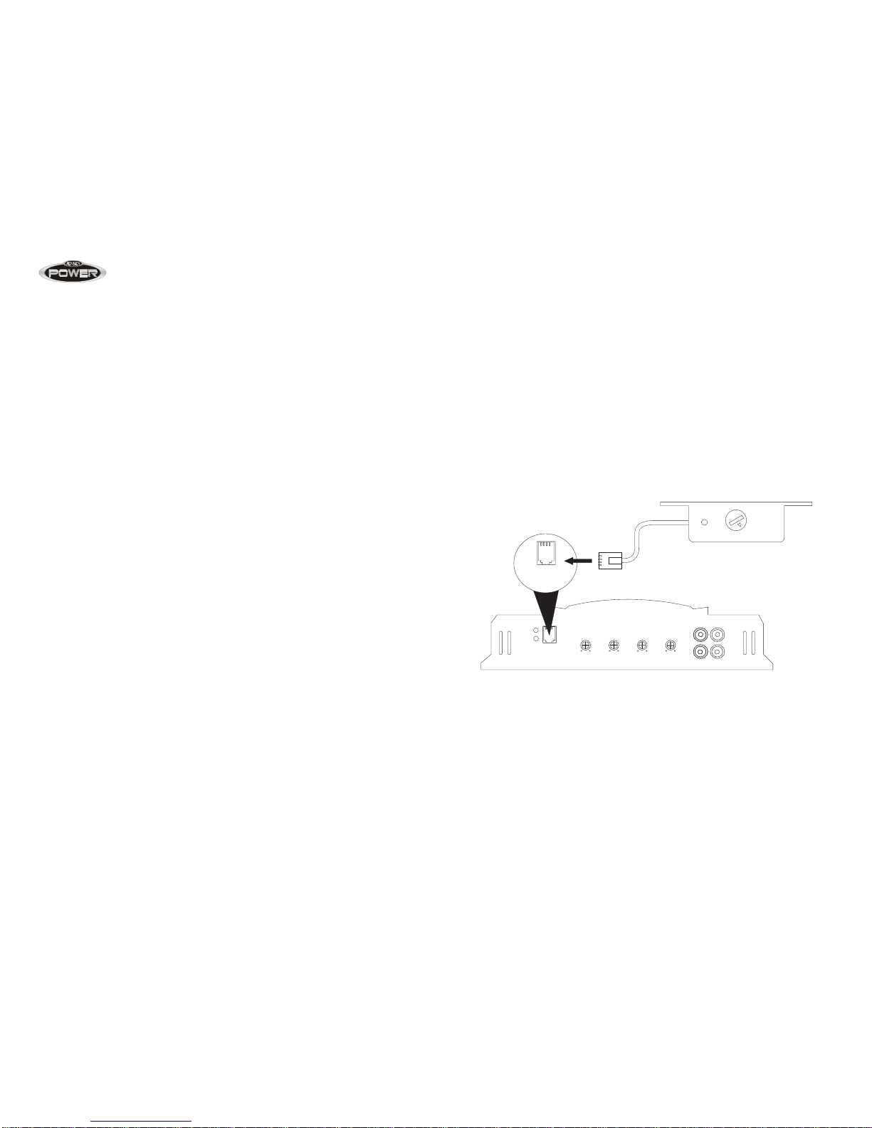
Remote Input Level Control
The Power 900 and 1050 come equipped with a Remote Input Level Control.
The Remote Input Level Control allows the input level to be adjusted from an
alternate location. It can be mounted under-dash or in-dash. When the
amplifier is used to drive subwoofers and the low pass crossover is activated,
the Remote Input Level Control can be used as a “remote bass level control”.
This enables you to control the bass level independent from the rest of the
system. This is convenient for system tuning and/or when playing many
different types of music.
The Remote Input Level Control uses a 6-pin modular cable for connectivity.
Simply plug the 6-pin modular cable into the amplifier and then into the
Remote Input Level Control to activate the circuit.
Power
Min Max
L
R
L
R
OUTPUT INPUT
0dB 12dB 10Hz 40Hz 40Hz 300Hz 4V 0.4V
BASS
BOOST
SUB
SONIC
LOW
PASS
LEVEL
REMOTE
CONTROL
POWER
PROTECT
REMOTE
CONTROL
POWER Amplifiers
12
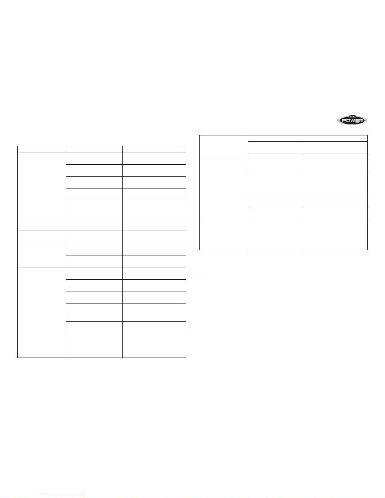
Troubleshooting
NOTE: If the protection light is activated with no speakers connected to
the amplifier, and all the power conn ections are correct, this would
indicate an internal problem with the amplifier.
Problem Possible Cause Corrective Action
Amplifier does not
turn on
No power to +12V
terminal
Check fuse(s)
No power to REM
terminal
Check head unit fuse(s) and
wiring
Blown main fuse at
battery
Replace fuse and identify
cause of failure
Blown fuse at amplifier Replace fuse and identify
cause of failure
Faulty ground Re-ground main power
ground to bare metal
chassis
Volume control too
sensitive
Input level control
adjusted too high
Re-adjust the input level
(refer to page 
Distorted sound Input level control
adjusted too high
Re-adjust the input level
(refer to page
Blows fuse(s) at amp Power wires connected
backwards
Reconnect power wires
properly
Internal problem with
amp
Take unit for service
Engine noise /
Alternator whine
Ground loop(s) Use good quality shielded
RCA cables
Faulty ground at amp Re-ground amp to clean
bare metal chassis
Faulty ground at head
unit
Re-ground head unit to
clean bare metal chassis
Inductive coupling Re-route RCA and/or
speaker wires away from
factory harnesses
Input level on amp set
too high
Re-adjust input level (refer
to page
Thermal protection
activated
Amplifier driving 2 ohm
load for long durations
If the amplifier “thermals”
frequently while driving
subwoofers, install fan to
keep amp cool.
Short circuit
protection activated
Blown speakers Check all speakers
Speaker wire(s) shorting
to ground
Check for faulty wiring
Defective crossover Faulty passive crossover
Low impedance
protection activated
Amp connected to
improper load
Check speaker connections
Amp will not drive a 1
ohm mono load, 2 ohm
minimum in mono
configuration
Verify that speakers are
connected properly
Speakers defective/
blown
Check speakers
Faulty passive
crossovers
Check crossovers
Poor bass response Speakers out of phase Check speaker polarity;
reverse the connection to
one speaker only if two
subwoofers are connected
to the amplifier.

POWER Amplifiers
13
CEA Power Output
RMS Power Output @ 1% THD+N, 14.4VDC
Power 400
Power Output: 60 watts RMS X 2 channels into 4-ohms @ < 1% THD+N
Signal to Noise Ratio: 100dBA below reference (Reference: 1 watt, 4-ohms)
Additional Power Output:
80 watts RMS X 2 channels into 2-ohms @ < 1% THD+N
160 watts RMS X 1 channels (Bridged Mono) into 4-ohms @ < 1% THD+N
Frequency Response: 10Hz to 60 kHz, -3dB (Reference: 1 watt)
Dimensions: L9.5″ x H2.5″ x W9.0″
Power 760
Power Output: 60 watts RMS X 4 channels into 4-ohms @ < 1% THD+N
Signal to Noise Ratio: 100dBA below reference (Reference: 1 watt, 4-ohms)
Additional Power Output:
80 watts RMS X 4 channels into 2-ohms @ < 1% THD+N
155 watts RMS X 2 channels (Bridged Stereo) into 4-ohms @ < 1% THD+N
Frequency Response: 10Hz to 60 kHz, -3dB (Reference: 1 watt)
Dimensions: L12.5″ x H2.5″ x W9.0″
Power 880
Power Output: 125 watts RMS X 2 channels into 4-ohms @ < 1% THD+N
Signal to Noise Ratio: 100dBA below reference (Reference: 1 watt, 4-ohms)
Additional Power Output:
200 watts RMS X 2 channels into 2-ohms @ < 1% THD+N
410 watts RMS X 1 channels (Bridged Mono) into 4-ohms @ < 1% THD+N
Frequency Response: 10Hz to 60kHz, -3dB (Reference: 1 watt)
Dimensions: L14.0″ x H2.5″ x W9.0″
Power 900
Power Output: 230 watts RMS X 1 channels into 4-ohms @ < 1% THD+N
Signal to Noise Ratio: 100dBA below reference (Reference: 1 watt, 4-ohms)
Additional Power Output:
340 watts RMS X 1 channels into 2-ohms @ < 1% THD+N
Frequency Response: 10Hz to 240Hz, -3dB (Reference: 1 watt)
Dimensions: L15.75″ x H2.5″ x W9.0″
Power 920
Power Output: 90 watts RMS X 4 channels into 4-ohms @ < 1% THD+N
Signal to Noise Ratio: 100dBA below reference (Reference: 1 watt, 4-ohms)
Additional Power Output:
120 watts RMS X 4 channels into 2-ohms @ < 1% THD+N
190 watts RMS X 2 channels (Bridged Stereo) into 4-ohms @ < 1% THD+N
Frequency Response: 10Hz to 60 kHz, -3dB (Reference: 1 watt)
Dimensions: L15.75″ x H2.5″ x W9.0″
Power 1050
Power Output: 290 watts RMS X 1 channels into 4-ohms @ < 1% THD+N
Signal to Noise Ratio: 100dBA below reference (Reference: 1 watt, 4-ohms)
Additional Power Output:
430 watts RMS X 1 channel into 2-ohms @ < 1% THD+N
Frequency Response: 10Hz to 150Hz, -3dB (Reference: 1 watt)
Dimensions: L17.25″ x H2.5″ x W9.0″
Loading…