
To reduce the impacts on global warming, the packaging materials of this product
are recyclable and reusable. GIGABYTE works with you to protect the environment.
Z690 GAMING X
Z690 GAMING X DDR4
User’s Manual
Rev. 1002
12ME-Z69GX4-1002R
For more product details, please visit GIGABYTE’s website.
Z690 GAMING X Z690 GAMING X DDR4
Copyright
© 2021 GIGA-BYTE TECHNOLOGY CO., LTD. All rights reserved.
The trademarks mentioned in this manual are legally registered to their respective owners.
Disclaimer
Information in this manual is protected by copyright laws and is the property of GIGABYTE.
Changes to the specications and features in this manual may be made by GIGABYTE without
prior notice. No part of this manual may be reproduced, copied, translated, transmitted, or
published in any form or by any means without GIGABYTE’s prior written permission.
In order to assist in the use of this product, carefully read the User’s Manual.
For product-related information, check on our website at: https://www.gigabyte.com
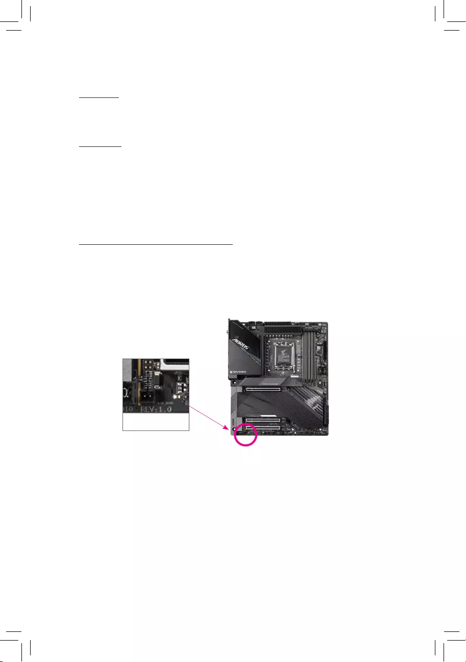
Identifying Your Motherboard Revision
The revision number on your motherboard looks like this: «REV: X.X.» For example,
«REV: 1.0″ means the revision of the motherboard is 1.0. Check your motherboard revision
before updating motherboard BIOS, drivers, or when looking for technical information.
Example:

— 3 —
Table of Contents
Chapter 1 Product Introduction ……………………………………………………………………………4
1-1 Motherboard Layout …………………………………………………………………………….. 4
1-2 Box Contents ………………………………………………………………………………………. 6
Chapter 2 Hardware Installation ………………………………………………………………………….7
2-1 Installation Precautions ………………………………………………………………………… 7
2-2 Product Specications ………………………………………………………………………….. 8
2-3 Installing the CPU and CPU Cooler ……………………………………………………… 12
2-4 Installing the Memory …………………………………………………………………………. 15
2-5 Installing an Expansion Card ………………………………………………………………. 16
2-6 Back Panel Connectors ………………………………………………………………………. 17
2-7 Internal Connectors ……………………………………………………………………………. 19
Chapter 3 BIOS Setup ……………………………………………………………………………………..33
Chapter 4 Installing the Operating System and Drivers ………………………………………… 35
4-1 Operating System Installation ……………………………………………………………… 35
4-2 Drivers Installation ……………………………………………………………………………… 36
Chapter 5 Appendix …………………………………………………………………………………………37
5-1 Conguring a RAID Set ………………………………………………………………………. 37
Regulatory Notices ………………………………………………………………………………………. 38
Contact Us …………………………………………………………………………………………………. 40
— 4 —
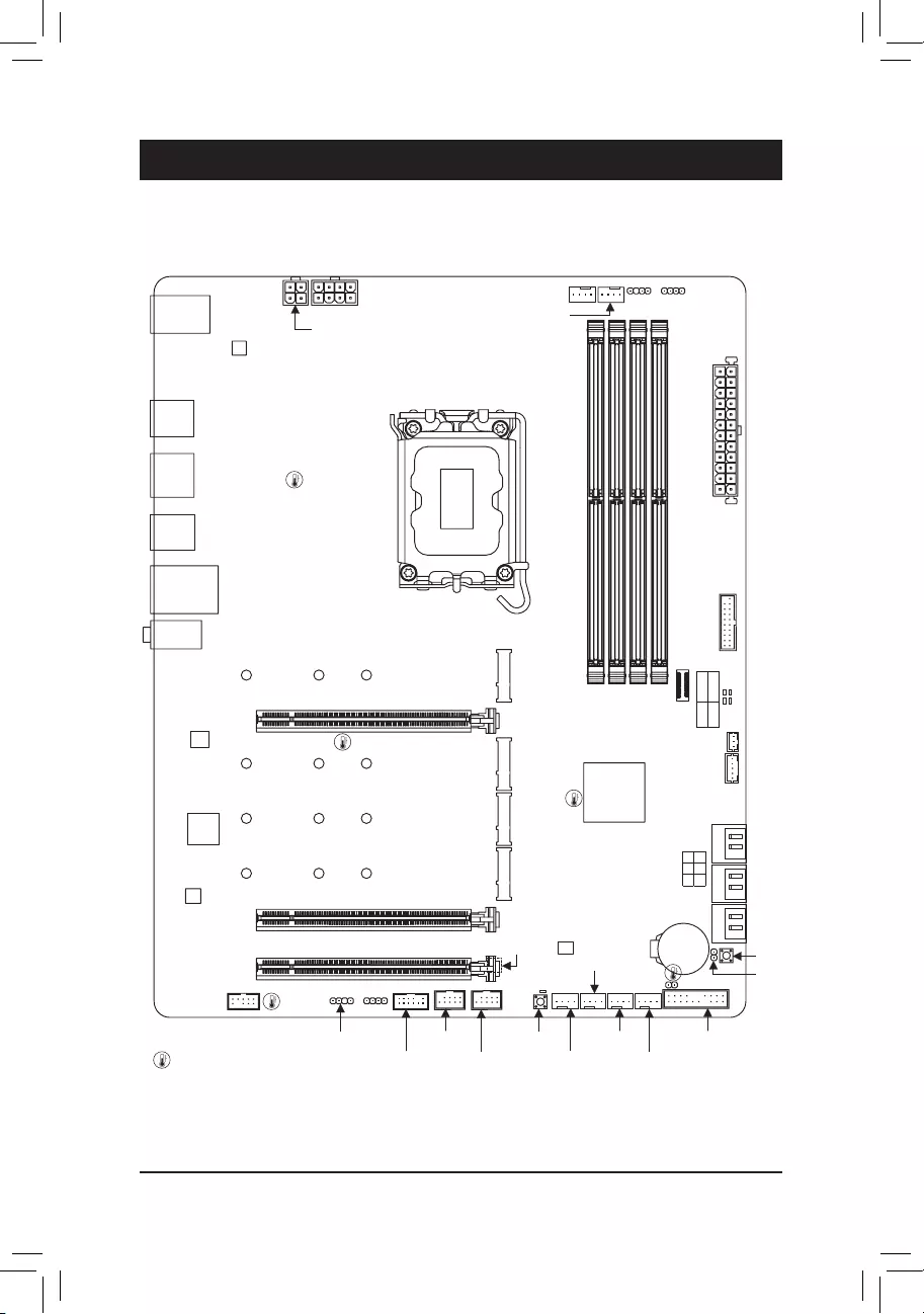
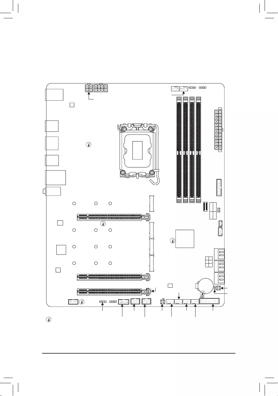
1-1 Motherboard Layout
Chapter 1 Product Introduction
Temperature sensor
DP_HDMI20
U32
U320G
U32_LAN
LGA1700
ATX
AUDIO
DDR5_A1
DDR5_A2
DDR5_B1
DDR5_B2
BAT
Intel® Z690
CLR_CMOS
M_BIOS
THB_C1
THB_C2
CODEC
PCIEX16
PCIEX4_1
PCIEX4_2
F_U32C
F_U32
USB20
6080110
M2A_CPU
SYS_FAN1
F_USB2D_LED1
F_AUDIO
F_USB1
LED_C1
SYS_FAN3
SPI_TPM
F_PANEL
CPU_FAN
CPU_OPT
SYS_FAN4_PUMP
iTE®
Super I/O
D_LED2 LED_C2
ATX_12V_2X4
ATX_12V_2X2
USB 2.0 Hub
SATA3 357
246 CPU DRAM
VGA BOOT
U32G2
Realtek®
2.5GbE LAN
RST_SW
RST
SYS_FAN2
QFLED
QFLASH_PLUS
6080110
M2P_SB
6080110
M2Q_SB
6080110
M2M_SB
Z690 GAMING X
USB 2.0 Hub
— 5 —
DP_HDMI20
U32
U320G
U32_LAN
LGA1700
ATX
AUDIO
DDR4_A1
DDR4_A2
DDR4_B1
DDR4_B2
BAT
Intel® Z690
CLR_CMOS
M_BIOS
THB_C1
THB_C2
CODEC
PCIEX16
PCIEX4_1
PCIEX4_2
F_U32C
F_U32
USB20
6080110
M2A_CPU
Z690 GAMING X DDR4
SYS_FAN1
F_USB2D_LED1
F_AUDIO
F_USB1
LED_C1
SYS_FAN3
SPI_TPM
F_PANEL
CPU_FAN
CPU_OPT
SYS_FAN4_PUMP
iTE®
Super I/O
D_LED2 LED_C2
ATX_12V_2X4
ATX_12V_2X2
USB 2.0 Hub
SATA3 357
246 CPU DRAM
VGA BOOT
U32G2
Realtek®
2.5GbE LAN
RST_SW
RST
SYS_FAN2
QFLED
QFLASH_PLUS
6080110
M2P_SB
6080110
M2Q_SB
6080110
M2M_SB
Temperature sensor
USB 2.0 Hub

— 6 —
1-2 Box Contents
5Z690 GAMING X or Z690 GAMING X DDR4 motherboard
5User’s Manual
5Two SATA cables
5M.2 screws
* The box contents above are for reference only and the actual items shall depend on the product package you obtain.
The box contents are subject to change without notice.

— 7 —
2-1 Installation Precautions
The motherboard contains numerous delicate electronic circuits and components which can become
damaged as a result of electrostatic discharge (ESD). Prior to installation, carefully read the user’s
manual and follow these procedures:
•Prior to installation, make sure the chassis is suitable for the motherboard.
•Prior to installation, do not remove or break motherboard S/N (Serial Number) sticker or
warranty sticker provided by your dealer. These stickers are required for warranty validation.
•Always remove the AC power by unplugging the power cord from the power outlet before
installing or removing the motherboard or other hardware components.
•When connecting hardware components to the internal connectors on the motherboard, make
sure they are connected tightly and securely.
•When handling the motherboard, avoid touching any metal leads or connectors.
•It is best to wear an electrostatic discharge (ESD) wrist strap when handling electronic
components such as a motherboard, CPU or memory. If you do not have an ESD wrist strap,
keep your hands dry and rst touch a metal object to eliminate static electricity.
•Prior to installing the motherboard, please have it on top of an antistatic pad or within an
electrostatic shielding container.
•Before connecting or unplugging the power supply cable from the motherboard, make sure
the power supply has been turned off.
•Before turning on the power, make sure the power supply voltage has been set according to
the local voltage standard.
•Before using the product, please verify that all cables and power connectors of your hardware
components are connected.
•To prevent damage to the motherboard, do not allow screws to come in contact with the
motherboard circuit or its components.
•Make sure there are no leftover screws or metal components placed on the motherboard or
within the computer casing.
•Do not place the computer system on an uneven surface.
•Do not place the computer system in a high-temperature or wet environment.
•Turning on the computer power during the installation process can lead to damage to system
components as well as physical harm to the user.
•If you are uncertain about any installation steps or have a problem related to the use of the
product, please consult a certied computer technician.
•If you use an adapter, extension power cable, or power strip, ensure to consult with its installation
and/or grounding instructions.
Chapter 2 Hardware Installation
— 8 —
2-2 ProductSpecications
CPU LGA1700 socket: Support for 12th Generation Intel® Core™ i9 processors/Intel®
Core™ i7 processors/Intel® Core™ i5 processors
(Go to GIGABYTE’s website for the latest CPU support list.)
L3 cache varies with CPU
Chipset Intel® Z690 Express Chipset
Memory Support for DDR5 4800/4000 MHz memory modulesj
Support for DDR4 3200/3000/2933/2666/2400/2133 MHz memory modulesk
4 x DDR DIMM sockets supporting up to 128 GB (32 GB single DIMM capacity)
of system memory
Dual channel memory architecture
Support for ECC Un-buffered DIMM 1Rx8/2Rx8 memory modules (operate in
non-ECC mode)
Support for non-ECC Un-buffered DIMM 1Rx8/2Rx8/1Rx16 memory modules
Support for Extreme Memory Prole (XMP) memory modules
(Go to GIGABYTE’s website for the latest supported memory speeds and memory
modules.)
Onboard
Graphics
Integrated Graphics Processor-Intel® HD Graphics support:
— 1 x HDMI port, supporting a maximum resolution of 4096×2160@60 Hz
* Support for HDMI 2.0 version and HDCP 2.3.
— 1 x DisplayPort, supporting a maximum resolution of 4096×2304@60 Hz
* Support for DisplayPort 1.2 version and HDCP 2.3
(Graphics specications may vary depending on CPU support.)
Audio Realtek® ALC1220-VB CODEC
* The back panel line out jack supports DSD audio.
High Denition Audio
2-channel analog output
Support for S/PDIF Out
— 7.1-channel digital signals
* Actual output of digital signals may vary depending on the playback content and
software used, and an external DAC is required.
LAN Realtek® 2.5GbE LAN chip (2.5 Gbps/1 Gbps/100 Mbps)
Expansion Slots 1 x PCI Express x16 slot, running at x16 (PCIEX16)
* For optimum performance, if only one PCI Express graphics card is to be installed,
be sure to install it in the PCIEX16 slot.
(The PCIEX16 slot conforms to PCI Express 5.0 standard.)
2 x PCI Express x16 slots, running at x4 (PCIEX4_1, PCIEX4_2)
(The PCIEX4 slots conform to PCI Express 3.0 standard.)
Multi-Graphics
Technology Support for AMD Quad-GPU CrossFire™ and 2-Way AMD CrossFire™ technologies
j Only for Z690 GAMING X.
k Only for Z690 GAMING X DDR4.
— 9 —
Storage Interface CPU:
— 1 x M.2 connector (Socket 3, M key, type 2260/2280/22110 PCIe 4.0 x4/x2
SSD support) (M2A_CPU)
Chipset:
— 2 x M.2 connector (Socket 3, M key, type 2260/2280/22110 PCIe 4.0 x4/x2
SSD support) (M2P_SB, M2Q_SB)
— 1 x M.2 connector (Socket 3, M key, type 2260/2280/22110 SATA and PCIe 4.0
x4/x2 SSD support) (M2M_SB)
— 6 x SATA 6Gb/s connectors
Support for RAID 0, RAID 1, RAID 5, and RAID 10
* Refer to «2-7 Internal Connectors,» for the installation notices for the M.2 and SATA
connectors.
Intel® Optane™ Memory Ready
* System acceleration with Intel® Optane™ Memory can only be enabled on the M.2
connectors supported by the Chipset.
USB Chipset:
— 1 x USB Type-C® port on the back panel, with USB 3.2 Gen 2×2 support
— 1 x USB Type-C® port with USB 3.2 Gen 2 support, available through the
internal USB header
— 2 x USB 3.2 Gen 2 Type-A ports (red) on the back panel
— 5 x USB 3.2 Gen 1 ports (3 ports on the back panel, 2 ports available
through the internal USB header)
Chipset+2 USB 2.0 Hubs:
— 8 x USB 2.0/1.1 ports (4 ports on the back panel, 4 ports available through
the internal USB headers)
Internal
Connectors
1 x 24-pin ATX main power connector
1 x 8-pin ATX 12V power connector
1 x 4-pin ATX 12V power connector
1 x CPU fan header
1 x water cooling CPU fan header
3 x system fan headers
1 x system fan/water cooling pump header
2 x addressable LED strip headers
2 x RGB LED strip headers
4 x M.2 Socket 3 connectors
6 x SATA 6Gb/s connectors
1 x front panel header
1 x front panel audio header
1 x USB Type-C® header, with USB 3.2 Gen 2 support
1 x USB 3.2 Gen 1 header
2 x USB 2.0/1.1 headers
2 x Thunderbolt™ add-in card connectors
1 x Trusted Platform Module header (For the GC-TPM2.0 SPI/GC-TPM2.0 SPI
2.0 module only)
1 x Q-Flash Plus button
1 x reset button
1 x reset jumper
1 x Clear CMOS jumper
— 10 —
Back Panel
Connectors
1 x USB Type-C® port, with USB 3.2 Gen 2×2 support
2 x USB 3.2 Gen 2 Type-A ports (red)
3 x USB 3.2 Gen 1 ports
4 x USB 2.0/1.1 ports
1 x HDMI port
1 x DisplayPort
1 x RJ-45 port
1 x optical S/PDIF Out connector
2 x audio jacks
I/O Controller iTE® I/O Controller Chip
Hardware
Monitor
Voltage detection
Temperature detection
Fan speed detection
Water cooling ow rate detection
Fan fail warning
Fan speed control
* Whether the fan (pump) speed control function is supported will depend on the fan
(pump) you install.
BIOS 1 x 256 Mbit ash
Use of licensed AMI UEFI BIOS
PnP 1.0a, DMI 2.7, WfM 2.0, SM BIOS 2.7, ACPI 5.0
Unique Features Support for APP Center
* Available applications in APP Center may vary by motherboard model. Supported
functions of each application may also vary depending on motherboard specications.
— @BIOS
— EasyTune
— Fast Boot
— Game Boost
— ON/OFF Charge
— RGB Fusion
— Smart Backup
— System Information Viewer
Support for Q-Flash Plus
Support for Q-Flash
Support for Xpress Install
— 11 —
Please visit GIGABYTE’s website for support lists of CPU, memory modules,
SSDs, and M.2 devices.
Please visit the Support\Utility List page on GIGABYTE’s website to download the latest
version of apps.
Bundled
Software
Norton® Internet Security (OEM version)
Realtek® Gaming LAN Bandwidth Control Utility
Operating
System Support for Windows 10 64-bit
Form Factor ATX Form Factor; 30.5cm x 24.4cm
* GIGABYTE reserves the right to make any changes to the product specications and product-related information without
prior notice.
Z690 GAMING X Z690 GAMING X DDR4
— 12 —
2-3 Installing the CPU and CPU Cooler
Read the following guidelines before you begin to install the CPU:
•Make sure that the motherboard supports the CPU.
(Go to GIGABYTE’s website for the latest CPU support list.)
•Always turn off the computer and unplug the power cord from the power outlet before installing the
CPU to prevent hardware damage.
•Locate the pin one of the CPU. The CPU cannot be inserted if oriented incorrectly. (Or you may
locate the notches on both sides of the CPU and alignment keys on the CPU socket.)
•Apply an even and thin layer of thermal grease on the surface of the CPU.
•Do not turn on the computer if the CPU cooler is not installed, otherwise overheating and damage
of the CPU may occur.
•Set the CPU host frequency in accordance with the CPU specications. It is not recommended
that the system bus frequency be set beyond hardware specications since it does not meet the
standard requirements for the peripherals. If you wish to set the frequency beyond the standard
specications, please do so according to your hardware specications including the CPU, graphics
card, memory, hard drive, etc.
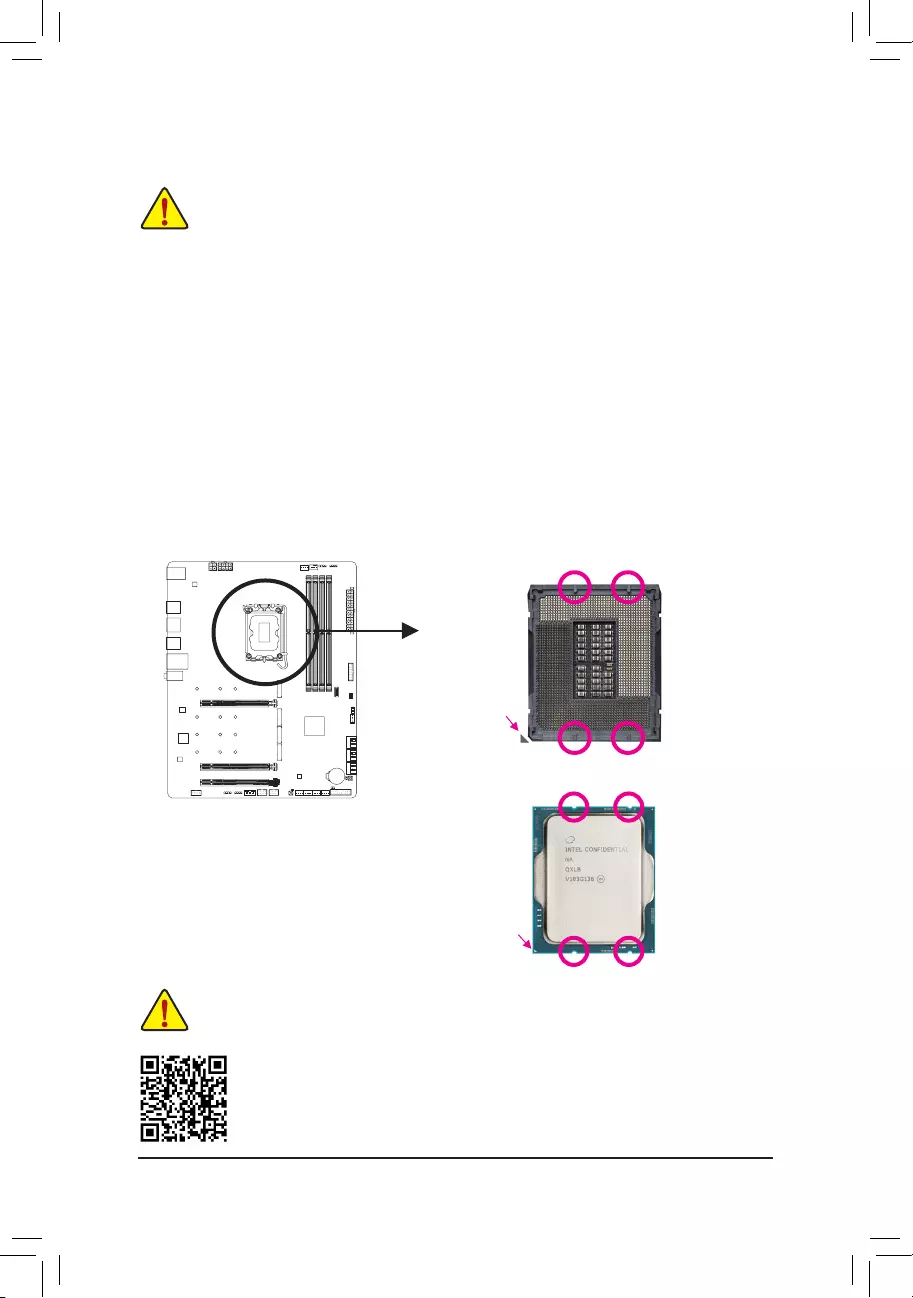
A. Note the CPU Orientation
Note the alignment keys on the motherboard CPU socket and the notches on the CPU.
Please visit GIGABYTE’s website for details on hardware installation.
Do not remove the CPU socket cover before inserting the CPU. It may pop off from the load
plate automatically after you insert the CPU and close the load plate.
Notch
Notch
LGA1700 CPU
Triangle Pin One Marking
on the CPU
Alignment Key
LGA1700 CPU Socket
Triangle Pin One Marking
of the CPU Socket
Alignment Key
— 13 —
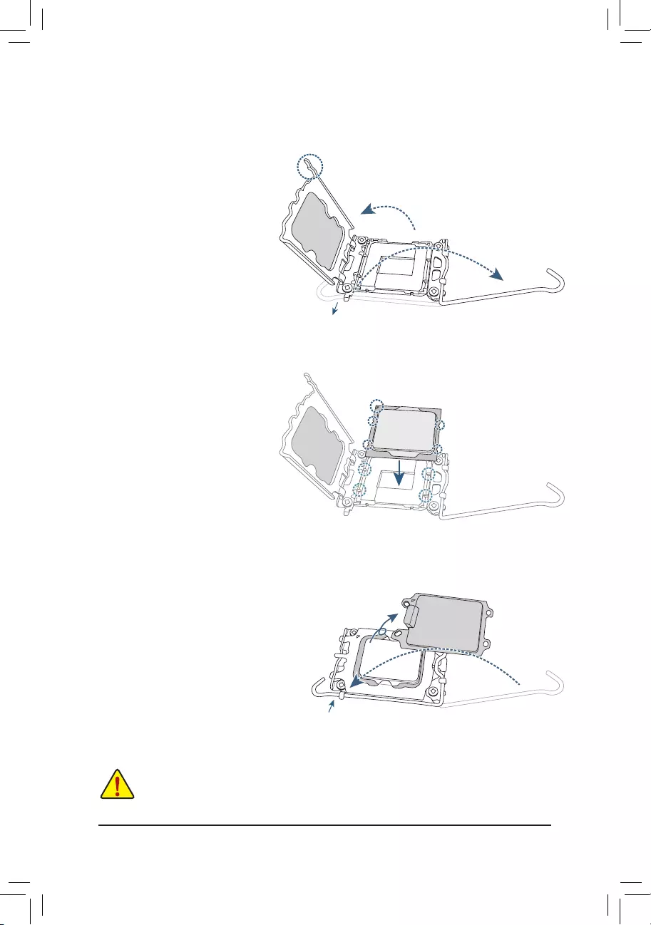
Do not force to engage the CPU socket locking lever when the CPU is not installed correctly
as this would damage the CPU and CPU socket.
B. Installing the CPU
Follow the steps below to correctly install the CPU into the motherboard CPU socket.
w
u
v
jGently press the CPU socket lever handle
down and away from the socket.
kCompletely lift up the CPU socket lock—
ing lever.
lUse the finger tab on the side of the
metal load plate to lift open the metal
load plate with the plastic protective cover
attached to it.
Hold the CPU with your ngers by the edges.
Align the CPU pin one marking (triangle) with
the pin one corner of the CPU socket (or you
may align the CPU notches with the socket
alignment keys) and gently insert the CPU
into position.
Make sure the CPU is properly installed and
then close the load plate. The plastic protec-
tive cover will pop off, just remove it. Secure
the lever under its retention tab to complete
the installation of the CPU.
* Always replace the plastic protective cover
when the CPU is not installed to protect the
CPU socket.
j
k
l
Finger Tab
Pin One
j
k
l
— 14 —
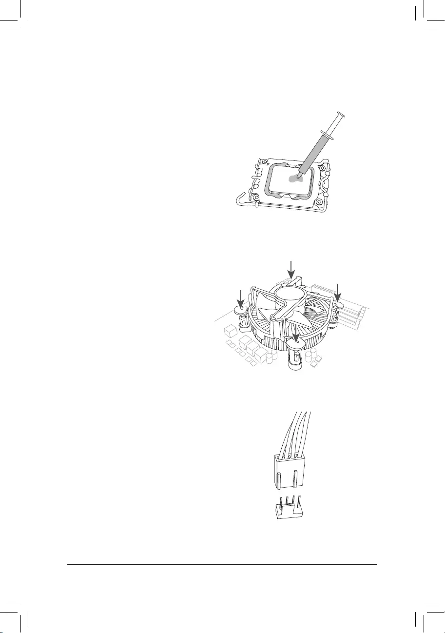
C. Installing the CPU Cooler
Be sure to install the CPU cooler after installing the CPU. (Actual installation process may differ depending the
CPU cooler to be used. Refer to the user’s manual for your CPU cooler.)
u
v
Apply an even and thin layer of thermal
grease on the surface of the installed CPU.
Place the cooler atop the CPU, aligning the
four push pins through the pin holes on the
motherboard. Push down on the push pins
diagonally.
j
j
kk
w
Finally, attach the power connector of
the CPU cooler to the CPU fan header
(CPU_FAN) on the motherboard.
CPU_FAN
— 15 —
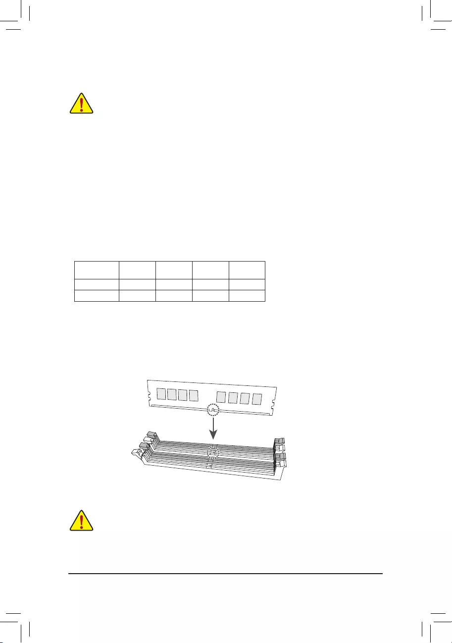
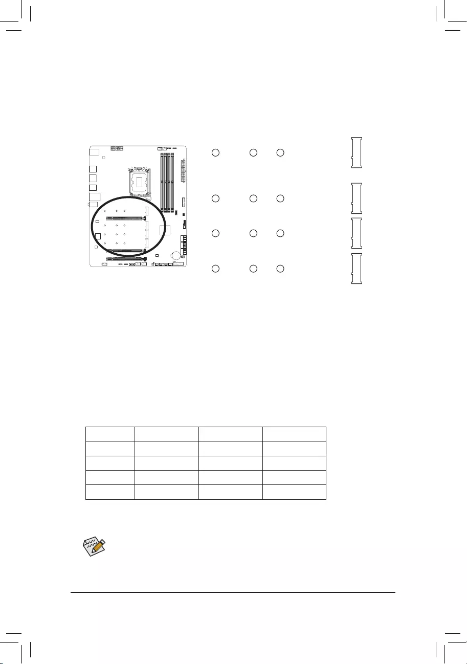
2-4 Installing the Memory
Read the following guidelines before you begin to install the memory:
•Make sure that the motherboard supports the memory. It is recommended that memory of the same
capacity, brand, speed, and chips be used. (Go to GIGABYTE’s website for the latest supported
memory speeds and memory modules.)
•Always turn off the computer and unplug the power cord from the power outlet before installing the
memory to prevent hardware damage.
•Memory modules have a foolproof design. A memory module can be installed in only one direction.
If you are unable to insert the memory, switch the direction.
DualChannelMemoryConguration
This motherboard provides four memory sockets and supports Dual Channel Technology. After the memory
is installed, the BIOS will automatically detect the specications and capacity of the memory. Enabling Dual
Channel memory mode will double the original memory bandwidth.
The four memory sockets are divided into two channels and each channel has two memory sockets as following:
Channel A: DDR5_A1j/DDR4_A1k, DDR5_A2j/DDR4_A2k
Channel B: DDR5_B1j/DDR4_B1k, DDR5_B2j/DDR4_B2k
* Recommanded Dual Channel Memory Conguration:
DDR5_ A1j
DDR4_ A1k
DDR5_A2j
DDR4_A2k
DDR5_B1j
DDR4_B1k
DDR5_B2j
DDR4_B2k
2 Modules — — DS/SS — — DS/SS
4 Modules DS/SS DS/SS DS/SS DS/SS
(SS=Single-Sided, DS=Double-Sided, «- -«=No Memory)
Due to CPU limitations, read the following guidelines before installing the memory in Dual Channel mode.
1. Dual Channel mode cannot be enabled if only one memory module is installed.
2. When enabling Dual Channel mode with two or four memory modules, it is recommended that memory of
the same capacity, brand, speed, and chips be used.
When installing a single memory module, we recommend that you install it in the DDR5_A2j/
DDR4_A2k socket.
DDR5_A1j/DDR4_A1k
DDR5_A2j/DDR4_A2k
DDR5_B1j/DDR4_B1k
DDR5_B2j/DDR4_B2k
j Only for Z690 GAMING X.
k Only for Z690 GAMING X DDR4.
— 16 —
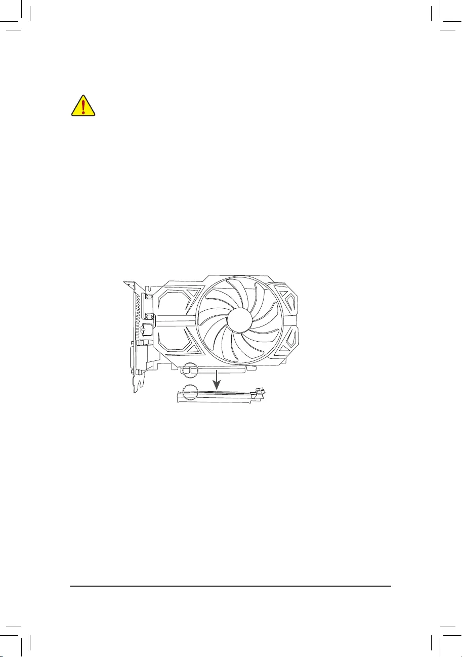
2-5 Installing an Expansion Card
Read the following guidelines before you begin to install an expansion card:
•Make sure the motherboard supports the expansion card. Carefully read the manual that came
with your expansion card.
•Always turn off the computer and unplug the power cord from the power outlet before installing an
expansion card to prevent hardware damage.
Follow the steps below to correctly install your expansion card in the expansion slot.
1. Locate an expansion slot that supports your card. Remove the metal slot cover from the chassis back panel.
2. Align the card with the slot, and press down on the card until it is fully seated in the slot.
3. Make sure the metal contacts on the card are completely inserted into the slot.
4. Secure the card’s metal bracket to the chassis back panel with a screw.
5. After installing all expansion cards, replace the chassis cover(s).
6. Turn on your computer. If necessary, go to BIOS Setup to make any required BIOS changes for your
expansion card(s).
7. Install the driver provided with the expansion card in your operating system.
PCIEX16 Slot
— 17 —
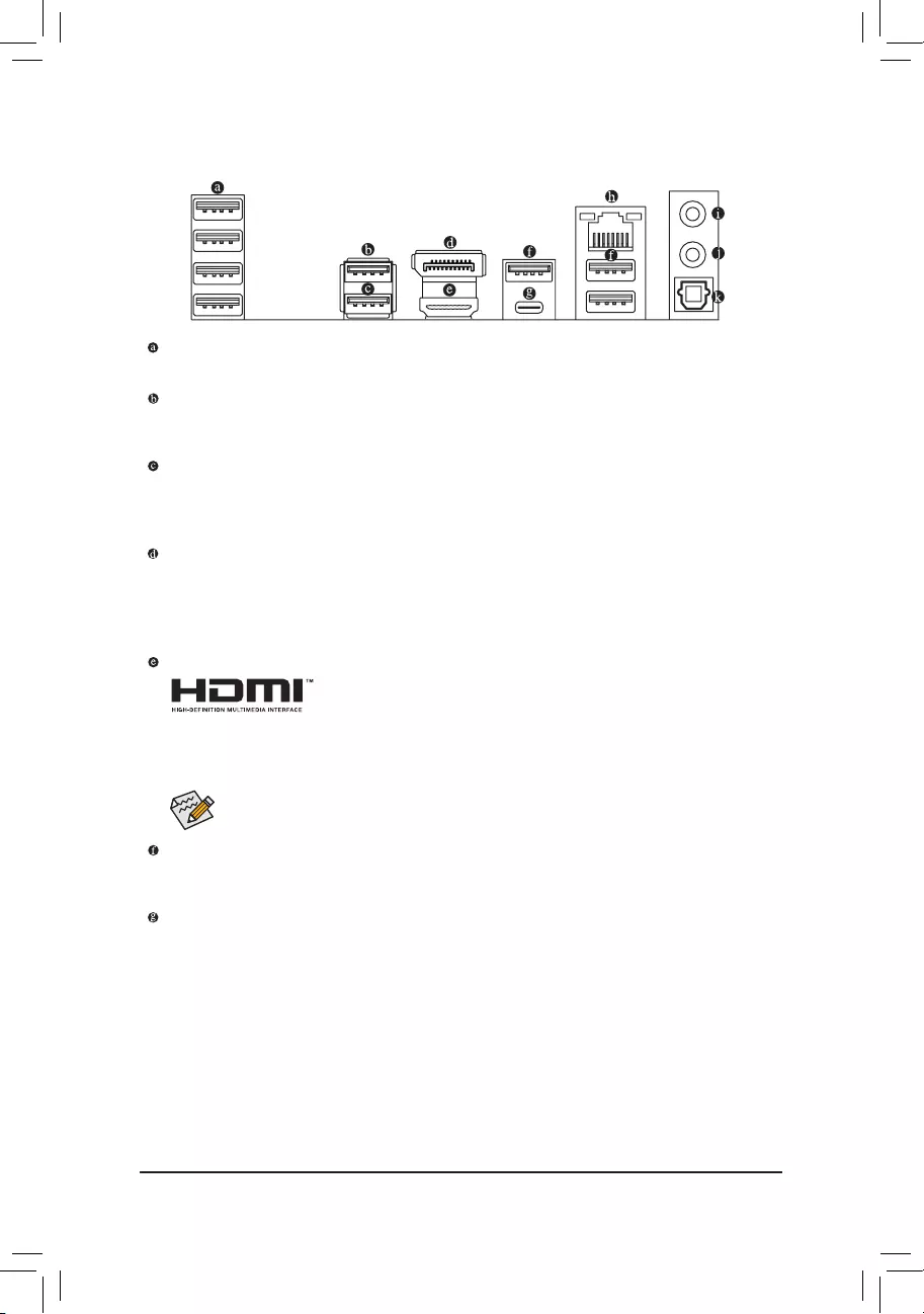
2-6 Back Panel Connectors
USB 2.0/1.1 Port
The USB port supports the USB 2.0/1.1 specication. Use this port for USB devices.
USB 3.2 Gen 2 Type-A Port (Red)
The USB 3.2 Gen 2 port supports the USB 3.2 Gen 2 specication and is compatible to the USB 3.2 Gen 1
and USB 2.0 specication. Use this port for USB devices.
USB 3.2 Gen 2 Type-A Port (Q-Flash Plus Port)
The USB 3.2 Gen 2 port supports the USB 3.2 Gen 2 specication and is compatible to the USB 3.2 Gen 1
and USB 2.0 specication. Use this port for USB devices. Before using Q-Flash Plus (Note), make sure to insert
the USB ash drive into this port rst.
DisplayPort
DisplayPort delivers high quality digital imaging and audio, supporting bi-directional audio transmission.
DisplayPort can support HDCP 2.3 content protection mechanisms. You can use this port to connect your
DisplayPort-supported monitor. Note: The DisplayPort Technology can support a maximum resolution of
4096×2304@60 Hz but the actual resolutions supported depend on the monitor being used.
HDMI 2.0 Port
The HDMI port supports HDCP 2.3 and Dolby TrueHD and DTS HD Master
Audio formats. It also supports up to 192KHz/24bit 7.1-channel LPCM audio
output. You can use this port to connect your HDMI-supported monitor. The maximum supported
resolution is 4096×2160@60 Hz, but the actual resolutions supported are dependent on the monitor
being used.
USB 3.2 Gen 1 Port
The USB 3.2 Gen 1 port supports the USB 3.2 Gen 1 specication and is compatible to the USB 2.0
specication. Use this port for USB devices.
USB Type-C® Port
The reversible USB port supports the USB 3.2 Gen 2×2 specication and is compatible to the USB 3.2
Gen 2, USB 3.2 Gen 1, and USB 2.0 specications. Use this port for USB devices.
After installing the HDMI/DisplayPort device, make sure to set the default sound playback device
to HDMI/DisplayPort. (The item name may differ depending on your operating system.)
(Note) To enable the Q-Flash Plus function, please navigate to the «Unique Features» page of GIGABYTE’s
website for more information.
— 18 —
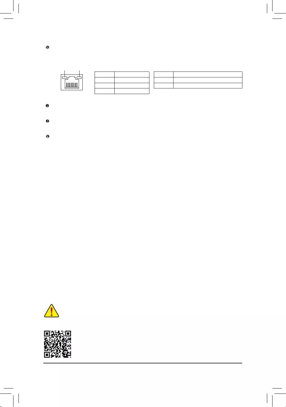
RJ-45 LAN Port
The Gigabit Ethernet LAN port provides Internet connection at up to 2.5 Gbps data rate. The following
describes the states of the LAN port LEDs.
Please visit GIGABYTE’s website for details on conguring the audio software.
Activity LED
Speed LED
LAN Port
Speed LED:
State Description
Orange 2.5 Gbps data rate
Green 1 Gbps data rate
Off 100 Mbps data rate
Activity LED:
State Description
Blinking Data transmission or receiving is occurring
Off No data transmission or receiving is occurring
Line Out
The line out jack.
Mic In
The Mic in jack.
Optical S/PDIF Out Connector
This connector provides digital audio out to an external audio system that supports digital optical audio.
Before using this feature, ensure that your audio system provides an optical digital audio in connector.
•When removing the cable connected to a back panel connector, rst remove the cable from your
device and then remove it from the motherboard.
•When removing the cable, pull it straight out from the connector. Do not rock it side to side to
prevent an electrical short inside the cable connector.
— 19 —
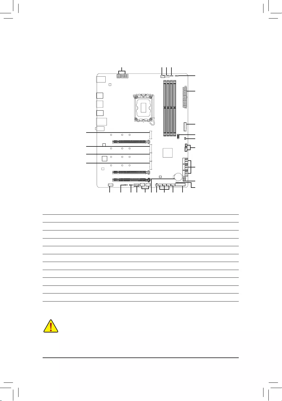
2-7 Internal Connectors
Read the following guidelines before connecting external devices:
•First make sure your devices are compliant with the connectors you wish to connect.
•Before installing the devices, be sure to turn off the devices and your computer. Unplug the power
cord from the power outlet to prevent damage to the devices.
•After installing the device and before turning on the computer, make sure the device cable has
been securely attached to the connector on the motherboard.
1) ATX_12V_2X2/ATX_12V_2X4
2) ATX
3) CPU_FAN
4) SYS_FAN1/2/3
5) SYS_FAN4_PUMP
6) CPU_OPT
7) SATA3 2/3/4/5/6/7
 D_LED1/D_LED2
9) LED_C1/LED_C2
10) M2A_CPU/M2P_SB/M2Q_SB/M2M_SB
11) F_PANEL
12) F_AUDIO
13) F_U32C
14) F_U32
15) F_USB1/F_USB2
16) SPI_TPM
17) THB_C1/THB_C2
18) CLR_CMOS
19) BAT
20) RST_SW/RST
21) QFLASH_PLUS
22) CPU/DRAM/VGA/BOOT
1119
14
13
2
9
17
7
15 412 16
81
8 9
18
20
36
10
10
10
10
521
22
— 20 —
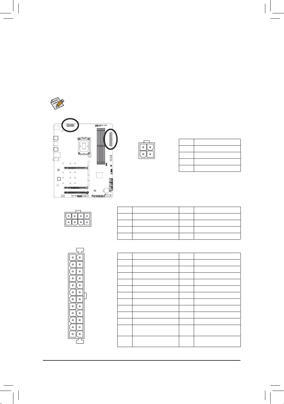
1/2) ATX_12V_2X2/ATX_12V_2X4/ATX (2×2, 2×4, 12V Power Connectors and 2×12 Main
Power Connector)
With the use of the power connector, the power supply can supply enough stable power to all the components
on the motherboard. Before connecting the power connector, rst make sure the power supply is turned
off and all devices are properly installed. The power connector possesses a foolproof design. Connect the
power supply cable to the power connector in the correct orientation.
The 12V power connector mainly supplies power to the CPU. If the 12V power connector is not connected,
the computer will not start.
To meet expansion requirements, it is recommended that a power supply that can withstand high
power consumption be used (500W or greater). If a power supply is used that does not provide the
required power, the result can lead to an unstable or unbootable system.
ATX_12V_2X4
ATX:
Pin No. Denition Pin No. Denition
1 3.3V 13 3.3V
2 3.3V 14 -12V
3 GND 15 GND
4 +5V 16 PS_ON (soft On/Off)
5 GND 17 GND
6 +5V 18 GND
7 GND 19 GND
8 Power Good 20 NC
9 5VSB (stand by +5V) 21 +5V
10 +12V 22 +5V
11 +12V (Only for 2×12-pin
ATX)
23 +5V (Only for 2×12-pin ATX)
12 3.3V (Only for 2×12-pin
ATX)
24 GND (Only for 2×12-pin
ATX)
41
85
131
2412
ATX
ATX_12V_2X2
21
3 4
ATX_12V_2X4:
Pin No. Denition Pin No. Denition
1GND (Only for 2×4-pin 12V) 5+12V (Only for 2×4-pin 12V)
2GND (Only for 2×4-pin 12V) 6+12V (Only for 2×4-pin 12V)
3 GND 7 +12V
4 GND 8 +12V
ATX_12V_2X2:
Pin No. Denition
1 GND
2 GND
3 +12V
4 +12V
— 21 —
•Be sure to connect fan cables to the fan headers to prevent your CPU and system from
overheating. Overheating may result in damage to the CPU or the system may hang.
•These fan headers are not conguration jumper blocks. Do not place a jumper cap on the headers.
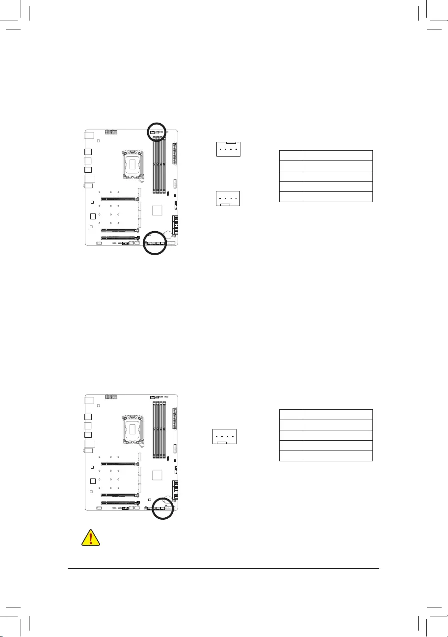
3/4) CPU_FAN/SYS_FAN1/2/3 (Fan Headers)
All fan headers on this motherboard are 4-pin. Most fan headers possess a foolproof insertion design.
When connecting a fan cable, be sure to connect it in the correct orientation (the black connector wire is
the ground wire). The speed control function requires the use of a fan with fan speed control design. For
optimum heat dissipation, it is recommended that a system fan be installed inside the chassis.
CPU_FAN
1
1
SYS_FAN1/SYS_FAN2/
SYS_FAN3
Pin No. Denition
1 GND
2 Voltage Speed Control
3 Sense
4 PWM Speed Control
5) SYS_FAN4_PUMP (System Fan/Water Cooling Pump Header)
The fan/pump header is 4-pin and possesses a foolproof insertion design. Most fan headers possess a
foolproof insertion design. When connecting a fan cable, be sure to connect it in the correct orientation
(the black connector wire is the ground wire). The speed control function requires the use of a fan with
fan speed control design. For optimum heat dissipation, it is recommended that a system fan be installed
inside the chassis. The header also provides speed control for a water cooling pump. Please navigate to
the «BIOS Setup» page of GIGABYTE’s website and search for «Smart Fan 6» for more information.
Pin No. Denition
1 GND
2 Voltage Speed Control
3 Sense
4 PWM Speed Control
1
— 22 —
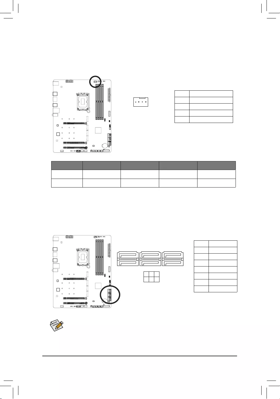
6) CPU_OPT (Water Cooling CPU Fan Header)
The fan header is 4-pin and possesses a foolproof insertion design. Most fan headers possess a foolproof
insertion design. When connecting a fan cable, be sure to connect it in the correct orientation (the black
connector wire is the ground wire). The speed control function requires the use of a fan with fan speed
control design.
1
Pin No. Denition
1 GND
2 Voltage Speed Control
3 Sense
4 PWM Speed Control
Connector CPU_FAN SYS_FAN1~3 SYS_FAN4_PUMP CPU_OPT
Maximum Current 2A 2A 2A 2A
Maximum Power 24W 24W 24W 24W
7) SATA3 2/3/4/5/6/7 (SATA 6Gb/s Connectors)
The SATA connectors conform to SATA 6Gb/s standard and are compatible with SATA 3Gb/s and SATA 1.5Gb/s
standard. Each SATA connector supports a single SATA device. The Intel® Chipset supports RAID 0, RAID 1,
RAID 5, and RAID 10. Please navigate to the «Conguring a RAID Set» page of GIGABYTE’s website for
instructions on conguring a RAID array.
Pin No. Denition
1 GND
2 TXP
3 TXN
4 GND
5 RXN
6 RXP
7 GND
SATA3 3 5 7
2 4 6
To enable hot-plugging for the SATA ports, please navigate to the «BIOS Setup» page of GIGABYTE’s
website and search for «SATA Conguration» for more information.
1
1
7
7
— 23 —
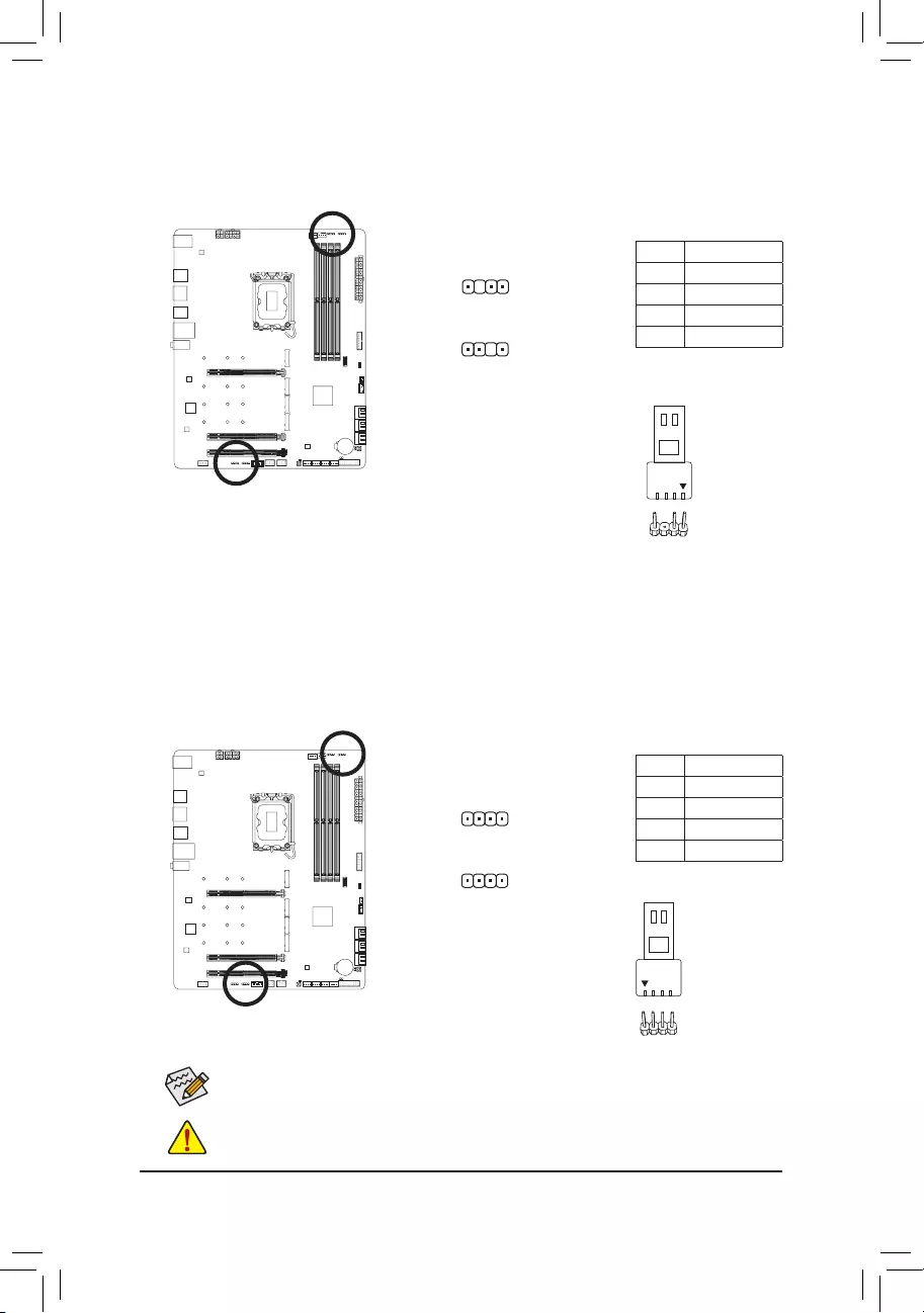
D_LED1/D_LED2 (Addressable LED Strip Headers)
The headers can be used to connect a standard 5050 addressable LED strip, with maximum power rating
of 5A (5V) and maximum number of 1000 LEDs.
1
D_LED1
Pin No. Denition
1 V (5V)
2 Data
3 No Pin
4 GND
Connect your addressable LED strip
to the header. The power pin (marked
with a triangle on the plug) of the LED strip must be connected to Pin 1 of
the addressable LED strip header. Incorrect connection may lead to the
damage of the LED strip.
1
D_LED2
Addressable LED
Strip
1
F_USB30 F_AUDIO(H)
DB_PORT
F_PANEL(NH) F_PANEL
(H61M-D2)
ACPI_CPT
(GA-IVB)
BIOS_PH
(GA-IVB)
SMB_CPT
(GA-IVB)
CLR_CMOS
CI
DIS_ME
GP15_CPT
(GA-IVB)
XDP_CPU
XDP_PCH
(GA-IVB)
TPM
w/housing
Voltage measurement module(X58A-OC)
PCIe power connector (SATA)(X58A-OC)
DIP
123
DIP
123
DIP
123
DIP
123
1
1
1
1
BIOS Switcher (X58A-OC)
PWM Switch (X58A-OC)
M_SATA
PWM Switch (SW1)(X79-UD7)
DIP
1 2 3 4 5
Voltage measurement points(G1.Sniper 3) BIOS Switcher (SW4)
GAIN
PCIe Control (Z87X-UP7)
ATX_12V_2X3
F_USB3 (Front Panel)
SATA_Express
SATA_Express
SATA_Express
PCIe/DIMM Control (Z97X-SOC Force)
M.2
MINI PCIE
THB_C
THB_C
M.2 Wi-Fi
M2_10G
Subzero
Sense
M2_10G with WIFI module
M2_WIFI
LED_IO (4-pin)
J_HDMI(NH)
OC_LED/OC_BT
M.2
MINI PCIE
U.2
SATA_SGP
LED_C(5-pin) SPDIF_O (4-pin)
BAT
USB20_OB
THB_C
THB_C1
F_USB31C
eDP F_USB30/31C
VROC
TPM_new
GPIOX8
M2_32G with GC-M2-U2
SPI_TPM
PW_SW
SYS_FAN
EXT_PWR
LED_DDR
9) LED_C1/LED_C2 (RGB LED Strip Headers)
The headers can be used to connect a standard 5050 RGB LED strip (12V/G/R/B), with maximum power
rating of 2A (12V) and maximum length of 2m.
Connect your RGB LED strip to the
header. The power pin (marked with a
triangle on the plug) of the LED strip must be connected to Pin 1 (12V) of
this header. Incorrect connection may lead to the damage of the LED strip.
Pin No. Denition
1 12V
2 G
3 R
4 B
1
LED_C2
1
LED_C1
Before installing the devices, be sure to turn off the devices and your computer. Unplug the power
cord from the power outlet to prevent damage to the devices.
For how to turn on/off the lights of the LED strip, please navigate to the «Unique Features» page
of GIGABYTE’s website.
12V
RGB LED Strip
1
— 24 —
10) M2A_CPU/M2P_SB/M2Q_SB/M2M_SB (M.2 Socket 3 Connectors)
There are two types of M.2 SSDs: M.2 SATA SSDs and M.2 PCIe SSDs. Be sure to verify which type of
M.2 SSDs is supported by the M.2 socket you want to use. Please note that an M.2 PCIe SSD cannot
be used to create a RAID set either with an M.2 SATA SSD or a SATA hard drive. Please navigate to the
«Conguring a RAID Set» page of GIGABYTE’s website for instructions on conguring a RAID array.
Follow the steps below to correctly install an M.2 SSD in the M.2 connector.
Step 1:
Locate the M.2 connector where you will install the M.2 SSD, use a screwdriver to unfasten the screw on
the heatsink and then remove the heatsink.
Step 2:
Locate the proper mounting hole based on the length of your M.2 SSD drive. If needed, move the standoff
to the desired mounting hole. Insert the M.2 SSD into the M.2 connector at an angle.
Step 3:
Press the M.2 SSD down and then use the included screw to secure it in the connector. Remove the
protective lm from the bottom of the heatsink. Then replace the heatsink and secure it to the original hole.
* Types of M.2 SSDs supported by each M.2 connector:
M.2 PCIe x4 SSD M.2 PCIe x2 SSD M.2 SATA SSD
M2A_CPU a a r
M2P_SB a a r
M2Q_SB a a r
M2M_SB aaa
F_USB30 F_AUDIO(H)
DB_PORT
F_PANEL(NH) F_PANEL
(H61M-D2)
ACPI_CPT
(GA-IVB)
BIOS_PH
(GA-IVB)
SMB_CPT
(GA-IVB)
CLR_CMOS
CI
DIS_ME
GP15_CPT
(GA-IVB)
XDP_CPU
XDP_PCH
(GA-IVB)
TPM
w/housing
Voltage measurement module(X58A-OC)
PCIe power connector (SATA)(X58A-OC)
DIP
123
DIP
123
DIP
123
DIP
123
1
1
1
1
BIOS Switcher (X58A-OC)
PWM Switch (X58A-OC)
M_SATA
PWM Switch (SW1)(X79-UD7)
DIP
1 2 3 4 5
Voltage measurement points(G1.Sniper 3) BIOS Switcher (SW4)
GAIN
PCIe Control (Z87X-UP7)
ATX_12V_2X3
F_USB3 (Front Panel)
SATA_Express
SATA_Express
SATA_Express
PCIe/DIMM Control (Z97X-SOC Force)
M.2
MINI PCIE
THB_C
THB_C
M.2 Wi-Fi
M2_10G
Subzero
Sense
M2_10G with WIFI module
M2_WIFI
LED_IO (4-pin)
J_HDMI(NH)
OC_LED/OC_BT
M.2
MINI PCIE
U.2
SATA_SGP
LED_C(5-pin) SPDIF_O (4-pin)
BAT
USB20_OB
THB_C
THB_C1
F_USB31C
eDP F_USB30/31C
VROC
TPM_new
GPIOX8
M2_32G with GC-M2-U2
SPI_TPM
PW_SW
SYS_FAN
EXT_PWR
LED_DDR
80110 60
M2A_CPU
M2P_SB
M2Q_SB
M2M_SB
If you want to install an operating system on an M.2 PCIe SSD, you need to install the Intel® RST
VMD Controller driver rst. Refer to Chapter 4 for more instructions.
— 25 —
•M2M_SB:
SATA3 2 SATA3 3 SATA3 4 SATA3 5 SATA3 6 SATA3 7
M.2 SATA SSD a a a a a a
M.2 PCIe SSD
rraaaa
No M.2 SSD Installed a a a a a a
a: Available, r: Not available
Connector
Type of
M.2 SSD
Installation Notices for the M.2 and SATA Connectors:
The availability of the SATA connectors may be affected by the type of device installed in the M.2 sockets. The
M2M_SB connector shares bandwidth with the SATA3 2, 3 connector. Refer to the following table for details.
•M2A_CPU/M2P_SB/M2Q_SB:
SATA3 2 SATA3 3 SATA3 4 SATA3 5 SATA3 6 SATA3 7
M.2 PCIe SSD
a a a a a a
No M.2 SSD Installed a a a a a a
a: Available, r: Not available
Connector
Type of
M.2 SSD
— 26 —
The front panel design may differ by chassis. A front panel module mainly consists of power switch,
reset switch, power LED, hard drive activity LED, speaker and etc. When connecting your chassis
front panel module to this header, make sure the wire assignments and the pin assignments are
matched correctly.
11) F_PANEL (Front Panel Header)
Connect the power switch, reset switch, speaker, chassis intrusion switch/sensor and system status indicator
on the chassis to this header according to the pin assignments below. Note the positive and negative pins
before connecting the cables.
•PW (Power Switch):
Connects to the power switch on the chassis front panel. You may congure the way to turn off your
system using the power switch (please navigate to the «BIOS Setup» page of GIGABYTE’s website and
search for «Soft-Off by PWR-BTTN» for more information).
•SPEAK (Speaker):
Connects to the speaker on the chassis front panel. The system reports system startup status by issuing
a beep code. One single short beep will be heard if no problem is detected at system startup.
•HD (Hard Drive Activity LED):
Connects to the hard drive activity LED on the chassis front panel. The LED is on when the hard drive
is reading or writing data.
•RES (Reset Switch):
Connects to the reset switch on the chassis front panel. Press the reset switch to restart the computer
if the computer freezes and fails to perform a normal restart.
•CI (Chassis Intrusion Header):
Connects to the chassis intrusion switch/sensor on the chassis that can detect if the chassis cover has
been removed. This function requires a chassis with a chassis intrusion switch/sensor.
•NC: No connection.
•PLED/PWR_LED (Power LED):
Connects to the power status indicator on the chassis front panel. The LED
is on when the system is operating. The LED is off when the system is in S3/
S4 sleep state or powered off (S5).
System Status LED
S0 On
S3/S4/S5 Off
NC
NC
Power LED
1
2
19
20
CI-
CI+
PWR_LED-
PWR_LED+
PLED-
PW-
SPEAK+
SPEAK-
PLED+
PW+
Power LED
HD-
RES+
HD+
RES-
Hard Drive
Activity LED
Reset
Switch Chassis Intrusion
Header
Power Switch Speaker
PWR_LED-
— 27 —
12) F_AUDIO (Front Panel Audio Header)
The front panel audio header supports High Denition audio (HD). You may connect your chassis front
panel audio module to this header. Make sure the wire assignments of the module connector match the
pin assignments of the motherboard header. Incorrect connection between the module connector and the
motherboard header will make the device unable to work or even damage it.
Pin No. Denition
1 MIC2_L
2 GND
3 MIC2_R
4 NC
5 LINE2_R
6 Sense
7 GND
8 No Pin
9 LINE2_L
10 Sense
F_USB30 F_AUDIO(H)
DB_PORT
F_PANEL(NH) F_PANEL
(H61M-D2)
ACPI_CPT
(GA-IVB)
BIOS_PH
(GA-IVB)
SMB_CPT
(GA-IVB)
CLR_CMOS
CI
DIS_ME
GP15_CPT
(GA-IVB)
XDP_CPU
XDP_PCH
(GA-IVB)
TPM
w/housing
Voltage measurement module(X58A-OC)
PCIe power connector (SATA)(X58A-OC)
DIP
123
DIP
123
DIP
123
DIP
123
1
1
1
1
BIOS Switcher (X58A-OC)
PWM Switch (X58A-OC)
M_SATA
PWM Switch (SW1)(X79-UD7)
DIP
1 2 3 4 5
Voltage measurement points(G1.Sniper 3) BIOS Switcher (SW4)
GAIN
PCIe Control (Z87X-UP7)
ATX_12V_2X3
F_USB3 (Front Panel)
SATA_Express
SATA_Express
SATA_Express
PCIe/DIMM Control (Z97X-SOC Force)
M.2
MINI PCIE
THB_C
THB_C
M.2 Wi-Fi
M2_10G
Subzero
Sense
M2_10G with WIFI module
M2_WIFI
LED_IO (4-pin)
J_HDMI(NH)
OC_LED/OC_BT
M.2
MINI PCIE
U.2
SATA_SGP
LED_C(5-pin) SPDIF_O (4-pin)
BAT
USB20_OB
THB_C
THB_C1
F_USB31C
eDP F_USB30/31C
VROC
TPM_new
GPIOX8
M2_32G with GC-M2-U2
SPI_TPM
PW_SW
SYS_FAN
EXT_PWR
LED_DDR
91
10 2
Some chassis provide a front panel audio module that has separated connectors on each wire
instead of a single plug. For information about connecting the front panel audio module that has
different wire assignments, please contact the chassis manufacturer.
13) F_U32C (USB Type-C® Header with USB 3.2 Gen 2 Support)
The header conforms to USB 3.2 Gen 2 specication and can provide one USB port.
Pin No. Denition Pin No. Denition
1 VBUS 11 VBUS
2 TX1+ 12 TX2+
3 TX1- 13 TX2-
4 GND 14 GND
5 RX1+ 15 RX2+
6 RX1- 16 RX2-
7 VBUS 17 GND
8 CC1 18 D-
9 SBU1 19 D+
10 SBU2 20 CC2
F_USB30 F_AUDIO(H)
DB_PORT
F_PANEL(NH) F_PANEL
(H61M-D2)
ACPI_CPT
(GA-IVB)
BIOS_PH
(GA-IVB)
SMB_CPT
(GA-IVB)
CLR_CMOS
CI
DIS_ME
GP15_CPT
(GA-IVB)
XDP_CPU
XDP_PCH
(GA-IVB)
TPM
w/housing
Voltage measurement module(X58A-OC)
PCIe power connector (SATA)(X58A-OC)
DIP
123
DIP
123
DIP
123
DIP
123
1
1
1
1
BIOS Switcher (X58A-OC)
PWM Switch (X58A-OC)
M_SATA
PWM Switch (SW1)(X79-UD7)
DIP
1 2 3 4 5
Voltage measurement points(G1.Sniper 3) BIOS Switcher (SW4)
GAIN
PCIe Control (Z87X-UP7)
ATX_12V_2X3
F_USB3 (Front Panel)
SATA_Express
SATA_Express
SATA_Express
PCIe/DIMM Control (Z97X-SOC Force)
M.2
MINI PCIE
THB_C
THB_C
M.2 Wi-Fi
M2_10G
Subzero
Sense
M2_10G with WIFI module
M2_WIFI
LED_IO (4-pin)
J_HDMI(NH)
OC_LED/OC_BT
M.2
MINI PCIE
U.2
SATA_SGP
LED_C(5-pin) SPDIF_O (4-pin)
BAT
USB20_OB
THB_C
THB_C1
F_USB31C
eDP F_USB30/31C
VROC
TPM_new
GPIOX8
M2_32G with GC-M2-U2
SPI_TPM
PW_SW
SYS_FAN
EXT_PWR
LED_DDR
20
10 11
1
— 28 —
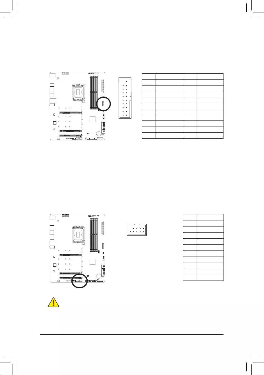
14) F_U32 (USB 3.2 Gen 1 Header)
The header conforms to USB 3.2 Gen 1 and USB 2.0 specication and can provide two USB ports. For
purchasing the optional 3.5″ front panel that provides two USB 3.2 Gen 1 ports, please contact the local
dealer.
Pin No. Denition Pin No. Denition
1VBUS 11 D2+
2 SSRX1- 12 D2-
3 SSRX1+ 13 GND
4 GND 14 SSTX2+
5 SSTX1- 15 SSTX2-
6 SSTX1+ 16 GND
7 GND 17 SSRX2+
8 D1- 18 SSRX2-
9 D1+ 19 VBUS
10 NC 20 No Pin
F_USB30 F_AUDIO(H)
DB_PORT
F_PANEL(NH) F_PANEL
(H61M-D2)
ACPI_CPT
(GA-IVB)
BIOS_PH
(GA-IVB)
SMB_CPT
(GA-IVB)
CLR_CMOS
CI
DIS_ME
GP15_CPT
(GA-IVB)
XDP_CPU
XDP_PCH
(GA-IVB)
TPM
w/housing
Voltage measurement module(X58A-OC)
PCIe power connector (SATA)(X58A-OC)
DIP
123
DIP
123
DIP
123
DIP
123
1
1
1
1
BIOS Switcher (X58A-OC)
PWM Switch (X58A-OC)
M_SATA
PWM Switch (SW1)(X79-UD7)
DIP
1 2 3 4 5
Voltage measurement points(G1.Sniper 3) BIOS Switcher (SW4)
GAIN
PCIe Control (Z87X-UP7)
ATX_12V_2X3
F_USB3 (Front Panel)
SATA_Express
SATA_Express
SATA_Express
PCIe/DIMM Control (Z97X-SOC Force)
M.2
MINI PCIE
THB_C
THB_C
M.2 Wi-Fi
M2_10G
Subzero
Sense
M2_10G with WIFI module
M2_WIFI
LED_IO (4-pin)
J_HDMI(NH)
OC_LED/OC_BT
M.2
MINI PCIE
U.2
SATA_SGP
LED_C(5-pin) SPDIF_O (4-pin)
BAT
USB20_OB
THB_C
THB_C1
F_USB31C
eDP F_USB30/31C
VROC
TPM_new
GPIOX8
M2_32G with GC-M2-U2
SPI_TPM
PW_SW
SYS_FAN
EXT_PWR
LED_DDR
20 1
1011
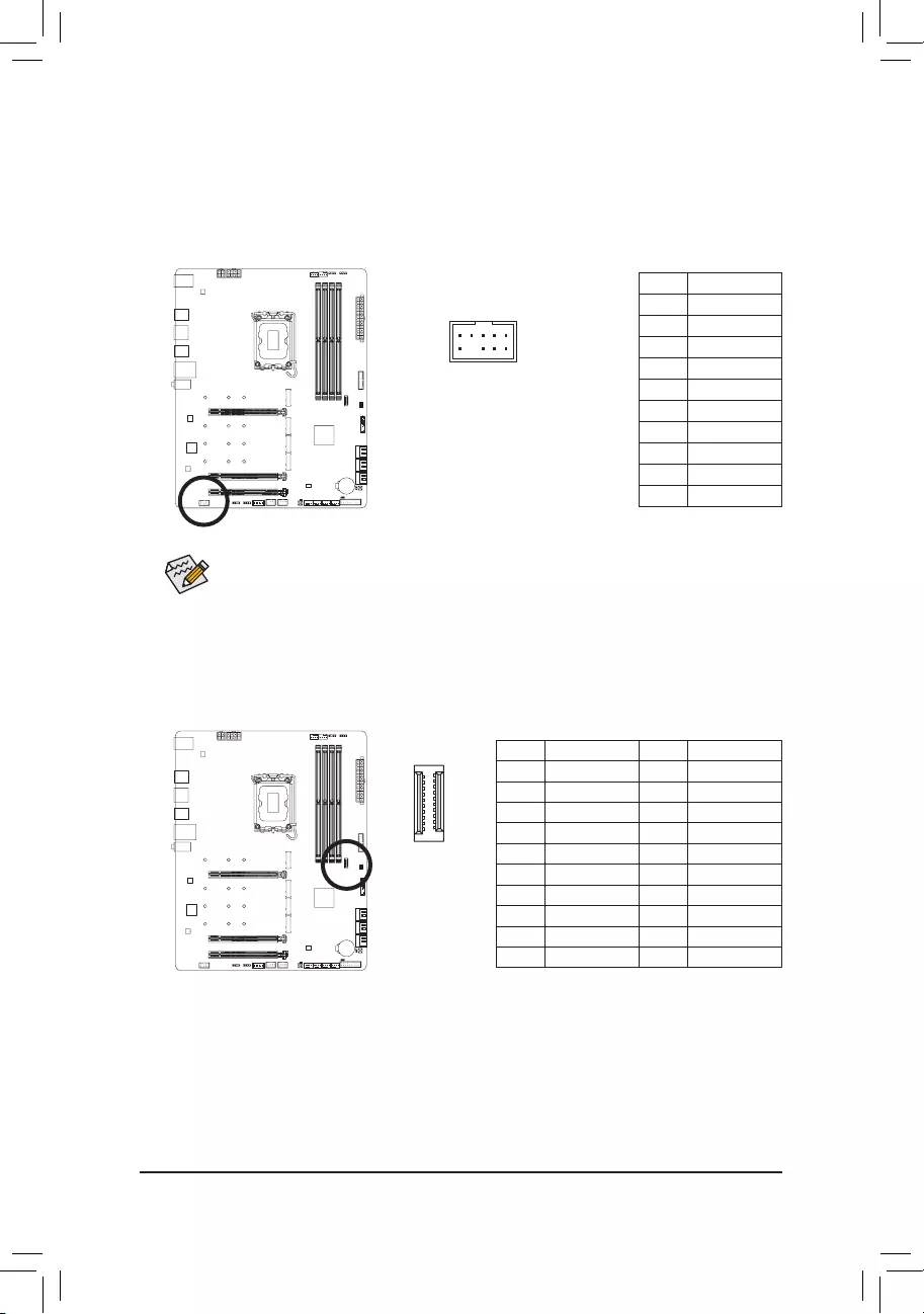
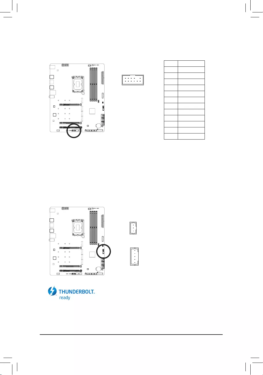
15) F_USB1/F_USB2 (USB 2.0/1.1 Headers)
The headers conform to USB 2.0/1.1 specication. Each USB header can provide two USB ports via an
optional USB bracket. For purchasing the optional USB bracket, please contact the local dealer.
Pin No. Denition
1 Power (5V)
2 Power (5V)
3 USB DX-
4 USB DY—
5 USB DX+
6 USB DY+
7 GND
8 GND
9 No Pin
10 NC
10
9
2
1
•Do not plug the IEEE 1394 bracket (2×5-pin) cable into the USB 2.0/1.1 header.
•Prior to installing the USB bracket, be sure to turn off your computer and unplug the power cord
from the power outlet to prevent damage to the USB bracket.
— 29 —
Pin No. Denition
1Data Output
2Power (3.3V)
3No Pin
4NC
5Data Input
6CLK
7Chip Select
8GND
9IRQ
10 NC
11 NC
12 RST
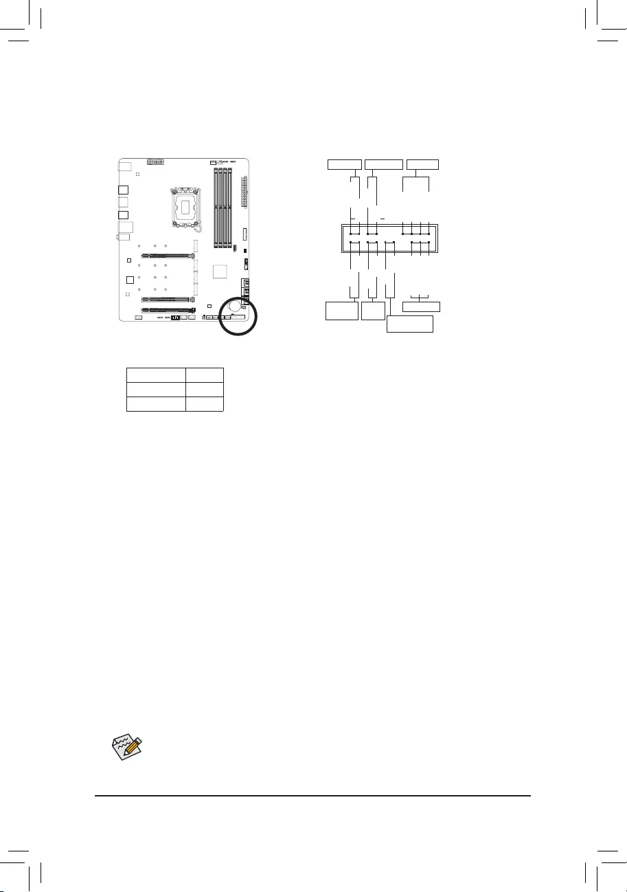
16) SPI_TPM (Trusted Platform Module Header)
You may connect an SPI TPM (Trusted Platform Module) to this header.
17) THB_C1/THB_C2 (Thunderbolt™ Add-in Card Connectors)
The connectors are used to connect to a GIGABYTE Thunderbolt™ add-in card.
Supports a Thunderbolt™ add-in card.
F_USB30 F_AUDIO(H)
DB_PORT
F_PANEL(NH) F_PANEL
(H61M-D2)
ACPI_CPT
(GA-IVB)
BIOS_PH
(GA-IVB)
SMB_CPT
(GA-IVB)
CLR_CMOS
CI
DIS_ME
GP15_CPT
(GA-IVB)
XDP_CPU
XDP_PCH
(GA-IVB)
TPM
w/housing
Voltage measurement module(X58A-OC)
PCIe power connector (SATA)(X58A-OC)
DIP
123
DIP
123
DIP
123
DIP
123
1
1
1
1
BIOS Switcher (X58A-OC)
PWM Switch (X58A-OC)
M_SATA
PWM Switch (SW1)(X79-UD7)
DIP
1 2 3 4 5
Voltage measurement points(G1.Sniper 3) BIOS Switcher (SW4)
GAIN
PCIe Control (Z87X-UP7)
ATX_12V_2X3
F_USB3 (Front Panel)
SATA_Express
SATA_Express
SATA_Express
PCIe/DIMM Control (Z97X-SOC Force)
M.2
MINI PCIE
THB_C
THB_C
M.2 Wi-Fi
M2_10G
Subzero
Sense
M2_10G with WIFI module
M2_WIFI
LED_IO (4-pin)
J_HDMI(NH)
OC_LED/OC_BT
M.2
MINI PCIE
U.2
SATA_SGP
LED_C(5-pin) SPDIF_O (4-pin)
BAT
USB20_OB
THB_C
THB_C1
F_USB31C
eDP F_USB30/31C
VROC
TPM_new
GPIOX8
M2_32G with GC-M2-U2
SPI_TPM
PW_SW
SYS_FAN
EXT_PWR
LED_DDR
1
1
THB_C2
THB_C1
12
11
2
1
F_USB30 F_AUDIO(H)
DB_PORT
F_PANEL(NH) F_PANEL
(H61M-D2)
ACPI_CPT
(GA-IVB)
BIOS_PH
(GA-IVB)
SMB_CPT
(GA-IVB)
CLR_CMOS
CI
DIS_ME
GP15_CPT
(GA-IVB)
XDP_CPU
XDP_PCH
(GA-IVB)
TPM
w/housing
Voltage measurement module(X58A-OC)
PCIe power connector (SATA)(X58A-OC)
DIP
123
DIP
123
DIP
123
DIP
123
1
1
1
1
BIOS Switcher (X58A-OC)
PWM Switch (X58A-OC)
M_SATA
PWM Switch (SW1)(X79-UD7)
DIP
1 2 3 4 5
Voltage measurement points(G1.Sniper 3) BIOS Switcher (SW4)
GAIN
PCIe Control (Z87X-UP7)
ATX_12V_2X3
F_USB3 (Front Panel)
SATA_Express
SATA_Express
SATA_Express
PCIe/DIMM Control (Z97X-SOC Force)
M.2
MINI PCIE
THB_C
THB_C
M.2 Wi-Fi
M2_10G
Subzero
Sense
M2_10G with WIFI module
M2_WIFI
LED_IO (4-pin)
J_HDMI(NH)
OC_LED/OC_BT
M.2
MINI PCIE
U.2
SATA_SGP
LED_C(5-pin) SPDIF_O (4-pin)
BAT
USB20_OB
THB_C
THB_C1
F_USB31C
eDP F_USB30/31C
VROC
TPM_new
GPIOX8
M2_32G with GC-M2-U2
SPI_TPM
PW_SW
SYS_FAN
EXT_PWR
LED_DDR
— 30 —
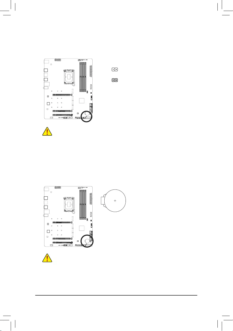
18) CLR_CMOS (Clear CMOS Jumper)
Use this jumper to clear the BIOS conguration and reset the CMOS values to factory defaults. To clear
the CMOS values, use a metal object like a screwdriver to touch the two pins for a few seconds.
•Always turn off your computer and unplug the power cord from the power outlet before clearing
the CMOS values.
•After system restart, go to BIOS Setup to load factory defaults (select Load Optimized Defaults) or
manually congure the BIOS settings (please navigate to the «BIOS Setup» page of GIGABYTE’s
website for more information).
Open: Normal
Short: Clear CMOS Values
19) BAT (Battery)
The battery provides power to keep the values (such as BIOS congurations, date, and time information)
in the CMOS when the computer is turned off. Replace the battery when the battery voltage drops to a low
level, or the CMOS values may not be accurate or may be lost.
You may clear the CMOS values by removing the battery:
1. Turn off your computer and unplug the power cord.
2. Gently remove the battery from the battery holder and wait for one minute.
(Or use a metal object like a screwdriver to touch the positive and negative
terminals of the battery holder, making them short for 5 seconds.)
3. Replace the battery.
4. Plug in the power cord and restart your computer.
•Always turn off your computer and unplug the power cord before replacing the battery.
•Replace the battery with an equivalent one. Damage to your devices may occur if the battery is
replaced with an incorrect model.
•Contact the place of purchase or local dealer if you are not able to replace the battery by yourself
or uncertain about the battery model.
•When installing the battery, note the orientation of the positive side (+) and the negative side (-)
of the battery (the positive side should face up).
•Used batteries must be handled in accordance with local environmental regulations.
— 31 —
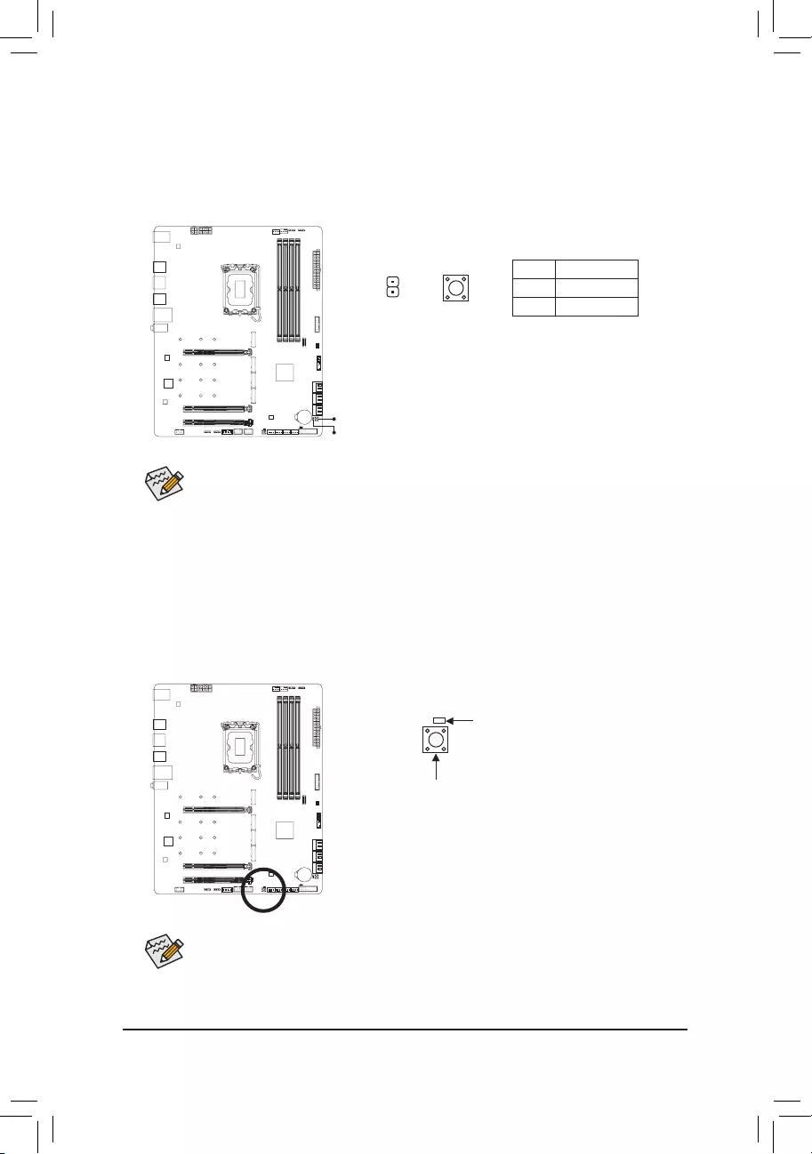
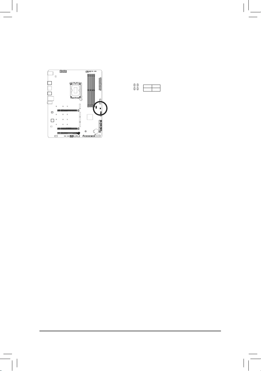
20) RST_SW/RST (Reset Button/Reset Jumper)
The reset button (RST_SW) allows users to quickly turn on/off the computer in an open-case environment
when they want to change hardware components or conduct hardware testing. The reset jumper (RST)
can connect to the reset switch on the chassis front panel. Press the reset switch to restart the computer
if the computer freezes and fails to perform a normal restart.
Pin No. Denition
1 Reset
2 GND
The reset button (RST_SW)/rest jumper (RST) provides you with several functions to use. To remap
the button to perform different tasks, please navigate to the «BIOS Setup» page of GIGABYTE’s
website and search for «RST_SW (MULTIKEY)» for more information.
RST_SW
RST
21) QFLASH_PLUS (Q-Flash Plus Button)
Q-Flash Plus allows you to update the BIOS when your system is off (S5 shutdown state). Save the latest
BIOS on a USB thumb drive and plug it into the dedicated port, and then you can now ash the BIOS
automatically by simply pressing the Q-Flash Plus button. The QFLED will ash when the BIOS matching
and ashing activities start and will stop ashing when the main BIOS ashing is complete.
To enable the Q-Flash Plus function, please navigate to the «Unique Features» page of GIGABYTE’s
website for more information.
1
RST
QFLASH_PLUS
QFLED
RST_SW
— 32 —
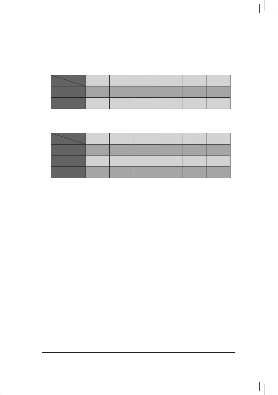
22) CPU/DRAM/VGA/BOOT (Status LEDs)
The status LEDs show whether the CPU, memory, graphics card, and operating system are working
properly after system power-on. If the CPU/DRAM/VGA LED is on, that means the corresponding device
is not working normally; if the BOOT LED is on, that means you haven’t entered the operating system yet.
CPU: CPU status LED
DRAM: Memory status LED
VGA: Graphics card status LED
BOOT: Operating system status LED
DRAM BOOT
CPU VGA
F_USB30 F_AUDIO(H)
DB_PORT
F_PANEL(NH) F_PANEL
(H61M-D2)
ACPI_CPT
(GA-IVB)
BIOS_PH
(GA-IVB)
SMB_CPT
(GA-IVB)
CLR_CMOS
CI
DIS_ME
GP15_CPT
(GA-IVB)
XDP_CPU
XDP_PCH
(GA-IVB)
TPM
w/housing
Voltage measurement module(X58A-OC)
PCIe power connector (SATA)(X58A-OC)
DIP
123
DIP
123
DIP
123
DIP
123
1
1
1
1
BIOS Switcher (X58A-OC)
PWM Switch (X58A-OC)
M_SATA
PWM Switch (SW1)(X79-UD7)
DIP
1 2 3 4 5
Voltage measurement points(G1.Sniper 3) BIOS Switcher (SW4)
GAIN
PCIe Control (Z87X-UP7)
ATX_12V_2X3
F_USB3 (Front Panel)
SATA_Express
SATA_Express
SATA_Express
PCIe/DIMM Control (Z97X-SOC Force)
M.2
MINI PCIE
THB_C
THB_C
M.2 Wi-Fi
M2_10G
Subzero
Sense
M2_10G with WIFI module
M2_WIFI
LED_IO (4-pin)
J_HDMI(NH)
OC_LED/OC_BT
M.2
MINI PCIE
U.2
SATA_SGP
LED_C(5-pin) SPDIF_O (4-pin)
BAT
USB20_OB
THB_C
THB_C1
F_USB31C
eDP F_USB30/31C
VROC
TPM_new
GPIOX8
M2_32G with GC-M2-U2
SPI_TPM
PW_SW
SYS_FAN
EXT_PWR
LED_DDR
— 33 —
BIOS (Basic Input and Output System) records hardware parameters of the system in the CMOS on the
motherboard. Its major functions include conducting the Power-On Self-Test (POST) during system startup,
saving system parameters and loading operating system, etc. BIOS includes a BIOS Setup program that allows
the user to modify basic system conguration settings or to activate certain system features.
When the power is turned off, the battery on the motherboard supplies the necessary power to the CMOS to
keep the conguration values in the CMOS.
To access the BIOS Setup program, press the <Delete> key during the POST when the power is turned on.
To upgrade the BIOS, use either the GIGABYTE Q-Flash or @BIOS utility.
•Q-Flash allows the user to quickly and easily upgrade or back up BIOS without entering the operating system.
•@BIOS is a Windows-based utility that searches and downloads the latest version of BIOS from the Internet
and updates the BIOS.
For instructions on using the Q-Flash and @BIOS utilities, please navigate to the «Unique Features» page of
GIGABYTE’s website and search for «BIOS Update Utilities.»
Chapter 3 BIOS Setup
•Because BIOS ashing is potentially risky, if you do not encounter problems using the current
version of BIOS, it is recommended that you not ash the BIOS. To ash the BIOS, do it with
caution. Inadequate BIOS ashing may result in system malfunction.
•It is recommended that you not alter the default settings (unless you need to) to prevent system
instability or other unexpected results. Inadequately altering the settings may result in system’s
failure to boot. If this occurs, try to clear the CMOS values and reset the board to default values.
•Refer to the introductions of the battery/clear CMOS jumper in Chapter 2 or navigate to the «BIOS
Setup» page of GIGABYTE’s website and search for «Load Optimized Defaults» for how to clear
the CMOS values.
Please visit GIGABYTE’s website for details on conguring BIOS Setup.
— 34 —
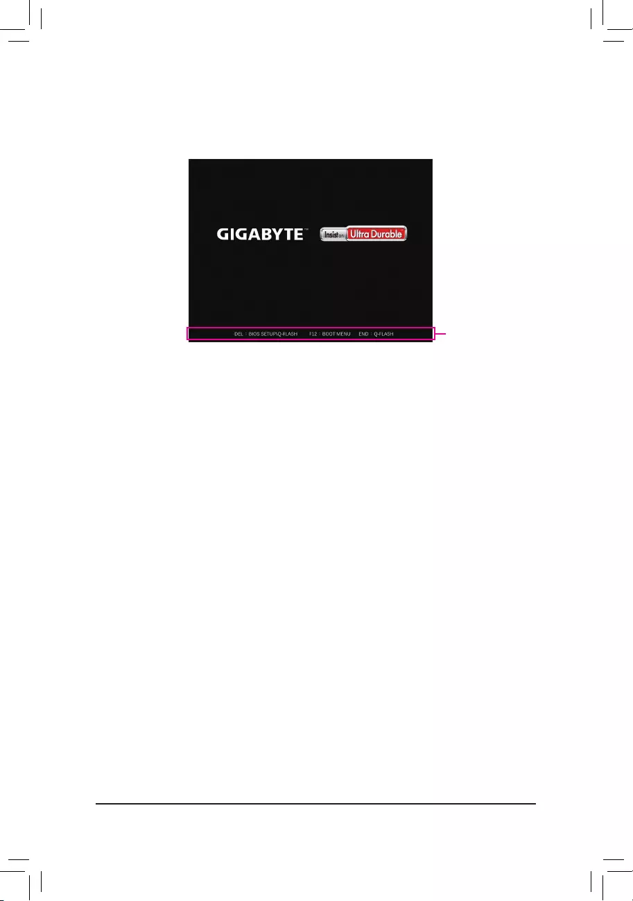
Startup Screen:
Function Keys:
<DEL>: BIOS SETUP\Q-FLASH
Press the <Delete> key to enter BIOS Setup or to access the Q-Flash utility in BIOS Setup.
<F12>: BOOT MENU
Boot Menu allows you to set the rst boot device without entering BIOS Setup. In Boot Menu, use the up
arrow key <h> or the down arrow key <i> to select the rst boot device, then press <Enter> to accept.
The system will boot from the device immediately.
Note: The setting in Boot Menu is effective for one time only. After system restart, the device boot order
will still be based on BIOS Setup settings.
<END>: Q-FLASH
Press the <End> key to access the Q-Flash utility directly without having to enter BIOS Setup rst.
Function Keys
The following startup Logo screen will appear when the computer boots.
— 35 —
Chapter 4 Installing the Operating System and Drivers
4-1 Operating System Installation
With the correct BIOS settings, you are ready to install the operating system.
If you want to install an operating system on an M.2 PCIe SSD or a RAID volume, you need to install the Intel®
RST VMD Controller driver rst during the OS installation process. Refer to the steps below:
Step 1:
Go to GIGABYTE’s website, browse to the motherboard model’s web page, download the Intel SATA Preinstall
driver le on the Support\Download\SATA RAID/AHCI page, unzip the le and copy the les to your USB
thumb drive.
Step 2:
Boot from the Windows setup disc and perform standard OS installation steps. When the screen requesting you
to load the driver appears, select Browse.
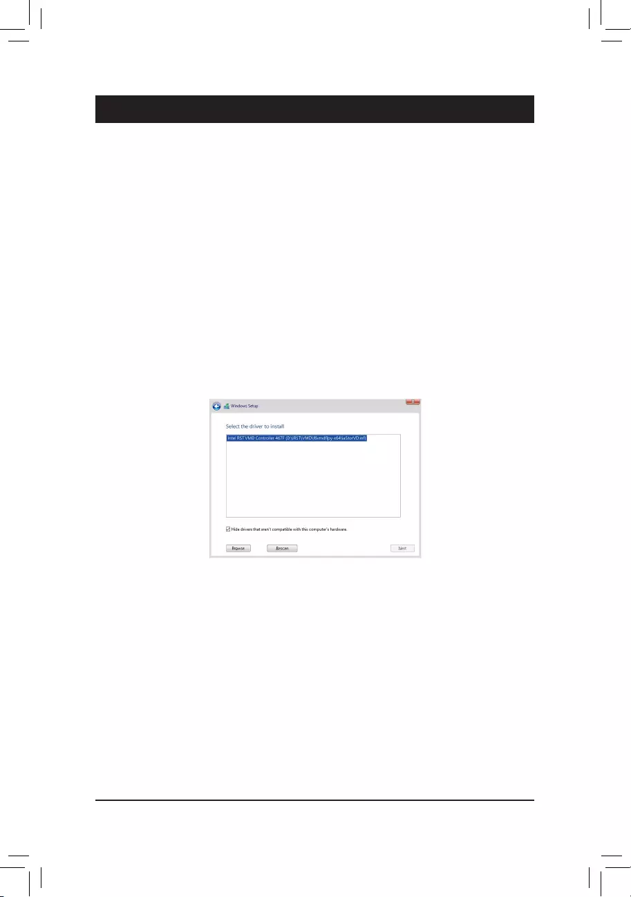
Step 3:
Insert the USB thumb drive and then browse to the location of the driver. When a screen as shown below
appears, select Intel RST VMD Controller 467F and click Next to load the driver and continue the OS installation.
— 36 —
4-2 Drivers Installation
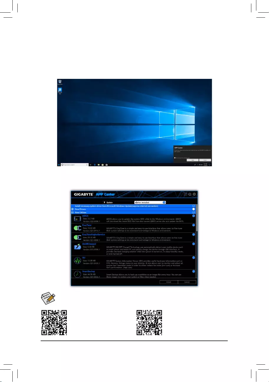
After you install the operating system, a dialog box will appear on the bottom-right corner of the desktop asking
if you want to download and install the drivers and GIGABYTE applications via APP Center. Click Install to
proceed with the installation. (In BIOS Setup, make sure Settings\IO Ports\APP Center Download & Install
Conguration\APP Center Download & Install is set to Enabled.)
Please visit GIGABYTE’s website for
more software information.
Please visit GIGABYTE’s website for
more troubleshooting information.
Before the installation, make sure the system is connected to the Internet.
When the End User License Agreement dialog box appears, press <Accept> to install APP Center. On the APP
Center screen, select the drivers and applications you want to install and click Install.
— 37 —
Chapter 5 Appendix
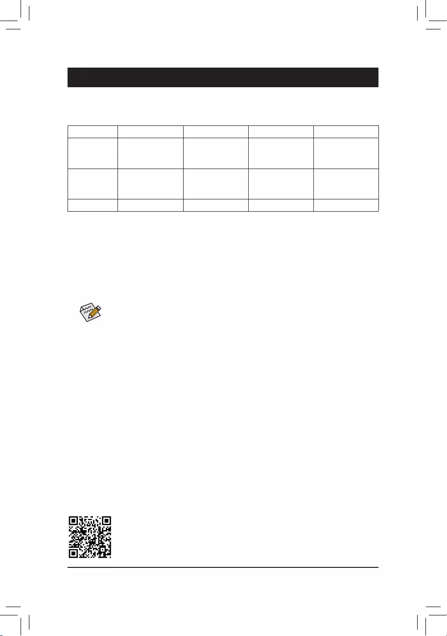
5-1 ConguringaRAIDSet
Before you begin, please prepare the following items:
This motherboard supports RAID 0, RAID 1, RAID 5, and RAID 10. Prepare the correct number of hard drives
as indicated in the table above before conguring a RAID array.
•SATA hard drives or SSDs. To ensure optimal performance, it is recommended that you use two hard drives
with identical model and capacity.
•Windows setup disc.
•An Internet connected computer.
•A USB thumb drive.
Please visit GIGABYTE’s website for details on conguring a RAID array.
•An M.2 PCIe SSD cannot be used to set up a RAID set either with an M.2 SATA SSD or a SATA
hard drive.
•Refer to «Internal Connectors,» for the installation notices for the M.2 and SATA connectors.
RAID Levels
RAID 0 RAID 1 RAID 5 RAID 10
Minimum
Number of Hard
Drives
≥2 2≥3 4
Array Capacity
Number of hard
drives * Size of the
smallest drive
Size of the smallest
drive
(Number of hard
drives -1) * Size of
the smallest drive
(Number of hard
drives/2) * Size of the
smallest drive
Fault Tolerance No Yes Yes Yes
— 38 —
Regulatory Notices
United States of America, Federal Communications Commission Statement
This equipment has been tested and found to comply with the limits for a
Class B digital device, pursuant to Part 15 of the FCC Rules. These limits
are designed to provide reasonable protection against harmful interference
in a residential installation. This equipment generates, uses and can radiate
radio frequency energy and, if not installed and used in accordance with
manufacturer’s instructions, may cause harmful interference to radio
communications. However, there is no guarantee that interference will
not occur in a particular installation. If this equipment does cause harmful
interference to radio or television reception, which can be determined by
turning the equipment off and on, the user is encouraged to try to correct
the interference by one or more of the following measures:
•Reorient or relocate the receiving antenna.
•Increase the separation between the equipment and receiver.
•Connect the equipment to an outlet on a circuit different from that to
which the receiver is connected.
•Consult the dealer or an experienced radio/TV technician for help.
Canadian Department of Communications Statement
This digital apparatus does not exceed the Class B limits for radio
noise emissions from digital apparatus set out in the Radio Interference
Regulations of the Canadian Department of Communications. This class
B digital apparatus complies with Canadian ICES-003.
Avis de conformité à la réglementation d’Industrie Canada
Cet appareil numérique de la classe B est conforme à la norme NMB-
003 du Canada.
European Union (EU) CE Declaration of Conformity
This device complies with the following directives: Electromagnetic
Compatibility Directive 2014/30/EU, Low-voltage Directive 2014/35/
EU, RoHS directive (recast) 2011/65/EU & the 2015/863 Statement.
This product has been tested and found to comply with all essential
requirements of the Directives.
European Union (EU) RoHS (recast) Directive 2011/65/EU & the
European Commission Delegated Directive (EU) 2015/863 Statement
GIGABYTE products have not intended to add and safe from hazardous
substances (Cd, Pb, Hg, Cr+6, PBDE, PBB, DEHP, BBP, DBP and DIBP).
The parts and components have been carefully selected to meet RoHS
requirement. Moreover, we at GIGABYTE are continuing our efforts to
develop products that do not use internationally banned toxic chemicals.
European Union (EU) Community Waste Electrical & Electronic
Equipment (WEEE) Directive Statement
GIGABYTE will fulll the national laws as interpreted from the 2012/19/
EU WEEE (Waste Electrical and Electronic Equipment) (recast) directive.
The WEEE Directive species the treatment, collection, recycling and
disposal of electric and electronic devices and their components. Under
the Directive, used equipment must be marked, collected separately, and
disposed of properly.
WEEE Symbol Statement
The symbol shown below is on the product or on its
packaging, which indicates that this product must not be
disposed of with other waste. Instead, the device should be
taken to the waste collection centers for activation of the
treatment, collection, recycling and disposal procedure.
For more information about where you can drop off your waste equipment
for recycling, please contact your local government ofce, your household
waste disposal service or where you purchased the product for details of
environmentally safe recycling.
End of Life Directives-Recycling
The symbol shown below is on the product or on its packaging,
which indicates that this product must not be disposed of with
other waste. Instead, the device should be taken to the waste
collection centers for activation of the treatment, collection,
recycling and disposal procedure.
Déclaration de Conformité aux Directives de l’Union européenne (UE)
Cet appareil portant la marque CE est conforme aux directives de l’UE
suivantes: directive Compatibilité Electromagnétique 2014/30/UE, directive
Basse Tension 2014/35/UE et directive RoHS II 2011/65/UE. La conformité
à ces directives est évaluée sur la base des normes européennes
harmonisées applicables.
European Union (EU) CE-Konformitätserklärung
Dieses Produkte mit CE-Kennzeichnung erfüllen folgenden EU-Richtlinien:
EMV-Richtlinie 2014/30/EU, Niederspannungsrichtlinie 2014/30/EU und
RoHS-Richtlinie 2011/65/EU erfüllt. Die Konformität mit diesen Richtlinien
wird unter Verwendung der entsprechenden Standards zurEuropäischen
Normierung beurteilt.
CE declaração de conformidade
Este produto com a marcação CE estão em conformidade com das
seguintes Diretivas UE: Diretiva Baixa Tensão 2014/35/EU; Diretiva CEM
2014/30/EU; Diretiva RSP 2011/65/UE. A conformidade com estas diretivas
é vericada utilizando as normas europeias harmonizadas.
CE Declaración de conformidad
Este producto que llevan la marca CE cumplen con las siguientes
Directivas de la Unión Europea: Directiva EMC (2014/30/EU), Directiva
de bajo voltaje (2014/35/EU), Directiva RoHS (recast) (2011/65/EU).
El cumplimiento de estas directivas se evalúa mediante las normas
europeas armonizadas.
Dichiarazione di conformità CE
Questo prodotto è conforme alle seguenti direttive: Direttiva sulla
compatibilità elettromagnetica 2014/30/UE, Direttiva sulla bassa tensione
2014/35/UE, Direttiva RoHS (rifusione) 2011/65/UE. Questo prodotto è
stato testato e trovato conforme a tutti i requisiti essenziali delle Direttive.
Supplier’s Declaration of Conformity
47 CFR § 2.1077 Compliance Information
Product Name: Motherboard
Trade Name: GIGABYTE
Model Number: Z690 GAMING X/Z690 GAMING X DDR4
Responsible Party – U.S. Contact Information: G.B.T. Inc.
Address: 17358 Railroad street, City Of Industry, CA91748
Tel.: 1-626-854-9338
Internet contact information: https://www.gigabyte.com
FCC Compliance Statement:
This device complies with Part 15 of the FCC Rules, Subpart B, Unintentional Radiators.
Operation is subject to the following two conditions: (1) This device may not cause harmful interference, and (2) this
device must accept any interference received, including interference that may cause undesired operation.
— 39 —
— 40 —
•GIGABYTE eSupport
To submit a technical or non-technical (Sales/Marketing) question, please link to:
https://esupport.gigabyte.com
Contact Us
GIGA-BYTE TECHNOLOGY CO., LTD.
Address: No.6, Baoqiang Rd., Xindian Dist., New Taipei City 231, Taiwan
TEL: +886-2-8912-4000, FAX: +886-2-8912-4005
Tech. and Non-Tech. Support (Sales/Marketing) : https://esupport.gigabyte.com
WEB address (English): https://www.gigabyte.com
WEB address (Chinese): https://www.gigabyte.com/tw
English, French, German, Indonesian, Italian, Japanese, Korean, Portuguese, Simplified Chinese, Spanish, Thai, Traditional Chinese, Vietnamese
9.20 MB
Aug 15, 2022

Multilingual Installation Guide
Traditional Chinese
3.42 MB
May 11, 2022
Unique Features Introduction
English
2.81 MB
May 11, 2022
Unique Features Introduction
Simplified Chinese
3.22 MB
May 11, 2022
Unique Features Introduction
Japanese
2.90 MB
May 11, 2022
Unique Features Introduction
English
8.20 MB
Nov 01, 2021
Multilingual Installation Guide
Gigabyte Z690 Gaming X DDR4
To reduce the impacts on global warming, the packaging materials of this product
are recyclable and reusable. GIGABYTE works with you to protect the environment.
Z690 GAMING X DDR4
User’s Manual
Rev. 1002
12ME-Z69GX4-1002R
For more product details, please visit GIGABYTE’s website.
Z690 GAMING X Z690 GAMING X DDR4
Manual
View the manual for the Gigabyte Z690 Gaming X DDR4 here, for free. This manual comes under the category motherboards and has been rated by 1 people with an average of a 9.9. This manual is available in the following languages: English. Do you have a question about the Gigabyte Z690 Gaming X DDR4 or do you need help?
Ask your question here
Product Images (7)

Gigabyte Z690 Gaming X DDR4 specifications
Below you will find the product specifications and the manual specifications of the Gigabyte Z690 Gaming X DDR4.
Processor manufacturer
Intel
Maximum internal memory
128 GB
Ethernet interface type
2.5 Gigabit Ethernet
General
| Brand | Gigabyte |
| Model | Z690 Gaming X DDR4 | Z690 GAMING X DDR4 |
| Product | motherboard |
| EAN | 0889523030080, 4719331827632 |
| Language | English |
| Filetype | User manual (PDF), Installation Guide (PDF) |
Processor
| Processor manufacturer | Intel |
| Processor socket | LGA 1700 |
| Compatible processor series | Intel Core i5, Intel Core i7, Intel Core i9 |
Memory
| Maximum internal memory | 128 GB |
| Supported memory clock speeds | 2133,2400,2666,2800,2933,3000,3200,3300,3333,3400,3466,3600,3666,3733,3800,3866,4000,4133,4266,4300,4400,4500,4600,4700,4800,4933,5000,5133,5333 MHz |
| Memory channels | Dual-channel |
| Memory slots type | DIMM |
| Unbuffered memory | Yes |
| Supported memory types | DDR4-SDRAM |
| Number of memory slots | 4 |
Weight & dimensions
| Width | 305 mm |
| Depth | 244 mm |
| Height | 70 mm |
Network
| Ethernet interface type | 2.5 Gigabit Ethernet |
| Ethernet LAN | Yes |
| Wi-Fi | No |
Internal I/O
| USB 2.0 connectors | 2 |
| CPU fan connector | Yes |
| ATX Power connector (24-pin) | Yes |
| Peripheral (Molex) power connectors (4-pin) | 1 |
| USB 3.2 Gen 1 (3.1 Gen 1) connectors | 1 |
| Number of SATA III connectors | 6 |
| EPS power connector (8-pin) | Yes |
| USB 3.2 Gen 2 (3.1 Gen 2) connectors | 1 |
| RGB LED pin header | Yes |
Rear panel I/O ports
| USB 2.0 ports quantity | 4 |
| Ethernet LAN (RJ-45) ports | 1 |
| S/PDIF out port | Yes |
| VGA (D-Sub) ports quantity | — |
| DVI-D ports quantity | — |
| HDMI ports quantity | 1 |
| USB 3.2 Gen 1 (3.1 Gen 1) Type-A ports quantity | 3 |
| USB 3.2 Gen 1 (3.1 Gen 1) Type-C ports quantity | 0 |
| USB 3.2 Gen 2 (3.1 Gen 2) Type-A ports quantity | 2 |
| USB 3.2 Gen 2 (3.1 Gen 2) Type-C ports quantity | 1 |
Storage controllers
| RAID levels | 0, 1,5, 10 |
| Supported storage drive types | HDD & SSD |
| Supported storage drive interfaces | M.2, SATA III |
| RAID support | Yes |
Expansion slots
BIOS
| BIOS type | UEFI AMI |
| BIOS memory size | 256 Mbit |
| ACPI version | 5.0 |
| Clear CMOS jumper | Yes |
| Desktop Management Interface (DMI) version | 2.7 |
| System Management BIOS (SMBIOS) version | 2.7 |
Graphics
| Parallel processing technology support | 2-Way CrossFireX, Quad-GPU CrossFireX |
| HDCP | Yes |
Features
| Motherboard chipset | Intel Z690 |
| Audio output channels | 7.1 channels |
| PC health monitoring | FAN, Temperature, Voltage |
| Windows operating systems supported | Windows 10 x64 |
| Audio chip | Realtek ALC1220-VB |
| Motherboard form factor | ATX |
| Motherboard chipset family | Intel |
| Component for | PC |
Logistics data
| Harmonized System (HS) code | 84733020 |
Other features
show more
Frequently Asked Questions
Can’t find the answer to your question in the manual? You may find the answer to your question in the FAQs about the Gigabyte Z690 Gaming X DDR4 below.
Is the manual of the Gigabyte Z690 Gaming X DDR4 available in English?
Yes, the manual of the Gigabyte Z690 Gaming X DDR4 is available in English .
Is your question not listed? Ask your question here
Copyright
© 2021 GIGA-BYTE TECHNOLOGY CO., LTD. All rights reserved.
The trademarks mentioned in this manual are legally registered to their respective owners.
Disclaimer
Information in this manual is protected by copyright laws and is the property of GIGABYTE.
Changes to the specifications and features in this manual may be made by GIGABYTE without
prior notice. No part of this manual may be reproduced, copied, translated, transmitted, or
published in any form or by any means without GIGABYTE’s prior written permission.
„ In order to assist in the use of this product, carefully read the User’s Manual.
„ For product-related information, check on our website at: https://www.gigabyte.com
Identifying Your Motherboard Revision
The revision number on your motherboard looks like this: «REV: X.X.» For example,
«REV: 1.0» means the revision of the motherboard is 1.0. Check your motherboard revision
before updating motherboard BIOS, drivers, or when looking for technical information.
Example:
Gigabyte Z690 Gaming X
Z690 GAMING X DDR4
User’s Manual
Rev. 1002
12ME-Z69GX4-1002R
For more product details, please visit GIGABYTE’s website.
https://www.gigabyte.com/Motherboard/Z690-GAMING-X-rev-10?m=ma#kf
https://www.gigabyte.com/Motherboard/Z690-GAMING-X-DDR4-rev-10?m=ma#kf
GIGABYTE will reduce paper use in order to fulll the responsibilities of a global citizen.
Also, to reduce the impacts on global warming, the packaging materials of this product
are recyclable and reusable. GIGABYTE works with you to protect the environment.
Инструкция
Посмотреть инструкция для Gigabyte Z690 Gaming X бесплатно. Руководство относится к категории материнские платы, 1 человек(а) дали ему среднюю оценку 8.7. Руководство доступно на следующих языках: английский. У вас есть вопрос о Gigabyte Z690 Gaming X или вам нужна помощь?
Задайте свой вопрос здесь
Содержание
- Chapter 1 Product Introduction
- Chapter 2 Hardware Installation
- Chapter 3 BIOS Setup
- Chapter 4 Installing the Operating System and Drivers
- Chapter 5 Appendix
Изображения продукта (7)

Технические характеристики Gigabyte Z690 Gaming X
Ниже вы найдете технические характеристики изделия и руководства по эксплуатации Gigabyte Z690 Gaming X.
Материнская плата Gigabyte Z690 Gaming X — это продукт, специально разработанный для поддержки процессоров Intel серии Core i5, Core i7 и Core i9. Ее процессорный разъем LGA 1700 поддерживает до 128 гигабайт оперативной памяти с помощью четырех DIMM-слотов. Совместима с модулями ECC и Non-ECC.
Поддерживаемые скорости памяти составляют 4000, 4800, 5200, 5400, 5600, 5800 и 6000 мегагерц с Архитектурой Intel XMP 3.0, что дает большой простор для настройки качества звука.
Gigabyte Z690 Gaming X поддерживает как твердотельные накопители, так и жесткие диски, обеспечивая пользователю до 10 слотов под накопители. Это делает ее идеальным выбором для тех, кто ищет высокую производительность и масштабируемость хранения информации.
Эта материнская плата также обеспечивает отличные показатели частоты и пропускной способности благодаря гигабитному Ethernet порту, аудио разъемам с поддержкой DTS: X Ultra, ударопрочному слоту расширения PCIe и реверсивному порту USB-C 3.2.
В целом, материнская плата Gigabyte Z690 Gaming X представляет собой мощный компонент, который пригодится для создания качественной игровой платформы или мультимедийного центра. Однако, рекомендуется проверить совместимость с другими компонентами перед покупкой.
Производитель процессора
Intel
Поддерживаемые типы памяти
DDR5-SDRAM
Поддерживаемые типы накопителей
HDD & SSD
Поддержка технологии параллельной обработки
2-Way CrossFireX, Quad-GPU CrossFireX
Количество M.2 (M) слотов
4
Главная
| Бренд | Gigabyte |
| Модель | Z690 Gaming X | Z690 GAMING X |
| Изделие | материнская плата |
| EAN | 0889523030509, 4719331828455, 889523030509 |
| Язык | английский |
| Тип файла | Руководство пользователя (PDF), Инструкция по установке (PDF) |
Процессор
| Производитель процессора | Intel |
| Сокет процессора | LGA 1700 |
| Совместимые серии процессоров | Intel Core i5, Intel Core i7, Intel Core i9 |
| Поддерживаемые сокеты процессоров | LGA 1700 |
Память
| Поддерживаемые типы памяти | DDR5-SDRAM |
| Количество слотов памяти | 4 |
| Тип слотов памяти | DIMM |
| Каналы памяти | Dual-channel |
| Максимальная внутренняя память | 128 GB |
| Небуферизованная память | Да |
| Поддерживаемые частоты памяти | 4000,4800,5200,5400,5600,5800,6000 MHz |
Контроллеры хранения данных
| Поддерживаемые типы накопителей | HDD & SSD |
| Количество поддерживаемых дисков памяти | 10 |
| Поддержка RAID | Да |
| Уровни RAID | 0, 1,5, 10 |
| Поддерживаемые интерфейсы носителя | M.2, PCI Express 4.0, SATA III |
Графический адаптер
| Поддержка технологии параллельной обработки | 2-Way CrossFireX, Quad-GPU CrossFireX |
| Максимальное разрешение | 4096 x 2304 пикселей |
| HDCP | Да |
Внутренние порты
| Разъемы USB 2.0 | 2 |
| Разъемы USB 3.2 Gen 1 (3.1 Gen 1) | 1 |
| Разъемы USB 3.2 Gen 2 (3.1 Gen 2) | 1 |
| Количество разъемов SATA III | 6 |
| Разъем передней панели | Да |
| Аудиоразъем передней панели | Да |
| Разъем питания ATX (24-конт.) | Да |
| Разъем вентилятора центрального процессора | Да |
| Количество разъемов вентилятора корпуса | 3 |
| EPS разъем питания (8-конт) | Да |
| TPM коннектор | Да |
| разъемы Thunderbolt | 2 |
| 12В разъем питания | Да |
| RGB LED контактный разъем | Да |
Слоты расширения
| Количество M.2 (M) слотов | 4 |
| PCI Express x16 слоты | 3 |
Порты на задней панели
| Количество портов USB 2.0 | 4 |
| Количество портов USB 3.2 Gen 1 (3.1 Gen 1) Type-A | 3 |
| Количество портов USB 3.2 Gen 2 (3.1 Gen 2) Type-A | 2 |
| Количество портов USB 3.2 Gen 1 (3.1 Gen 1) Type-С | 0 |
| Количество портов USB 3.2 ген 2×2 C-типа | 1 |
| Количество портов USB 3.2 Gen 2 (3.1 Gen 2) Type-С | 0 |
| Количество портов Ethernet LAN ( RJ-45) | 1 |
| Количество HDMI портов | 1 |
| Количество портов DisplayPort | 1 |
| Версия HDMI | 2.1 |
| Версия DisplayPort | 1.2 |
| Количество портов VGA (D-Sub) | 0 |
| Количество портов DVI-D | 0 |
| Линейный вход микрофона | Да |
| Порт выхода S/PDIF | Да |
| Линейные выходы наушников | 2 |
| Тип USB коннектора | USB Type-A, USB Type-C |
Сеть
| Wi-Fi | Нет |
| Подключение Ethernet | Да |
| Тип Ethernet интерфейса | 2.5 Gigabit Ethernet |
Свойства
| Комплектующие для | ПК |
| Формат материнской платы | ATX |
| Семейство чипсета материнской платы | Intel |
| Чипсет материнской платы | Intel Z690 |
| Выходные звуковые каналы | 7.1 канала |
| Аудио чип | Realtek ALC1220-VB |
| Мониторинг состояния ПК | FAN, Temperature, Voltage, Water cooling |
| Поддерживаемые операционные системы Windows | Windows 10 x64, Windows 11 x64 |
BIOS
| Тип BIOS | UEFI AMI |
| Размер памяти BIOS | 256 Mbit |
| Версия ACPI | 5.0 |
| Desktop Management Interface (DMI) версия | 2.7 |
| Версия BIOS (SMBIOS) | 2.7 |
| Перемычка Clear CMOS | Да |
Вес и размеры
| Ширина | 305 mm |
| Глубина | 244 mm |
| Высота | 70 mm |
Содержимое упаковки
| Поставляемые кабели | SATA |
| Поставляемое ПО | Norton Internet Security, Realtek Gaming LAN Bandwidth Control Utility |
Логистические данные
| Код гармонизированной системы описания (HS) | 84733020 |
Прочие свойства
показать больше
Часто задаваемые вопросы
Не можете найти ответ на свой вопрос в руководстве? Вы можете найти ответ на свой вопрос ниже, в разделе часто задаваемых вопросов о Gigabyte Z690 Gaming X.
Какой вес Gigabyte Z690 Gaming X?
Gigabyte Z690 Gaming X имеет вес 1000 g.
Какая высота Gigabyte Z690 Gaming X?
Gigabyte Z690 Gaming X имеет высоту 70 mm.
Какая ширина Gigabyte Z690 Gaming X?
Gigabyte Z690 Gaming X имеет ширину 305 mm.
Какая толщина Gigabyte Z690 Gaming X?
Gigabyte Z690 Gaming X имеет толщину 244 mm.
Какой тип USB-подключения Gigabyte Z690 Gaming X имеет?
Gigabyte Z690 Gaming X имеет USB Type-A, USB Type-C подключение.
Инструкция Gigabyte Z690 Gaming X доступно в русский?
К сожалению, у нас нет руководства для Gigabyte Z690 Gaming X, доступного в русский. Это руководство доступно в английский.
Не нашли свой вопрос? Задайте свой вопрос здесь