
На этой странице вы можете совершенно бесплатно скачать Руководство по эксплуатации GIGABYTE GA-970A-DS3P (rev. 1.0).
У документа PDF Руководство по эксплуатации 32 страниц, а его размер составляет 10.15 Mb.
Читать онлайн Материнские платы GIGABYTE GA-970A-DS3P (rev. 1.0) Руководство по эксплуатации
Google Ads:
Скачать файл PDF «GIGABYTE GA-970A-DS3P (rev. 1.0) Руководство по эксплуатации» (10.15 Mb)
Популярность:
16912 просмотры
Подсчет страниц:
32 страницы
Тип файла:
Размер файла:
10.15 Mb
Google Ads:
Google Ads:
Прочие инструкции GIGABYTE GA-970A-DS3P (rev. 1.0)
Прочие инструкции GIGABYTE Материнские платы
Прочие инструкции GIGABYTE

GA-970A-DS3P
User’s Manual
Rev. 1001
12ME-970AS3P-1001R
Motherboard
GA-970A-DS3P
Motherboard
GA-970A-DS3P
Apr. 10, 2013
Apr. 10, 2013
Copyright
© 2013 GIGA-BYTE TECHNOLOGY CO., LTD. All rights reserved.
The trademarks mentioned in this manual are legally registered to their respective owners.
Disclaimer
Information in this manual is protected by copyright laws and is the property of GIGABYTE.
Changes to the specications and features in this manual may be made by GIGABYTE without prior notice.
No part of this manual may be reproduced, copied, translated, transmitted, or published in any form or
by any means without GIGABYTE’s prior written permission.
In order to assist in the use of this product, carefully read the User’s Manual.
For product-related information, check on our website at: http://www.gigabyte.com
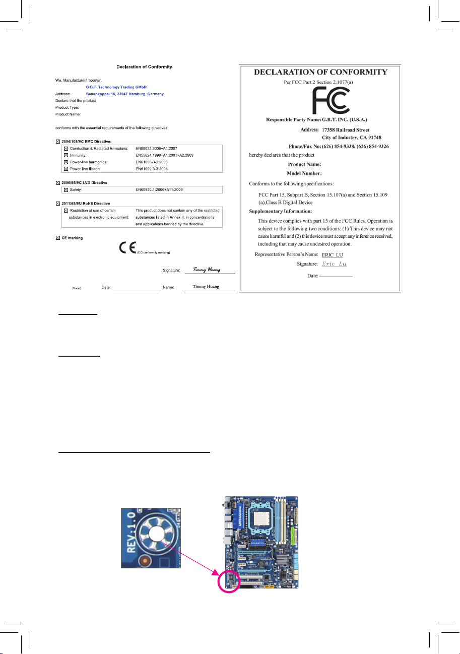
Identifying Your Motherboard Revision
The revision number on your motherboard looks like this: «REV: X.X.» For example, «REV: 1.0» means
the revision of the motherboard is 1.0. Check your motherboard revision before updating motherboard
BIOS, drivers, or when looking for technical information.
Example:

Table of Contents
GA-970A-DS3P Motherboard Layout ……………………………………………………………………4
GA-970A-DS3P Motherboard Block Diagram ………………………………………………………..5
Chapter 1 Hardware Installation ………………………………………………………………………….6
1-1 Installation Precautions ………………………………………………………………………… 6
1-2 Product Specications ………………………………………………………………………….. 7
1-3 Installing the CPU ……………………………………………………………………………….. 9
1-4 Installing the Memory …………………………………………………………………………… 9
1-5 Installing an Expansion Card ………………………………………………………………. 10
1-6 Back Panel Connectors ………………………………………………………………………. 10
1-7 Internal Connectors ……………………………………………………………………………. 11
Chapter 2 BIOS Setup ……………………………………………………………………………………..16
2-1 Startup Screen ………………………………………………………………………………….. 16
2-2 M.I.T. ……………………………………………………………………………………………….. 17
2-3 System …………………………………………………………………………………………….. 21
2-4 BIOS Features ………………………………………………………………………………….. 22
2-5 Peripherals ……………………………………………………………………………………….. 24
2-6 Power Management …………………………………………………………………………… 26
2-7 Save & Exit ……………………………………………………………………………………….. 27
Chapter 3 Drivers Installation …………………………………………………………………………….28
Regulatory Statements …………………………………………………………………………………. 29
Contact Us …………………………………………………………………………………………………. 32
— 3 —
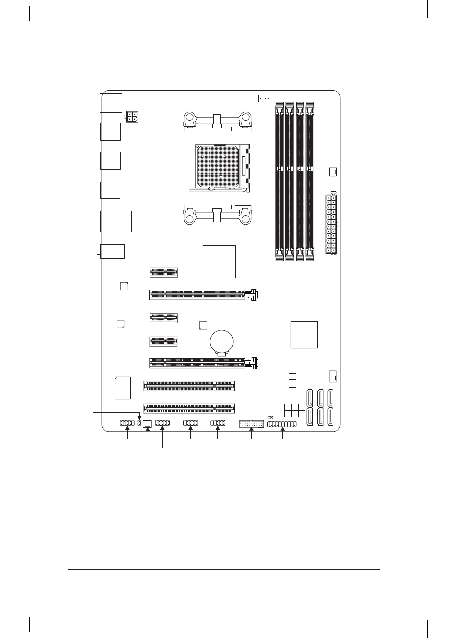
GA-970A-DS3P Motherboard Layout
SPDIF_O
KB_MS
R_USB2
R_USB1
R_USB30
USB_LAN
AUDIO
Realtek®
GbE LAN
CODEC
CPU_FAN
ATX_12V
Socket AM3+
PWR_FAN
DDR3_3
DDR3_1
SYS_FAN1
ATX
(Note)
PCIEX1_1
PCIEX16
PCIEX1_2
PCIEX1_3
PCIEX4
PCI1
®
iTE
Super
I/O
PCI2
AMD 970
GA-970A-DS3P
VIA®
VL805
BAT
M_BIOS
B_BIOS
CLR_CMOS
DDR3_4
DDR3_2
AMD SB950
SATA 3
0 2 4
1 3 5
F_AUDIO
SYS_FAN2
F_USB3
F_USB1
F_PANELF_USB30F_USB2
(Note) Due to a hardware limitation, the PCIEX1_1 slot can only accommodate a shorter PCI Express x1 expansion card.
For a longer expansion card, use other expansion slots.
Box Contents
5 GA-970A-DS3P motherboard
5 Motherboard driver disk 5 Two SATA cables
5 User’s Manual 5 I/O Shield
* The box contents above are for reference only and the actual items shall depend on the product package you obtain.
— 4 —
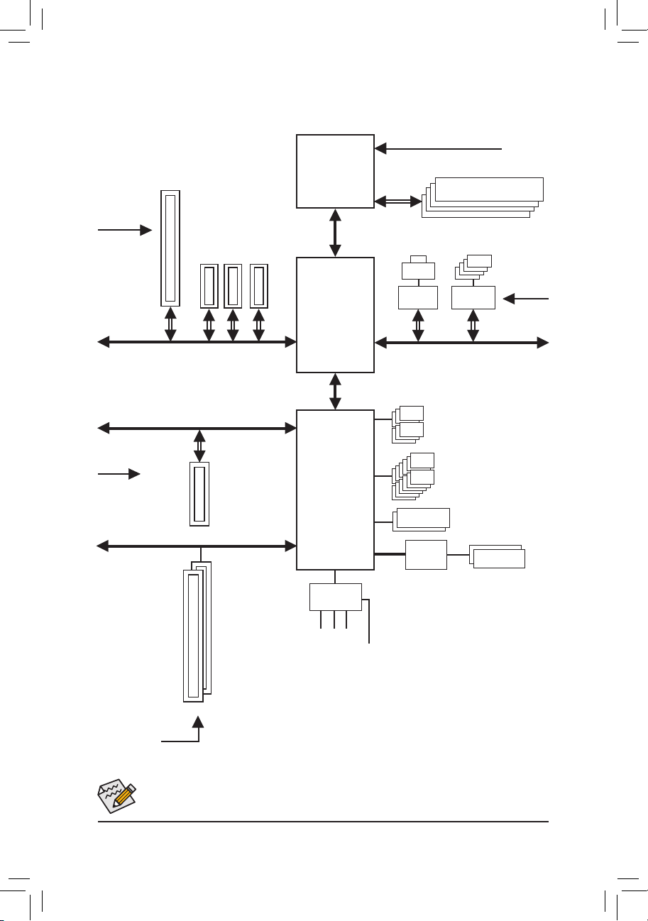
GA-970A-DS3P Motherboard Block Diagram
CPU CLK+/- (200 MHz)
DDR3 2000 (O.C.)/1866/1600/
1 PCI Express x16
AM3+/AM3 CPU
1333/1066 MHz
Dual Channel Memory
PCIe CLK
(100 MHz)
PCIe CLK
(100 MHz)
3 PCI Express x1
x16
x1 x1 x1
PCI Express Bus
PCI Express Bus
x4
1 PCI Express x4
PCI Bus
Hyper Transport Bus
AMD 970
AMD SB950
CODEC
LPC
Bus
LAN
RJ45
Realtek®
GbE LAN
x1
PCI Express Bus
6 SATA 6Gb/s
Dual BIOS
iTE®
Super I/O
4 USB 3.0/2.0
VIA® VL805
x1
12 USB 2.0/1.1
PS/2 KB/Mouse
PCIe CLK
(100 MHz)
S/PDIF Out
2 PCI
Line In (Rear Speaker Out)
PCI CLK
Line Out (Front Speaker Out)
(33 MHz)
MIC (Center/Subwoofer Speaker Out)
For detailed product information/limitation(s), refer to «1-2 Product Specications.»
— 5 —

Chapter 1 Hardware Installation
1-1 Installation Precautions
The motherboard contains numerous delicate electronic circuits and components which can become
damaged as a result of electrostatic discharge (ESD). Prior to installation, carefully read the user’s
manual and follow these procedures:
• Prior to installation, make sure the chassis is suitable for the motherboard.
• Prior to installation, do not remove or break motherboard S/N (Serial Number) sticker or
warranty sticker provided by your dealer. These stickers are required for warranty validation.
• Always remove the AC power by unplugging the power cord from the power outlet before
installing or removing the motherboard or other hardware components.
• When connecting hardware components to the internal connectors on the motherboard, make
sure they are connected tightly and securely.
• When handling the motherboard, avoid touching any metal leads or connectors.
• It is best to wear an electrostatic discharge (ESD) wrist strap when handling electronic
components such as a motherboard, CPU or memory. If you do not have an ESD wrist strap,
keep your hands dry and rst touch a metal object to eliminate static electricity.
• Prior to installing the motherboard, please have it on top of an antistatic pad or within an
electrostatic shielding container.
• Before unplugging the power supply cable from the motherboard, make sure the power supply
has been turned off.
• Before turning on the power, make sure the power supply voltage has been set according to
the local voltage standard.
• Before using the product, please verify that all cables and power connectors of your hardware
components are connected.
• To prevent damage to the motherboard, do not allow screws to come in contact with the
motherboard circuit or its components.
• Make sure there are no leftover screws or metal components placed on the motherboard or
within the computer casing.
• Do not place the computer system on an uneven surface.
• Do not place the computer system in a high-temperature environment.
• Turning on the computer power during the installation process can lead to damage to system
components as well as physical harm to the user.
• If you are uncertain about any installation steps or have a problem related to the use of the
product, please consult a certied computer technician.
— 6 —
1-2 ProductSpecications
CPU AM3+ Socket:
— AMD AM3+ FX processor
— AMD AM3 Phenom™ II processor/ AMD Athlon™ II processor
(Go to GIGABYTE’s website for the latest CPU support list.)
Hyper Transport
Bus
Chipset
Memory 4 x 1.5V DDR3 DIMM sockets supporting up to 32 GB of system memory
Audio Realtek® ALC887 audio codec
LAN Realtek® GbE LAN chip (10/100/1000 Mbit)
Expansion Slots 1 x PCI Express x16 slot, running at x16 (PCIEX16)
Storage Interface South Bridge:
USB South Bridge:
Internal
Connectors
4800 MT/s
North Bridge: AMD 970
South Bridge: AMD SB950
* Due to a Windows 32-bit operating system limitation, when more than 4 GB of physical
memory is installed, the actual memory size displayed will be less than the size of
the physical memory installed.
Dual channel memory architecture
Support for DDR3 2000(O.C.)/1866/1600/1333/1066 MHz memory modules
* To support a DDR3 1866 MHz (and above) memory, you must install an AM3+ CPU rst.
(Go to GIGABYTE’s website for the latest supported memory speeds and memory
modules.)
High Denition Audio
2/4/5.1/7.1-channel
Support for S/PDIF Out
* For optimum performance, if only one PCI Express graphics card is to be installed,
be sure to install it in the PCIEX16 slot.
1 x PCI Express x16 slot, running at x4 (PCIEX4)
3 x PCI Express x1 slots
(All PCI Express slots conform to PCI Express 2.0 standard.)
2 x PCI slots
— 6 x SATA 6Gb/s connectors supporting up to 6 SATA 6Gb/s devices
— Support for RAID 0, RAID 1, RAID 5, RAID 10, and JBOD
— Up to 12 USB 2.0/1.1 ports (6 ports on the back panel, 6 ports available
through the internal USB headers)
VIA® VL805 chip:
— Up to 4 USB 3.0/2.0 ports (2 ports on the back panel, 2 ports available through
the internal USB header)
1 x 24-pin ATX main power connector
1 x 4-pin ATX 12V power connector
6 x SATA 6Gb/s connectors
1 x CPU fan header
2 x system fan headers
1 x power fan header
1 x front panel header
— 7 —
Internal
Connectors
1 x front panel audio header
1 x S/PDIF Out header
1 x USB 3.0/2.0 header
3 x USB 2.0/1.1 headers
1 x Clear CMOS jumper
Back Panel
Connectors
1 x PS/2 keyboard port
1 x PS/2 mouse port
2 x USB 3.0/2.0 ports
6 x USB 2.0/1.1 ports
1 x RJ-45 port
3 x audio jacks (Line In/Line Out/Microphone)
I/O Controller iTE® I/O Controller Chip
Hardware
Monitor
System voltage detection
CPU/System temperature detection
CPU/System/Power fan speed detection
CPU overheating warning
CPU/System/Power fan fail warning
CPU/System fan speed control
* Whether the CPU/system fan speed control function is supported will depend on the
CPU/system cooler you install.
BIOS 2 x 32 Mbit ash
Use of licensed AMI EFI BIOS
Support for DualBIOS
™
PnP 1.0a, DMI 2.0, SM BIOS 2.6, ACPI 2.0a
Unique Features Support for @BIOS
Support for Q-Flash
Support for Xpress Install
Support for EasyTune
* Available functions in EasyTune may differ by motherboard model.
Support for Smart Recovery 2
Support for Auto Green
Support for ON/OFF Charge
Support for 3TB+ Unlock
Support for Q-Share
Bundled
Software
Operating
System
Norton Internet Security (OEM version)
Support for Windows 8/7/XP
Form Factor ATX Form Factor; 30.5cm x 21.5cm
* GIGABYTE reserves the right to make any changes to the product specications and product-related information without
prior notice.
* Please visit the Support & Downloads\Utility page on GIGABYTE’s website to check the supported operating system(s)
for the software listed in the «Unique Features» and «Bundled Software» columns.
— 8 —
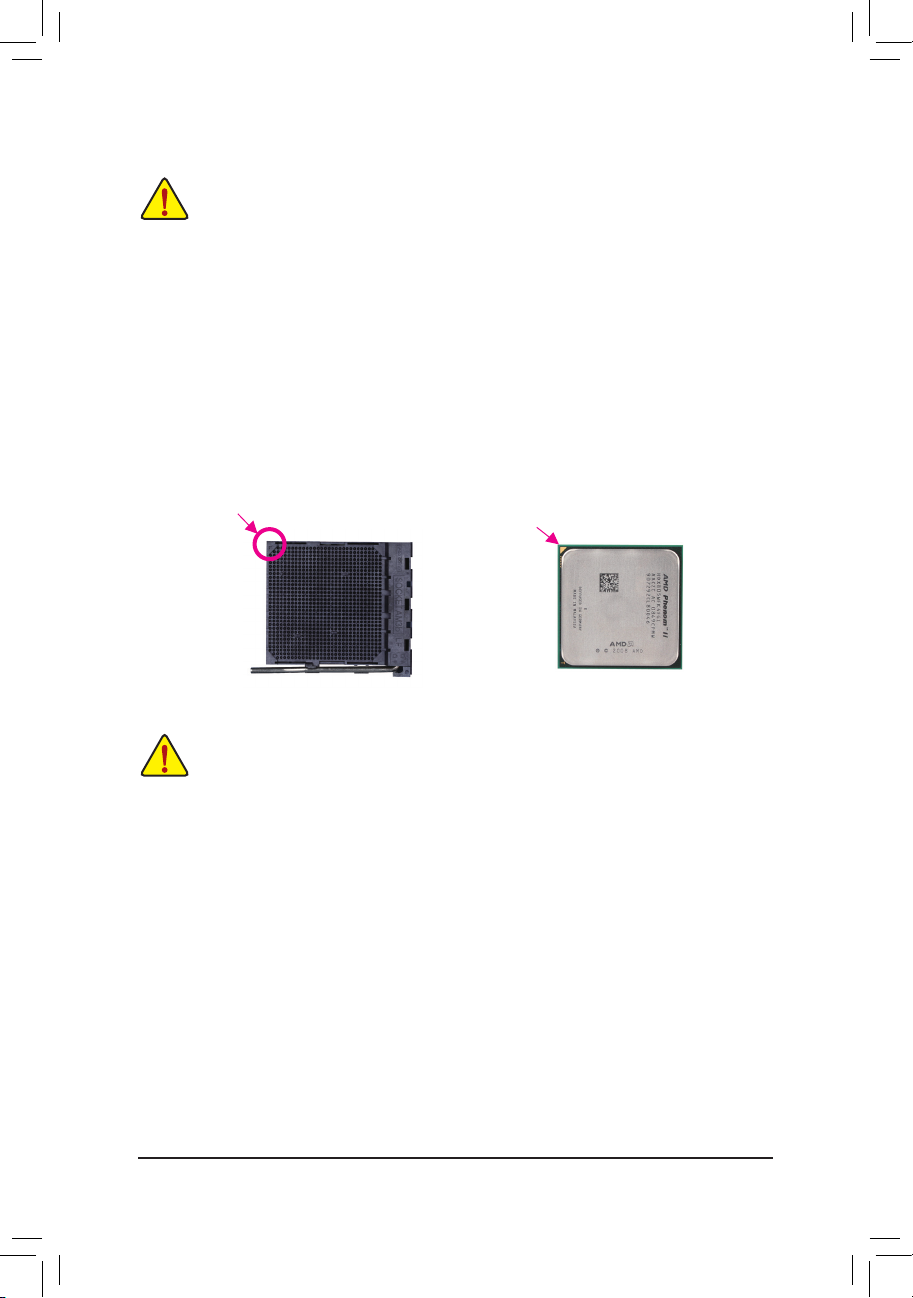
1-3 Installing the CPU
Read the following guidelines before you begin to install the CPU:
• Make sure that the motherboard supports the CPU.
(Go to GIGABYTE’s website for the latest CPU support list.)
• Always turn off the computer and unplug the power cord from the power outlet before installing the CPU
to prevent hardware damage.
• Locate the pin one of the CPU. The CPU cannot be inserted if oriented incorrectly. (Or you may locate
the notches on both sides of the CPU and alignment keys on the CPU socket.)
• Apply an even and thin layer of thermal grease on the surface of the CPU.
• Do not turn on the computer if the CPU cooler is not installed, otherwise overheating and damage of
the CPU may occur.
• Set the CPU host frequency in accordance with the CPU specications. It is not recommended that
the system bus frequency be set beyond hardware specications since it does not meet the standard
requirements for the peripherals. If you wish to set the frequency beyond the standard specications, please
do so according to your hardware specications including the CPU, graphics card, memory, hard drive, etc.
Installing the CPU
Locate the pin one (denoted by a small triangle) of the CPU socket and the CPU.
A Small Triangle
Marking Denotes Pin
One of the Socket
AM3+ Socket
A Small Triangle
Marking Denotes
CPU Pin One
AM3+/AM3 CPU
1-4 Installing the Memory
Read the following guidelines before you begin to install the memory:
• Make sure that the motherboard supports the memory. It is recommended that memory of the same
capacity, brand, speed, and chips be used.
(Go to GIGABYTE’s website for the latest supported memory speeds and memory modules.)
• Always turn off the computer and unplug the power cord from the power outlet before installing the memory
to prevent hardware damage.
• Memory modules have a foolproof design. A memory module can be installed in only one direction. If you
are unable to insert the memory, switch the direction.
DualChannelMemoryConguration
This motherboard provides four DDR3 memory sockets and supports Dual Channel Technology. After the memory is
installed, the BIOS will automatically detect the specications and capacity of the memory. Enabling Dual Channel
memory mode will double the original memory bandwidth.
The four DDR3 memory sockets are divided into two channels and each channel has two memory sockets as following:
Channel A: DDR3_2, DDR3_4
Channel B: DDR3_1, DDR3_3
Due to CPU limitations, read the following guidelines before installing the memory in Dual Channel mode.
1. Dual Channel mode cannot be enabled if only one DDR3 memory module is installed.
2. When enabling Dual Channel mode with two or four memory modules, it is recommended that memory of
the same capacity, brand, speed, and chips be used and installed in the same colored DDR3 sockets for
optimum performance. For optimum performance, when enabling Dual Channel mode with two memory
modules, we recommend that you install them in the DDR3_1 and DDR3_2 sockets.
— 9 —
1-5 Installing an Expansion Card
Read the following guidelines before you begin to install an expansion card:
• Make sure the motherboard supports the expansion card. Carefully read the manual that came
with your expansion card.
• Always turn off the computer and unplug the power cord from the power outlet before installing an
expansion card to prevent hardware damage.
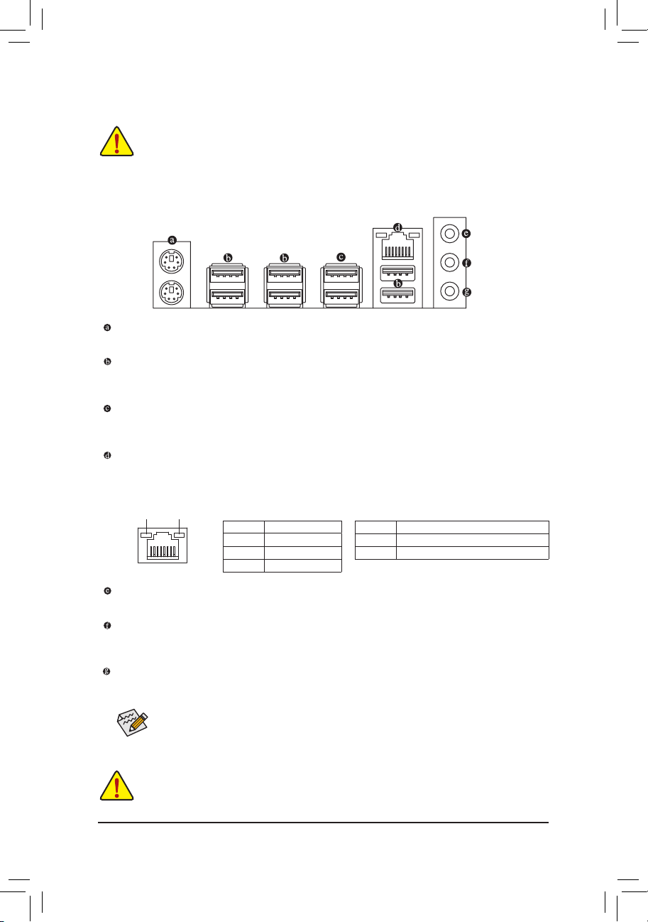
1-6 Back Panel Connectors
PS/2 Keyboard/Mouse Port
Use this port to connect a PS/2 mouse or keyboard.
USB 2.0/1.1 Port
The USB port supports the USB 2.0/1.1 specication. Use this port for USB devices such as a USB
keyboard/mouse, USB printer, USB ash drive and etc.
USB 3.0/2.0 Port
The USB 3.0 port supports the USB 3.0 specication and is compatible to the USB 2.0/1.1 specication.
Use this port for USB devices such as a USB keyboard/mouse, USB printer, USB ash drive and etc.
RJ-45 LAN Port
The Gigabit Ethernet LAN port provides Internet connection at up to 1 Gbps data rate. The following
describes the states of the LAN port LEDs.
Connection/
Speed LED
Line In Jack (Blue)
The default line in jack. Use this audio jack for line in devices such as an optical drive, walkman, etc.
Line Out Jack (Green)
The default line out jack. Use this audio jack for a headphone or 2-channel speaker. This jack can be used
to connect front speakers in a 4/5.1/7.1-channel audio conguration.
Mic In Jack (Pink)
The default Mic in jack. Microphones must be connected to this jack.
LAN Port
Activity LED
Connection/Speed LED:
State Description
Orange 1 Gbps data rate
Green 100 Mbps data rate
Off 10 Mbps data rate
Activity LED:
State Description
Blinking Data transmission or receiving is occurring
Off No data transmission or receiving is occurring
To congure 7.1-channel audio, you have to use an HD front panel audio module and enable the
multi-channel audio feature through the audio driver.
• When removing the cable connected to a back panel connector, rst remove the cable from your
device and then remove it from the motherboard.
• When removing the cable, pull it straight out from the connector. Do not rock it side to side to prevent
an electrical short inside the cable connector.
— 10 —
Loading…
Найди любой мануал:
Например: Sony VGN-FW460J/T
Вы можете бесплатно скачать Руководство по эксплуатации для GIGABYTE GA-970A-DS3P (rev. 1.0).
Также вы сможете прочесть онлайн этот документ без скачивания.
Скачать Руководство по эксплуатации для GIGABYTE GA-970A-DS3P (rev. 1.0)
Тип файла
PDF
Размер
10.15 Mb
Кол-во страниц
32
Просмотров
16911
Читать онлайн Руководство по эксплуатации для GIGABYTE GA-970A-DS3P (rev. 1.0) (Страница 1)

Другие Материнские платы GIGABYTE GA-970A-DS3P (rev. 1.0)
Топ GIGABYTE Материнские платы
Ранее вы смотрели
Эта страница полезна для вас? Поделитесь ссылкой:
-
Page 1
GA-970A-DS3P User’s Manual Rev. 1001 12ME-970AS3P-1001R… -
Page 2: Identifying Motherboard Revision
Information in this manual is protected by copyright laws and is the property of GIGABYTE. Changes to the specifications and features in this manual may be made by GIGABYTE without prior notice. No part of this manual may be reproduced, copied, translated, transmitted, or published in any form or by any means without GIGABYTE’s prior written permission.
-
Page 3: Table Of Contents
Table of Contents GA-970A-DS3P Motherboard Layout …………….4 GA-970A-DS3P Motherboard Block Diagram …………..5 Chapter 1 Hardware Installation ………………6 Installation Precautions ………………6 Product Specifications ………………7 Installing the CPU ……………….. 9 Installing the Memory ………………9 Installing an Expansion Card …………….. 10 Back Panel Connectors ………………
-
Page 4: Box Contents
GA-970A-DS3P Motherboard Layout CPU_FAN KB_MS ATX_12V R_USB2 Socket AM3+ R_USB1 PWR_FAN R_USB30 USB_LAN AUDIO AMD 970 PCIEX1_1 (Note) Realtek ® GbE LAN PCIEX16 GA-970A-DS3P PCIEX1_2 CODEC ® VL805 PCIEX1_3 AMD SB950 PCIEX4 M_BIOS SYS_FAN1 PCI1 B_BIOS PCI2 SATA3 0 2 4…
-
Page 5: Ga-970A-Ds3P Motherboard Block Diagram
GA-970A-DS3P Motherboard Block Diagram CPU CLK+/- (200 MHz) DDR3 2000 (O.C.)/1866/1600/ AM3+/AM3 CPU 1333/1066 MHz 1 PCI Express x16 Dual Channel Memory Hyper Transport Bus PCIe CLK 4 USB 3.0/2.0 (100 MHz) 3 PCI Express x1 RJ45 Realtek ® VL805 ®…
-
Page 6: Chapter 1 Hardware Installation
Chapter 1 Hardware Installation Installation Precautions The motherboard contains numerous delicate electronic circuits and components which can become damaged as a result of electrostatic discharge (ESD). Prior to installation, carefully read the user’s manual and follow these procedures: • Prior to installation, make sure the chassis is suitable for the motherboard. •…
-
Page 7: 1-2 Product Specifications
Support for DDR3 2000(O.C.)/1866/1600/1333/1066 MHz memory modules Š * To support a DDR3 1866 MHz (and above) memory, you must install an AM3+ CPU first. (Go to GIGABYTE’s website for the latest supported memory speeds and memory modules.) Audio Realtek ALC887 audio codec Š…
-
Page 8
ATX Form Factor; 30.5cm x 21.5cm Š * GIGABYTE reserves the right to make any changes to the product specifications and product-related information without prior notice. * Please visit the Support & DownloadsUtility page on GIGABYTE’s website to check the supported operating system(s) for the software listed in the «Unique Features»… -
Page 9: Installing The Cpu
• Make sure that the motherboard supports the memory. It is recommended that memory of the same capacity, brand, speed, and chips be used. (Go to GIGABYTE’s website for the latest supported memory speeds and memory modules.) • Always turn off the computer and unplug the power cord from the power outlet before installing the memory to prevent hardware damage.
-
Page 10: Installing An Expansion Card
Installing an Expansion Card Read the following guidelines before you begin to install an expansion card: • Make sure the motherboard supports the expansion card. Carefully read the manual that came with your expansion card. • Always turn off the computer and unplug the power cord from the power outlet before installing an expansion card to prevent hardware damage.
-
Page 11: Internal Connectors
Internal Connectors ATX_12V F_PANEL CPU_FAN F_AUDIO SYS_FAN1/SYS_FAN2 SPDIF_O PWR_FAN F_USB30 SATA3 0/1/2/3/4/5 F_USB1/F_USB2/F_USB3 CLR_CMOS Read the following guidelines before connecting external devices: • First make sure your devices are compliant with the connectors you wish to connect. • Before installing the devices, be sure to turn off the devices and your computer. Unplug the power cord from the power outlet to prevent damage to the devices.
-
Page 12: Cpu_Fan/Sys_Fan Fan Headers
1/2) ATX_12V/ATX (2×2 12V Power Connector and 2×12 Main Power Connector) With the use of the power connector, the power supply can supply enough stable power to all the components on the motherboard. Before connecting the power connector, first make sure the power supply is turned off and all devices are properly installed.
-
Page 13
6) SATA3 0/1/2/3/4/5 (SATA 6Gb/s Connectors) The SATA connectors conform to SATA 6Gb/s standard and are compatible with SATA 3Gb/s and SATA 1.5Gb/s standard. Each SATA connector supports a single SATA device. The AMD SB950 controller supports RAID 0, RAID 1, RAID 5, RAID 10, and JBOD. Pin No. -
Page 14: Front Panel Header
9) F_PANEL (Front Panel Header) Connect the power switch, reset switch, speaker, chassis intrusion switch/sensor and system status indicator on the chassis to this header according to the pin assignments below. Note the positive and negative pins before connecting the cables. •…
-
Page 15
11) SPDIF_O (S/PDIF Out Header) This header supports digital S/PDIF Out and connects a S/PDIF digital audio cable (provided by expansion cards) for digital audio output from your motherboard to certain expansion cards like graphics cards and sound cards. For example, some graphics cards may require you to use a S/PDIF digital audio cable for digital audio output from your motherboard to your graphics card if you wish to connect an HDMI display 1 2 3 to the graphics card and have digital audio output from the HDMI display at the same time. -
Page 16: Chapter 2 Bios Setup
To access the BIOS Setup program, press the <Delete> key during the POST when the power is turned on. To upgrade the BIOS, use either the GIGABYTE Q-Flash or @BIOS utility. Q-Flash allows the user to quickly and easily upgrade or back up BIOS without entering the operating system.
-
Page 17: M.i.t
M.I.T. This section provides information on the BIOS version, CPU base clock, CPU frequency, memory frequency, total memory size, CPU temperature, Vcore, and memory voltage. Whether the system will work stably with the overclock/overvoltage settings you made is dependent on your overall system configurations.
-
Page 18: C1E Support
& Core Performance Boost (Note 1) Allows you to determine whether to enable the Core Performance Boost (CPB) technology, a CPU performance-boost technology. (Default: Auto) & CPB Ratio (Note 1) Allows you alter the ratio for the CPB. The adjustable range is dependent on the CPU being installed. (Default: Auto) &…
-
Page 19
` Advanced Memory Settings & Extreme Memory Profile (X.M.P.) , System Memory Multiplier, Memory Frequency(MHz) (Note) The settings above are synchronous to those under the same items on the Advanced Frequency Settings menu. & DRAM Timing Selectable Quick and Expert allows the Channel Interleaving, Rank Interleaving, and memory timing settings below to be configurable. -
Page 20
& CPU/System/Power Fan Speed Displays current CPU/system/power fan speed. & CPU Warning Temperature Sets the warning threshold for CPU temperature. When CPU temperature exceeds the threshold, BIOS will emit warning sound. Options are: Disabled (default), 60 C/140 F, 70 C/158 F, 80 C/176 F, 90… -
Page 21: System
System This section provides information on your motherboard model and BIOS version. You can also select the default language used by the BIOS and manually set the system time. & System Language Selects the default language used by the BIOS. &…
-
Page 22: Bios Features
System (Default) & Full Screen LOGO Show Allows you to determine whether to display the GIGABYTE Logo at system startup. Disabled skips the GIGABYTE Logo when the system starts up. (Default: Enabled) & OS Type Allows you to select the operating system to be installed. Set this item to Windows 8 for Windows 8 operating system.
-
Page 23: Boot Mode Selection
& CSM Support Enables or disables UEFI CSM (Compatibility Support Module) to support a legacy PC boot process. Enables UEFI CSM. (Default) Always Disables UEFI CSM and supports UEFI BIOS boot process only. Never This item is configurable only when OS Type is set to Windows 8 or Windows 8 WHQL. &…
-
Page 24: Peripherals
Peripherals & OnChip SATA Controller Enables or disables the integrated SATA controllers. (Default: Enabled) & OnChip SATA Type Enables or disables RAID for the SATA controllers integrated in the AMD Chipset or configures the SATA controllers to AHCI mode. Native IDE Configures the SATA controller to IDE mode.
-
Page 25
& Legacy USB Support Allows USB keyboard/mouse to be used in MS-DOS. (Default: Enabled) & XHCI Hand-off Determines whether to enable XHCI Hand-off feature for an operating system without XHCI Hand-off support. (Default: Enabled) & EHCI Hand-off Determines whether to enable EHCI Hand-off feature for an operating system without EHCI Hand-off support. -
Page 26: Power Management
Power Management & Resume by Alarm Determines whether to power on the system at a desired time. (Default: Disabled) If enabled, set the date and time as following: Wake up day: Turn on the system at a specific time on each day or on a specific day in a month. Wake up hour/minute/second: Set the time at which the system will be powered on automatically.
-
Page 27: Save & Exit
& Power On Password Set the password when Power On By Keyboard is set to Password. Press <Enter> on this item and set a password with up to 5 characters and then press <Enter> to accept. To turn on the system, enter the password and press <Enter>. Note: To cancel the password, press <Enter>…
-
Page 28: Chapter 3 Drivers Installation
& Boot Override Allows you to select a device to boot immediately. Press <Enter> on the device you select and select Yes to confirm. Your system will restart automatically and boot from that device. & Save Profiles This function allows you to save the current BIOS settings to a profile. You can create up to 8 profiles and save as Setup Profile 1~ Setup Profile 8.
-
Page 29: Regulatory Statements
Contravention will be prosecuted. We believe that the information contained herein was accurate in all respects at the time of printing. GIGABYTE cannot, however, assume any responsibility for errors or omissions in this text. Also note that the information in this document is subject to change without notice and should not be construed as a commitment by GIGABYTE.
-
Page 30
— 30 -… -
Page 31
— 31 -… -
Page 32: Contact Us
Tech. and Non-Tech. Support (Sales/Marketing) : http://ggts.gigabyte.com.tw WEB address (English): http://www.gigabyte.com WEB address (Chinese): http://www.gigabyte.tw You may go to the GIGABYTE website, select your language in the language list on the top right corner of the website. GIGABYTE Global Service System •…