
DA-53T
Reference Manual
Operation of Version 1.5
English
Preface
This manual describes the operation of the Delem control type DA-53T and is meant for operators who are instructed for operation of the total machine.
Delem Limited warranty
• This manual does not entitle you to any rights. Delem reserves the right to change this
manual without prior warning.
• All rights reserved. The copyright is held by Delem. No part of this publication may be
copied or reproduced without written permission from Delem BV.
Version history
The control software is updated regularly to increase performance and add new functionality.
This manual is also updated as a result of changes in the control software. The following over-
view shows the relation between software and manual versions.
| Software version | Manual version | Description |
| V1.5 | V0817 | first issue V1 |
This manual is valid for software version 1.5 and higher.
Table of contents
1. Operation overview and general introduction . . . . . . . . . . . . . . . . . . . . 1.1
1.1. The control unit . . . . . . . . . . . . . . . . . . . . . . . . . . . . . . . . . . . . . . . . . . . . . . . . . . . . 1.1
1.2. Front control elements . . . . . . . . . . . . . . . . . . . . . . . . . . . . . . . . . . . . . . . . . . . . . . 1.2
1.3. USB connectors . . . . . . . . . . . . . . . . . . . . . . . . . . . . . . . . . . . . . . . . . . . . . . . . . . . 1.3
1.4. Operation and programming modes . . . . . . . . . . . . . . . . . . . . . . . . . . . . . . . . . . . . 1.4
1.5. Getting started . . . . . . . . . . . . . . . . . . . . . . . . . . . . . . . . . . . . . . . . . . . . . . . . . . . . 1.7
1.5.1. Introduction . . . . . . . . . . . . . . . . . . . . . . . . . . . . . . . . . . . . . . . . . . . . . . . . . . . 1.7
1.5.2. Preparations . . . . . . . . . . . . . . . . . . . . . . . . . . . . . . . . . . . . . . . . . . . . . . . . . . 1.7
1.5.3. Modifying a program . . . . . . . . . . . . . . . . . . . . . . . . . . . . . . . . . . . . . . . . . . . . 1.7
1.5.4. The Auto menu and Manual menu, production modes . . . . . . . . . . . . . . . . . . 1.7
1.5.5. Back-up data, external storage . . . . . . . . . . . . . . . . . . . . . . . . . . . . . . . . . . . . 1.8
1.6. Programming aids . . . . . . . . . . . . . . . . . . . . . . . . . . . . . . . . . . . . . . . . . . . . . . . . . . 1.9
1.6.1. Listbox functionality . . . . . . . . . . . . . . . . . . . . . . . . . . . . . . . . . . . . . . . . . . . . 1.9
1.6.2. Parameter zoom functionality . . . . . . . . . . . . . . . . . . . . . . . . . . . . . . . . . . . . 1.10
1.6.3. Navigation . . . . . . . . . . . . . . . . . . . . . . . . . . . . . . . . . . . . . . . . . . . . . . . . . . . 1.11
1.6.4. Text input and editing . . . . . . . . . . . . . . . . . . . . . . . . . . . . . . . . . . . . . . . . . . 1.11
1.6.5. Typing alphanumeric characters vs. special characters . . . . . . . . . . . . . . . . 1.12
1.6.6. Messages centre . . . . . . . . . . . . . . . . . . . . . . . . . . . . . . . . . . . . . . . . . . . . . 1.13
1.6.7. Key-lock function . . . . . . . . . . . . . . . . . . . . . . . . . . . . . . . . . . . . . . . . . . . . . . 1.13
1.6.8. Manual positioning . . . . . . . . . . . . . . . . . . . . . . . . . . . . . . . . . . . . . . . . . . . . 1.15
1.6.9. Software versions . . . . . . . . . . . . . . . . . . . . . . . . . . . . . . . . . . . . . . . . . . . . . 1.16
2. Products, the product library . . . . . . . . . . . . . . . . . . . . . . . . . . . . . . . . . . 2.1
2.1. Introduction . . . . . . . . . . . . . . . . . . . . . . . . . . . . . . . . . . . . . . . . . . . . . . . . . . . . . . . 2.1
2.1.1. The main view . . . . . . . . . . . . . . . . . . . . . . . . . . . . . . . . . . . . . . . . . . . . . . . . 2.1
2.1.2. Product selection . . . . . . . . . . . . . . . . . . . . . . . . . . . . . . . . . . . . . . . . . . . . . . 2.2
2.1.3. New Program, starting a numerical program . . . . . . . . . . . . . . . . . . . . . . . . . 2.3
2.1.4. Edit, Copying and Deleting a product or program . . . . . . . . . . . . . . . . . . . . . 2.4
2.1.5. Product Rename . . . . . . . . . . . . . . . . . . . . . . . . . . . . . . . . . . . . . . . . . . . . . . . 2.5
3. Tool configuration . . . . . . . . . . . . . . . . . . . . . . . . . . . . . . . . . . . . . . . . . . 3.1
3.1. Introduction . . . . . . . . . . . . . . . . . . . . . . . . . . . . . . . . . . . . . . . . . . . . . . . . . . . . . . . 3.1
3.2. Standard procedure . . . . . . . . . . . . . . . . . . . . . . . . . . . . . . . . . . . . . . . . . . . . . . . . 3.1
3.3. Tool selection . . . . . . . . . . . . . . . . . . . . . . . . . . . . . . . . . . . . . . . . . . . . . . . . . . . . . 3.2
4. Product programming . . . . . . . . . . . . . . . . . . . . . . . . . . . . . . . . . . . . . . . 4.1
4.1. Introduction . . . . . . . . . . . . . . . . . . . . . . . . . . . . . . . . . . . . . . . . . . . . . . . . . . . . . . . 4.1
4.2. Program mode, parameter explanation . . . . . . . . . . . . . . . . . . . . . . . . . . . . . . . . . 4.3
4.2.1. Bend parameters . . . . . . . . . . . . . . . . . . . . . . . . . . . . . . . . . . . . . . . . . . . . . . 4.3
4.2.2. Force . . . . . . . . . . . . . . . . . . . . . . . . . . . . . . . . . . . . . . . . . . . . . . . . . . . . . . . 4.5
4.2.3. Speed . . . . . . . . . . . . . . . . . . . . . . . . . . . . . . . . . . . . . . . . . . . . . . . . . . . . . . . 4.6
4.2.4. Functions . . . . . . . . . . . . . . . . . . . . . . . . . . . . . . . . . . . . . . . . . . . . . . . . . . . . 4.6
4.2.5. Product properties . . . . . . . . . . . . . . . . . . . . . . . . . . . . . . . . . . . . . . . . . . . . . 4.7
4.2.6. Tools . . . . . . . . . . . . . . . . . . . . . . . . . . . . . . . . . . . . . . . . . . . . . . . . . . . . . . . . 4.7
4.2.7. Auxiliary axes . . . . . . . . . . . . . . . . . . . . . . . . . . . . . . . . . . . . . . . . . . . . . . . . . 4.7
4.3. Edit / view modes . . . . . . . . . . . . . . . . . . . . . . . . . . . . . . . . . . . . . . . . . . . . . . . . . . 4.8
4.3.1. All Bends . . . . . . . . . . . . . . . . . . . . . . . . . . . . . . . . . . . . . . . . . . . . . . . . . . . . 4.8
4.3.2. Change tools . . . . . . . . . . . . . . . . . . . . . . . . . . . . . . . . . . . . . . . . . . . . . . . . 4.10
4.3.3. Product properties . . . . . . . . . . . . . . . . . . . . . . . . . . . . . . . . . . . . . . . . . . . . 4.11
4.3.4. Add bend . . . . . . . . . . . . . . . . . . . . . . . . . . . . . . . . . . . . . . . . . . . . . . . . . . . 4.14
4.3.5. Bumping . . . . . . . . . . . . . . . . . . . . . . . . . . . . . . . . . . . . . . . . . . . . . . . . . . . . 4.15
4.4. Programming parameters . . . . . . . . . . . . . . . . . . . . . . . . . . . . . . . . . . . . . . . . . . . 4.17
5. Automatic mode . . . . . . . . . . . . . . . . . . . . . . . . . . . . . . . . . . . . . . . . . . . . 5.1
5.1. Introduction . . . . . . . . . . . . . . . . . . . . . . . . . . . . . . . . . . . . . . . . . . . . . . . . . . . . . . . 5.1
5.1.1. Auto mode, parameter explanation . . . . . . . . . . . . . . . . . . . . . . . . . . . . . . . . . 5.2
Corrections . . . . . . . . . . . . . . . . . . . . . . . . . . . . . . . . . . . . . . . . . . . . . . . . . . . . . 5.2
General corrections . . . . . . . . . . . . . . . . . . . . . . . . . . . . . . . . . . . . . . . . . . . . . . 5.3
General . . . . . . . . . . . . . . . . . . . . . . . . . . . . . . . . . . . . . . . . . . . . . . . . . . . . . . . . 5.3
5.2. View modes . . . . . . . . . . . . . . . . . . . . . . . . . . . . . . . . . . . . . . . . . . . . . . . . . . . . . . 5.4
5.2.1. Main . . . . . . . . . . . . . . . . . . . . . . . . . . . . . . . . . . . . . . . . . . . . . . . . . . . . . . . . 5.5
Bend selector . . . . . . . . . . . . . . . . . . . . . . . . . . . . . . . . . . . . . . . . . . . . . . . . . . . 5.5
5.2.2. All bends . . . . . . . . . . . . . . . . . . . . . . . . . . . . . . . . . . . . . . . . . . . . . . . . . . . . . 5.6
5.2.3. Macro . . . . . . . . . . . . . . . . . . . . . . . . . . . . . . . . . . . . . . . . . . . . . . . . . . . . . . . 5.7
5.2.4. Manual positioning . . . . . . . . . . . . . . . . . . . . . . . . . . . . . . . . . . . . . . . . . . . . . 5.8
5.2.5. Corrections . . . . . . . . . . . . . . . . . . . . . . . . . . . . . . . . . . . . . . . . . . . . . . . . . . . 5.9
Calculate corrections, programming of measured angles . . . . . . . . . . . . . . . . 5.10
5.2.6. Diagnostics . . . . . . . . . . . . . . . . . . . . . . . . . . . . . . . . . . . . . . . . . . . . . . . . . . 5.11
5.3. Bumping correction . . . . . . . . . . . . . . . . . . . . . . . . . . . . . . . . . . . . . . . . . . . . . . . . 5.12
6. Manual mode . . . . . . . . . . . . . . . . . . . . . . . . . . . . . . . . . . . . . . . . . . . . . . . 6.1
6.1. Introduction . . . . . . . . . . . . . . . . . . . . . . . . . . . . . . . . . . . . . . . . . . . . . . . . . . . . . . . 6.1
6.1.1. Manual mode, parameter explanation . . . . . . . . . . . . . . . . . . . . . . . . . . . . . . 6.2
Bend parameters . . . . . . . . . . . . . . . . . . . . . . . . . . . . . . . . . . . . . . . . . . . . . . . . 6.2
Force . . . . . . . . . . . . . . . . . . . . . . . . . . . . . . . . . . . . . . . . . . . . . . . . . . . . . . . . . 6.4
Speed . . . . . . . . . . . . . . . . . . . . . . . . . . . . . . . . . . . . . . . . . . . . . . . . . . . . . . . . . 6.4
Functions . . . . . . . . . . . . . . . . . . . . . . . . . . . . . . . . . . . . . . . . . . . . . . . . . . . . . . 6.4
Product properties . . . . . . . . . . . . . . . . . . . . . . . . . . . . . . . . . . . . . . . . . . . . . . . 6.4
Tools . . . . . . . . . . . . . . . . . . . . . . . . . . . . . . . . . . . . . . . . . . . . . . . . . . . . . . . . . . 6.5
Auxiliary axes . . . . . . . . . . . . . . . . . . . . . . . . . . . . . . . . . . . . . . . . . . . . . . . . . . . 6.5
6.1.2. Tool setup . . . . . . . . . . . . . . . . . . . . . . . . . . . . . . . . . . . . . . . . . . . . . . . . . . . . 6.6
6.2. Programming parameters & Views . . . . . . . . . . . . . . . . . . . . . . . . . . . . . . . . . . . . . 6.7
View . . . . . . . . . . . . . . . . . . . . . . . . . . . . . . . . . . . . . . . . . . . . . . . . . . . . . . . . . . 6.7
6.3. Macro . . . . . . . . . . . . . . . . . . . . . . . . . . . . . . . . . . . . . . . . . . . . . . . . . . . . . . . . . . . 6.9
6.4. Manual movement of the axes . . . . . . . . . . . . . . . . . . . . . . . . . . . . . . . . . . . . . . . 6.10
6.4.1. Movement procedure . . . . . . . . . . . . . . . . . . . . . . . . . . . . . . . . . . . . . . . . . . 6.10
6.4.2. Teach . . . . . . . . . . . . . . . . . . . . . . . . . . . . . . . . . . . . . . . . . . . . . . . . . . . . . . 6.11
6.5. Corrections . . . . . . . . . . . . . . . . . . . . . . . . . . . . . . . . . . . . . . . . . . . . . . . . . . . . . . 6.12
6.6. Diagnostics . . . . . . . . . . . . . . . . . . . . . . . . . . . . . . . . . . . . . . . . . . . . . . . . . . . . . . 6.13
6.6.1. IO status . . . . . . . . . . . . . . . . . . . . . . . . . . . . . . . . . . . . . . . . . . . . . . . . . . . . 6.14
Zoomed IO . . . . . . . . . . . . . . . . . . . . . . . . . . . . . . . . . . . . . . . . . . . . . . . . . . . . 6.15
7. Settings . . . . . . . . . . . . . . . . . . . . . . . . . . . . . . . . . . . . . . . . . . . . . . . . . . . 7.1
7.1. Introduction . . . . . . . . . . . . . . . . . . . . . . . . . . . . . . . . . . . . . . . . . . . . . . . . . . . . . . . 7.1
7.2. General . . . . . . . . . . . . . . . . . . . . . . . . . . . . . . . . . . . . . . . . . . . . . . . . . . . . . . . . . . 7.2
7.3. Materials . . . . . . . . . . . . . . . . . . . . . . . . . . . . . . . . . . . . . . . . . . . . . . . . . . . . . . . . . 7.4
7.4. Backup / restore . . . . . . . . . . . . . . . . . . . . . . . . . . . . . . . . . . . . . . . . . . . . . . . . . . . 7.7
7.4.1. Product backup . . . . . . . . . . . . . . . . . . . . . . . . . . . . . . . . . . . . . . . . . . . . . . . . 7.8
7.4.2. Product restore . . . . . . . . . . . . . . . . . . . . . . . . . . . . . . . . . . . . . . . . . . . . . . . 7.10
7.4.3. Tool backup . . . . . . . . . . . . . . . . . . . . . . . . . . . . . . . . . . . . . . . . . . . . . . . . . 7.12
7.4.4. Tool restore . . . . . . . . . . . . . . . . . . . . . . . . . . . . . . . . . . . . . . . . . . . . . . . . . . 7.13
7.4.5. Backup and restore for Tables and Settings . . . . . . . . . . . . . . . . . . . . . . . . . 7.13
7.4.6. Directory navigation . . . . . . . . . . . . . . . . . . . . . . . . . . . . . . . . . . . . . . . . . . . 7.14
7.5. Program settings . . . . . . . . . . . . . . . . . . . . . . . . . . . . . . . . . . . . . . . . . . . . . . . . . . 7.15
7.6. Default values . . . . . . . . . . . . . . . . . . . . . . . . . . . . . . . . . . . . . . . . . . . . . . . . . . . . 7.18
7.7. Computation settings . . . . . . . . . . . . . . . . . . . . . . . . . . . . . . . . . . . . . . . . . . . . . . 7.20
7.8. Production settings . . . . . . . . . . . . . . . . . . . . . . . . . . . . . . . . . . . . . . . . . . . . . . . . 7.22
7.9. Time settings . . . . . . . . . . . . . . . . . . . . . . . . . . . . . . . . . . . . . . . . . . . . . . . . . . . . . 7.25
8. Machine . . . . . . . . . . . . . . . . . . . . . . . . . . . . . . . . . . . . . . . . . . . . . . . . . . . 8.1
8.1. Introduction . . . . . . . . . . . . . . . . . . . . . . . . . . . . . . . . . . . . . . . . . . . . . . . . . . . . . . . 8.1
8.2. Programming of Punches . . . . . . . . . . . . . . . . . . . . . . . . . . . . . . . . . . . . . . . . . . . . 8.2
8.2.1. Create a new punch . . . . . . . . . . . . . . . . . . . . . . . . . . . . . . . . . . . . . . . . . . . . 8.3
8.2.2. Standard punch . . . . . . . . . . . . . . . . . . . . . . . . . . . . . . . . . . . . . . . . . . . . . . . 8.4
8.2.3. Hem bend punch . . . . . . . . . . . . . . . . . . . . . . . . . . . . . . . . . . . . . . . . . . . . . . 8.7
8.2.4. Air + hem bend punch . . . . . . . . . . . . . . . . . . . . . . . . . . . . . . . . . . . . . . . . . . 8.8
8.2.5. Big radius punch . . . . . . . . . . . . . . . . . . . . . . . . . . . . . . . . . . . . . . . . . . . . . . 8.10
8.3. Programming of bottom dies . . . . . . . . . . . . . . . . . . . . . . . . . . . . . . . . . . . . . . . . . 8.11
8.3.1. Create a new die . . . . . . . . . . . . . . . . . . . . . . . . . . . . . . . . . . . . . . . . . . . . . 8.12
8.3.2. Standard die . . . . . . . . . . . . . . . . . . . . . . . . . . . . . . . . . . . . . . . . . . . . . . . . . 8.13
8.3.3. Hem bend die . . . . . . . . . . . . . . . . . . . . . . . . . . . . . . . . . . . . . . . . . . . . . . . . 8.16
8.3.4. Inside hem bend die . . . . . . . . . . . . . . . . . . . . . . . . . . . . . . . . . . . . . . . . . . . 8.17
8.3.5. Air + hem bend U die . . . . . . . . . . . . . . . . . . . . . . . . . . . . . . . . . . . . . . . . . . 8.20
8.4. Backgauge . . . . . . . . . . . . . . . . . . . . . . . . . . . . . . . . . . . . . . . . . . . . . . . . . . . . . . 8.21
8.5. Position corrections . . . . . . . . . . . . . . . . . . . . . . . . . . . . . . . . . . . . . . . . . . . . . . . 8.24
8.6. Maintenance . . . . . . . . . . . . . . . . . . . . . . . . . . . . . . . . . . . . . . . . . . . . . . . . . . . . . 8.25
8.7. System information . . . . . . . . . . . . . . . . . . . . . . . . . . . . . . . . . . . . . . . . . . . . . . . . 8.26
A. Parameter index . . . . . . . . . . . . . . . . . . . . . . . . . . . . . . . . . . . . . . . . . . . . A.1
1. Operation overview and general introduction
1.1. The control unit
The control looks as follows:

The precise appearance of your control may differ.
Operation of the control is mainly done over the touchscreen. A description of the functions
and available touch controls is given in the next sections of this manual, aside of the
description of the specific functions.
1.2. Front control elements
The Start and Stop button, integrated in the touch screen user interface:
Stop button + Start button
1.3. USB connectors
At the right side of the control a USB port is available for
connection of external devices, such as a memory stick
or an external keyboard or mouse.
1.4. Operation and programming modes
The control’s main screen looks as follows:

Depending on the navigation button which is active, the screen will differ. The above main
screen will appear having the Products function active.
Just by tapping the various modes, the specific mode will be selected.
The structure of the main screen is as follows:
Title panel
In the top the title panel is always shown. In this area you can find logo information, which
product is loaded and (when activated) the service row. Also machine indicators can be found
here.

Information panel
In the information panel all functions and visualisation related to the selected modes are
displayed and can be found.

Command panel
The command panel is part of the Information panel and is the location where the controls
related to the Information panel can be found.
Navigation panel
The Navigation panel is the area where all the major modes can be found. This area is always
visible. The controls, large buttons with icons, can be used to directly switch from one mode to
the other.

Explanation of the main modes / navigation buttons
To make a new program and select a program out of the product
library.
To setup the machine and modify existing tool setups.
To create a new CNC-program or edit an existing CNC- program
numerically.
To start production of the selected program.
To program all settings for making one single bend, not related to a program.
User settings and preferences applicable to the programming of
new programs. Also the required material properties can be
programmed in the Material library.
User settings and preferences applicable to the machine, tooling
library including the tool editor, backup/restore of data, software
version info etc.
1.5. Getting started
1.5.1. Introduction
In order to obtain a bend program for a product, the control offers the possibility to create a
program bend by bend and adjust specific parameters for each bend independently.
This is done with the following steps:
1 Go to the Products mode in the navigation panel and start a new program by tap-
ping New Program.
2 Enter the program’s basic properties and continue by pressing Accept.
3 Automatically the next menu is switched to, Tool-setup, to select the desired tool-
ing. Check the tooling, modify upon desire and one can continue to the Program
menu.
4 In the Program menu one can start programming the bend specific parameters for
the first bend. To add the next bendstep to the program the function Add bend can
be used. This cycle can be repeated upon choice.
5 Tap Auto and press the Start button in order to produce the programmed product.
1.5.2. Preparations
Before product programming can be started, the following preparations must be made.
• The correct material properties must have been programmed in the Materials library.
You can find this on the Materials page in the Settings mode.
• The correct tools must be programmed in the Tool Library. Tools are necessary to
create a CNC program. You can find the libraries for the different types of tools in the
Machine mode.
1.5.3. Modifying a program
The Program menu gives access to the numerical program and values of the active product.
Existing programs can be modified via this menu. The independent bendsteps can be
selected and the programmed values can be monitored and modified if required.
Axes positions, if applicable, are calculated according to the machine configuration.
1.5.4. The Auto menu and Manual menu, production modes
A product program can be executed via the Auto mode. In Automatic mode, a complete
program can be executed bend after bend. In the Auto mode the Step mode can be selected
to have each bend started separately.
The Manual mode of the control is an independent production mode. In this mode, one bend
can be programmed and executed. It is typically used to test the behaviour of the bend
system.
More information about this can be found in chapters 5 and 6.
1.5.5. Back-up data, external storage
Both product and tool files can be stored externally. These files can be stored on a USB stick.
This facilitates a back-up of important data and the possibility to exchange files between
Delem controls.
More information about this can be found in chapter 7.
1.6. Programming aids
1.6.1. Listbox functionality
Several parameters on the control have a limited number of possible values. When selecting
such a parameter, by tapping the parameter line on the screen, the list of options will open up
near the position where you tapped the line, and the desired value can be selected.

To undo the selection and the opened listbox, tapping outside the box will make it close
without changing the selected parameter.
1.6.2. Parameter zoom functionality
To improve the focus on parameters, and to ease the use while programming, the parameter
zoom function will enlarge specific parameterlines when being programmed. When selecting
e.g. force in Program mode, the force lines will expand giving them better focus while fine
tuning.

When selecting any other parameterline, the previous selection will be reduced and zoomed
out again, as the newly selected parameterline will be zoomed in at.
1.6.3. Navigation
Within some modes, the program screens are divided into tabs.

The tabs can easily be selected by just tapping them. When a tab is not completely visible or
not visible at all, just by dragging the tab row horizontally, the desired tab can be “pulled” in
sight and be selected.
1.6.4. Text input and editing
The cursor can be used to enter a specific value or text within an existing input. Just tap at the
desired position to do so. The cursor will appear and input will be added there.
1.6.5. Typing alphanumeric characters vs. special characters
Both alphanumeric characters and special characters can be used throughout the control. A
full on-screen alphanumerical keyboard will pop up when required.
When editing a field which is pure numeric, the alphanumeric characters will be hidden. For
fields which enable to use alphanumerical strings, the keyboard is completely available.
Special characters as ? % – can be found using the special character button on the left-lower
side of the keyboard.

Special characters (like á, à, â, ã, ä, å, æ) are supported by the on screen keyboard by
keeping a character (like ‘a’) pressed.

1.6.6. Messages centre
When messages are displayed coming from PLC, Safety systems or the Sequencer, these
messages can be ‘send’ to the ‘Messages centre’. When a message is displayed
simultaneously the message centre symbol is shown in the top row of the page header, next
to e.g. the key lock symbol. When tapping this message centre symbol the messages are taken
from the screen, giving way for normal programming and editing. When tapping again the
actual messages are shown.
When messages are in the background, the message centre symbol has an extra indicator to
show new incoming messages which are not yet shown.

1.6.7. Key lock function
To prevent for changes to products or programs, the key lock function offers the possibility to
lock the control.
There are two levels of locking the control. Program Lock and Machine Lock.
• In Program Lock, only a product can be selected and executed in Automatic mode.
• In Machine Lock, the machine is locked and the control can not be used.
To lock a control just tap the lock symbol in the top of the screen. Depending on the code
which is used, the control will be in Program Lock or Machine Lock. Program Lock will show a
closed lock in grey. Machine lock will show the same lock but colored (red).

Lock symbols when Program Lock is active will also appear behind parameters to show the
lock is active and modification is not possible.
To unlock the control, tap the lock symbol and enter the appropriate code. After entering, the
lock symbol will show it is unlocked and the lock symbols behind parameters will disappear.

Codes can be changed upon desire. The procedure to manages codes can be found in the
Installation manual.
1.6.8. Manual positioning
On the manual positioning page in Manual mode and Automatic mode a slider at the bottom of
the screen can be used to position the axis. The distance moved with the slider determines
the speed of the axis. When the slider is released, the axis stops. The buttons at each end of
the slider can be used to fine-tune the axis position. When “sliding” the beeper gives feedback
that the axis is moving.

1.6.9. Software versions
The version of the software in your control is displayed at the System Information tab in the
Machine menu.

Example of version number:
V 1.2.3
V stands for version
V 1.x.x is the major version number
V x.2.x is the minor version number
V x.x.3 is the update version number
The major version number is increased when new major features are added to the software.
These software changes require additional introduction and could change the normal working
order. The minor version number is increased when new features and enhancements are
integrated which do not change the working order. The update version number solely is used
for software changes when corrections are needed in the existing software version.
2. Products, the product library
2.1. Introduction
In the Products mode, existing, previously produced products can
be selected to start production or for modification in order to make a
similar product. To start making a new program New Program can
be used from this mode.
2.1.1. The main view

In Products mode an overview is given of the program library on the control. In this mode a
product program can be selected (loaded). After that a program can be modified or executed.
Each item in the list consists of its Product ID, the Product Description, the Number of bends
in the product and the Date it was last used or modified.
If a product program is already active its ID is shown in the top of the screen. A program can
be loaded by tapping the product ID or any other part of the product’s line.
When there are more products than can be visualised in the screen simply drag the list in the
upward direction until the product is visible. From then again a single tap on the product
selects the product and activates it in the control.
2.1.2. Product selection
To select a product a single tap will do. The product will be selected and loaded into the
memory. From here production can be started by tapping Auto. Also navigation can start
through the Tool Setup and the numerical Program.

2.1.3. New Program, starting a numerical program
To start a new numerical program tap New Program.
After New Program is chosen, the programming starts with its general details like e.g. Product
ID, Thickness and Material.

2.1.4. Edit, Copying and Deleting a product or program
To delete a product in the Products mode select a product by tapping it. It will be selected.
After that tap Edit and use Delete. To finally delete it confirm the question. To delete all
programs at once, tap Delete All.

To copy a product select a program and tap Edit and use Copy. After this the name of the
product can be programmed and the copy will be done. The copied product will be an exact
copy including tool setup.

2.1.5. Product Rename
Products can also be renamed.This can be done in one single step: Rename allows the user
to give it a new name.
To rename a product select a program and tap Edit and choose Rename from the list. For
Rename a new name can be given.
3. Tool configuration
3.1. Introduction
To edit or modify a tool setup for the product, select the product
from the library and use Tool Setup
3.2. Standard procedure
When the function Tool Setup has been activated, the screen shows the active machine set-
up. Both punch and die can be selected from the tool library.

The Upper and Lower tool, resp. Punch and Die, in the machine are shown and can be
changed.
3.3. Tool selection
When selecting tools, both upper and lower tool (resp. punch and die) can be selected from
the tool library.
Tap Select Punch or Select Die to change tools to the configuration.
4. Product programming
4.1. Introduction
With the back gauge finger dimensions the R-axis movement and related X-axes movement is
taken into account. Also the workpiece / back gauge collision are computed using the
dimensions.

To edit an existing CNC program, select a product in the Products overview and select the
navigation button Program. When starting a new program, select New Program and after
giving in the main product properties and tool setup, the system will automatically switch to
Program.
In both cases, a screen as shown above should appear. Programming and changing data is
done in the same way in both cases.
The main screen shows the existing numerical program or, when starting a new program, the
first to be programmed bend. The bend selector in the top of the screen can be used to
navigate thru the bends. The indicated bends can be tapped to easily select the desired bend
data.
At the side of the main screen views and functions are indicated with command buttons.
Functions
Following modes / functions are available:
Main, numerical bend data.
All Bends, shows all bend data in a table.
Change Tools, enables the change of tools for this specific bend
step or all bend steps.
Product Properties, gives access to product properties which are
general for the product, not bend specific.
Add Bend, adds a new bend to the existing program.
Bumping, changes a single bend step into a bumping bend.
4.2. Program mode, parameter explanation
The main screen shows the available bends and from this main screen, from every available
bend, specific parameters can be viewed and edited.
The product ID and product description are displayed in the top row on the screen.

4.2.1. Bend parameters
Method
Select the required bending method. The control supports the following standard
methods:
• air bend
• bottoming
• hemming
• hemming & bottoming
Bend methods
| air bend | The sheet is bent to the programmed angle by bringing the punch to the required depth.The control calculates the required Y-axis position to obtain the programmed angle. |
| bottoming | The sheet is bent by pressing the sheet between the punch and the die. The control assumes the bottom of the die as required Y- axis position. |
| hemming | The sheet is folded in two. This is possible after the sheet has been bent into a sharp angle in a previous bend. The control calculates the precise Y-axis position for this action: the surface of the die plus twice the sheet thickness.Y-axis positioning can be adjusted byprogramming a ‘hem opening’. |
| hemming &bottoming | The same as hemming, but now the control assumes the top of the die as required Y-axis position. The folded sheet is pressing between punch and die. |
Product position
The absolute position value of the product in the Z-direction. Left machine side is
reference position zero.
Angle
The required angle of this bend. This parameter only appears if angle programming is
selected with the parameter ‘Angle sel.’ and the bend method is an air bend.
Hem opening
The hem bend can be made with a certain opening distance between the 2 flanges. The
hem opening value will be used calculating the beam position in the hemming process.
By default this parameter has the value of the Settings mode parameter Default Hem
Opening.

Y-axis (Bend position)
The required Y-axis position for this bend. This parameter only appears if absolute
programming is selected with the parameter ‘Angle sel.’ This parameter also appears if
the bend method is bottoming and/or hemming.
Mute
Sequence point at which the Y-axis is switched from fast closing speed to pressing
speed. The value programmed here is the distance of the mute point above the sheet.
By default, the mute value from the programmed die is used.
Whether or not this parameter is present depends on machine settings.
Parallel
Difference of left- and right hand side cylinder (Y1 and Y2). When positive, right hand
side lower. When negative, right hand side higher. The programmed value is active
below the clamping point.

Opening
This parameter results in a certain gap opening between the punch and the die after the
bend. A positive value is the gap opening above Mute, a negative value below Mute.
When you want to limit the handling time of the product you can program a small
positive or a negative value.
4.2.2. Force
Force
Maximum adjusted force during pressing (automatically computed).
Dwell time
Holding time of punch at bending point.
Decompression
Decompression distance after the bending to release the working pressure from the
system.
4.2.3. Speed
Speed
Working speed (pressing speed). Initially, the value for this parameter is copied from the
parameter Default Pressing Speed in the Settings mode.
Decomp speed
The decompression speed is the programmable speed of the beam during the
decompression distance.
4.2.4. Functions
Repetition
0 = bending is skipped
1 through 99 = the number of times this bending will be repeated.
Wait for retract
In case of a retract, let the Y-axis wait until the retract is finished, yes or no.
No: the retract is started when the Y-axis passes the clamping point, the Y-axis does not
stop.
Yes: when the Y-axis reaches the clamping point, the Y-axis is stopped and the retract
is started. When the retract is completed, the Y-axis moves on.
Code
Programmable step change code parameter which determines when the parameter
values for the next bending will be active. The following settings are possible:
0 = ER: Bending number change (step change) at end of decompression (next bend
parameters active).
1 = MUTE: Step change at muting position when the beam moves in opening direction.
2 = UDP: Step change at upper dead point.
3 = UDP STOP: Step change at upper dead point without movement of any axis and the
control goes to “stop”.
4 = EXTERNAL: Step change if C-input signal becomes active, without movement of the
beam. When you still have a beam movement there will be no retract function of the
back gauge performed. See also code 5.
5 = UDP EXTERNAL: Step change if C-input signal becomes active and the beam is in
the upper dead point. Now you may move the beam and the retract function of the
back gauge will be performed.
Delay time
Programmable delay time before step change (0-30sec)
4.2.5. Product properties
Thickness
The thickness of the sheet.
Material
The material of the product.
4.2.6. Tools
The set tools are displayed and can be modified from the Tool Setup menu. If required the
tools per bend can be specifically selected for that bend using Change Tools.
Punch
The name (ID) of the selected punch. Tap Change Tools to modify or select from the
punch library.
Die
The name (ID) of the selected die. Tap Change Tools to modify or select from the die
library.
Press the Change Tools button to get an overview of the available tools in the library.
4.2.7. Auxiliary axes
Auxiliary axis
The position of the selected axis.
Retract
Retract distance of the selected axis in the current bend. The “backgauge retract” is
started when the beam is pinching the sheet.
Speed
Speed of the selected axis in the current bend. Speed can be programmed in a
percentage of the maximum possible speed.
Lay-on
Toggle between lay surface on finger or not. This option is only selectable in case you
have an R-axis in your machine.
4.3. Edit / view modes
4.3.1. All Bends
When the function All Bends has been pressed, a complete overview of the bends appears.

From within this screen, the complete CNC program can be edited. All bend parameters can
be edited within the table and bends can be swapped, moved, added and deleted.
The available columns can be scrolled by finger movement / swipe.
Functions
Edit
Edit the program with one of the following commands:
• insert bend
• mark bend
• delete bend
When the function Edit has been pressed a new, temporary button bar appears with additional
functions:
+Insert Bend
To insert a new bend between one of the bends. When pressed, the current bend is copied
and added before the current bend.
+Mark Bend
Mark the current bend, in order to prepare it for another action, like move or swap. See
description below.
+Delete Bend
To delete the bend that is currently selected.
When a bend has been marked with the function key Mark Bend several other functions
become available:
+Move Bend
In the table overview of the bend sequence, it is possible to change the order of bends simply
by moving a bend to another place. Select the bend that must be moved. Then press the
button Mark Bend and the bend is highlighted. Now select the right place in the sequence.
When the correct bend is highlighted, press Move Bend. The bend will be inserted on the
current place.
+Swap Bends
With this command, two bends can change place in the bend sequence. Move the cursor to
one of the required bends and press the Mark Bend button. Then move the cursor to the bend
with which it must be swapped and press Swap Bends. If for any reason the action must be
cancelled, press the function Abort Mark during the procedure.
+Abort Mark
Remove the mark from the currently marked bend.
A bend is no longer marked when the mark is aborted, when an action is finished or when this
menu is left.
Copy Column
Copy the value of the currently selected parameter in the current bend to all other bends.
Chain Bendsteps
Chaining of bend steps is possible by just setting the number of steps in the chain (Repetition)
and the back gauge position offset (X offset). The relative offset value can be positive as well
as negative for flexible chaining.
4.3.2. Change tools
To change the tools the Tool Setup menu can be used. If the tool setup needs to be changed
for just one bend step, the Change Tools button can be used. The control will always ask if the changes are to be done on the whole setup or just for one bend. If the whole tool setup is
required, automatically the Tool Setup menu will be switched to.
4.3.3. Product properties
To change the main product properties tap Product Properties. These parameters of the
program are the same for every bend of the program (main data of program).

Parameter explanation
Product ID
A unique name to identify a product program. The maximum length is 25 characters.
The product ID may contain letters and numbers.
Product description
A number or description of this program. The maximum length is 25 characters. The
product description may contain letters and numbers.
Angle sel.
Selection of the programming mode for the Y-axis.
0 = absolute: program the absolute Y-axis position for a bend.
1 = program the angle to bend. The required Y-axis position is computed.
Depending on this parameter, either the parameter Angle or the parameter Bend
Position will appear in a bend step.
Thickness
Thickness of the sheet.
Material
Selection of one of the programmed materials, which are used to calculate the bending
depths. The control contains 6 pre-programmed materials. In total, 99 materials can be
programmed on the control. The materials can be programmed on the Materials page in
the Settings mode.
| Tensile strength(N/mm²) | E-module (N/mm²) |
Strain hardening exponent | |
| 1 = Steel | 470 | 210 | 0.23 |
| 2 = Aluminium | 250 | 210 | 0.26 |
| 3 = Zinc | 200 | 94 | 0.2 |
| 4 = Stainless steel | 750 | 210 | 0.32 |
Functions
Connect
The function Connect is to have a possibility to connect certain programs to each other. This
option can be used to produce 3-dimensional products out of two programs.
+Connect program
With the function Connect it is possible to create a 3-dimensional product. The control
automatically executes the bend sequences in the different directions in succession. You
program the control as follows:
1 Create the product in one direction.
2 Create the product in the other direction.
There are now two bend programs of one product in two directions. You connect these
programs as follows:
1 Select the program with the bend sequence in the direction which you want to
execute in the first place. You select the program of the product via the ’product
library’.
2 Go to the Program mode and select Product properties.
3 In the Product properties window you select the function Connect and Connect
program.
4 Select the product ID of the product in the other direction.
5 Select the second program as in step 1. Repeat steps 2 to 4. If you want to connect two programs, as in this example, you enter the product ID of the first program. The cycle is closed.
When you want to execute more than two programs in succession (not necessarily to create a
3-dimensional product) the second program must refer to the third. The third program to the
fourth and so on. The final program of the cycle must always refer to the first program.
To produce products with connected programs the next four actions are necessary.
1 Select the first program
2 Select the Automatic mode
3 Program the amount of products you want to produce with the ’stock count’ parameter.
4 Push the Start key.
When the first program has been finished the second program starts automatically. The
program counter indicates the remaining amount of repeats.
+Disconnect program
To stop the sequence of connected programs.
Save as
Copy the current product. When pressed, you must enter a new product ID for the copy
program.
4.3.4. Add bend
To add a new bend after the last bend. When pressed, the last bend is copied and added after
the last bend.
4.3.5. Bumping
From pure numerical programs a single bend step can be changed into a bumping bend.

When Bumping has been selected in the Main view, a pop-up window is shown on which the
following parameters can be programmed:
Bumping
disabled => Air bend as normal bend with a defined angle and preferred radius.
enabled => Large radius in different steps of airbending.
Angle
The angle value to bend.
Radius
The intended radius which is programmed.
Number of segments
The number of segments in which the radius will be divided. The number of bends in this
radius is the number of segments plus 1.
The more segments you select, the more bends will be used to create the programmed
radius within a smaller tolerance. With a high number of segments you will need a
smaller V-die opening to be able to bend in a proper way.
Equal bumping-segments
When a product has a radius bend, the segment size is computed from the number of
segments, which has been defined by the user. Standard the first and last segment are
calculated half the size of the mid segments to obtain a better result. However, it can be
a problem selecting a die suitable to bend these small segments. Therefore the control
can calculate an equal size for all segments. This can be defined with this parameter.
• Disabled (no equal sizes)
• Enabled (equal sizes)
When Enabled all segments will have an equal size.
When Disabled the calculation is including half size segments. If in this case a problem
with the size of the V-die opening is detected in the bend sequence determination, the
user is asked whether or not to select a re-calculation with equally sized segments.
Bumping corrections can be found in Automatic mode where the user is helped in distributing
the correction over the related bends.
4.4. Programming parameters
5. Automatic mode
5.1. Introduction
By tapping the navigation button Auto the control is switched to the
automatic production mode.
In auto mode with the active program, production can be started. After entering Auto, the Start
button can be pressed and production can begin.

The automatic mode executes the program automatically bend by bend after pushing the Start
button. When selecting a different product in Products mode, which is in the library and has
already been used for production, one can immediately switch to Auto and start production.
Every time after a different bending program is selected you must check your tools and tool
positions in your machine. This is also indicated with a ‘check tools’ warning message when
you enter the automatic mode.
In the header of the Auto mode screen the selected product is displayed along with the
product description. At the top of the screen the bend selector shows the available bends in
the program. By tapping the preferred bend the bend can be selected. The start button can be
pressed to start from this bend. The details of the selected bend are shown in the available
views.
The repetition of a bend and the connected programs, when applicable, are shown in the
header of the screen. A connected program is also indicated in the bend selectors last
position.
5.1.1. Auto mode, parameter explanation
Following is a list of the available parameters in Auto mode.
Corrections
Angle 1 / Angle 2
Corrections on angle values in this bending.
Angle corrections can be programmed for both sides of the machine, Y1 and Y2. When
correction Angle 1 is entered for one side, this value is automatically copied to the
correction Angle 2 for the other side. The correction for the other side can then be
changed. When both angle corrections have been entered, the resulting corrections for
Y-axis and parallelism are calculated. The corrections will be saved in the active
bending program.
The angle correction should be entered as following examples indicate:
Programmed value of 90 degrees. Measured value of 92 degrees.
-> Then it is required to program of correction of -2.
Programmed value of 90 degrees. Measured value of 88 degrees.
-> Then it is required to program a correction of +2.
In case the angle correction database has been switched on, the control checks whether a
correction exists for this type of bend in the database. The result of this check is prompted in
the entry field:
• No stored correction.
No correction has been found for this bend • Stored correction.
A correction that matches the current bend has been found
• Interpolated correction.
A correction has been calculated (interpolated) based on other existing corrections
If a correction is entered, it will be stored in the database. At each next bend with the same
properties, this same correction will be offered.
The angle correction database can be found on the Program Settings page in the Settings
mode.
Y1 / Y2
Corrections on the Y-axis positions, in case absolute programming is used or bottoming
is selected for a bend.
Auxiliary axis
Corrections on auxiliary axis positions in this bending. In case bend allowance is
activated (see the Settings mode) and a program has been entered in Program mode,
the X-axes correction values are the result of bend allowance calculation. The corrections will be saved in the active bending program.
The auxiliary axis correction should be entered as following examples indicate:
Programmed value of 200 millimetres. Measured value of 202 millimetres.
-> Then it is required to program a correction of -2.
Programmed value of 200 millimetres. Measured value of 198 millimetres.
-> Then it is required to program a correction of +2.
deflect
Correction on the crowning device.
Only available if a crowning device is present
General corrections
Thickness
General correction on the product thickness, valid for each bend of the program.
Angle / Angle 2
General correction of the angle, valid for each bend of the program. The value should be
programmed in the same manner as for the correction per bend.
Depth
General correction on the Y-axis position, in case ’absolute programming’ is used and
’air bend’ is selected for a bend. This correction is valid for each bend of the program.
X-axes
General correction of the X-axis position, valid for each bend of the program. The value
should be programmed in the same manner as for the correction per bend.
deflect
General correction on the crowning device.
Only available if a crowning device is present.
General
Stock
The stock counter is incremented or decremented after each end of a program cycle.
Repetition
Selection of one of the repeated steps of one bend. Useful if a bend has a repetition
value larger than 1. This parameter is visible when the parameter Repetition in Program
mode has been set to a value larger than 0.
Step mode
Select to use either Auto mode (no) or Step mode (yes). In Step mode you have the
same possibilities as in Auto mode. There is only one difference. After each bend cycle,
the control will stop. To continue working, you must start the control again by pressing
the Start button on the front panel of the control.
5.2. View modes
The auto mode screen is offering a diversity of views which, depending on ones production
method, can be chosen. When selecting auto mode for the first time, the main screen will
appear. On the right side of the screen the available view modes can be selected.
Following view modes are available:
Main, numerical bend data. See for details paragraph 7.2.1
All bends, shows all bend data in a table. See for details paragraph
7.2.2
Macro, large visualisation of axes values shown in a list. See for
details paragraph 7.2.3
Manual positioning, large visualisation of axes values with the
possibility to move axes from their position and teach the axis value in
the selected bend. See for details paragraph 7.2.4
Corrections, all correction values for angle as well as axes positions.
See for details paragraph 7.2.5
Diagnostics, special information on the axes positioning and I/O
status of the control system. This view mode is meant for service
purposes. See for details paragraph 7.2.6
The appropriate view can be switched from and to, not changing the bend data. The Start will
not jump to Stop while switching view modes.
5.2.1. Main
Main view shows the numerical data of the bend along with the corrections. The corrections
can be programmed here.

Both columns can be scrolled to see all data.
Bend selector
The bend selector in the top of the screen can be used to navigate thru the bends. The
indicated bends can be tapped to easily select the desired bend data.

5.2.2. All bends
The all bends view mode shows a table including all bend data. The bends are shown row
wize and the columns display all bend parameters.

5.2.3. Macro
With macro view mode, the control switches to a view with only large axes values on the
screen. This view can be used when working a little remote from the control, still able to read
the axes values.

Next to the target position (programmed) also the actual position of all axes can be followed.
5.2.4. Manual positioning
In manual positioning view mode the axes values are shown at large. Axes can be selected
and while selected the position can be controlled by moving the slider, on the bottom of the
screen, out of its middle position. When releasing the slider it will return to its middle position
automatically.
The teach indicator:
When the teach indicator arrow is pressed, standing in between actual value and programmed
value, the value is taught to the program step.

5.2.5. Corrections
In this view mode all corrections of all bends are shown. You can browse through all
corrections and change them as you see fit. If a correction for 1 is entered then this value is,
dependent on the settings parameter ‘Angle correction programming’, copied to the correction for 2, or keeping the delta between both corrections, or not influencing the correction for 2.
Different corrections for 2 can be entered in the field itself.

The column ‘Stored correction’ is only available when the Angle correction database has been
activated. When activated, the column ‘Stored correction’ shows for each bend the correction
value that is present in the database. A blank entry in this column means the database does
not have a correction value for this type of bend. When a new correction is entered, it will be
copied to the database automatically.
The markers ‘>’ indicate bends that have the same value.
All From Stored serves to copy corrections in the database to the current program: corrections
in all bends are adjusted according to database values.
Calculate corrections, programming of measured angles
To calculate the corrections from measured angle values, one can use the “calculate
corrections” function in the correction window. Calculate corrections will open a separate
window in which, upon choice, the measured angle(s) can be programmed.

From the programmed value the control will determine a correction. The proposed result can
be seen in the window itself. In the top of the window the programmed angle is shown, in the
bottom of the window the resulting corrections are shown. When selecting accept, these
values will be transferred to the main corrections screen.
When only one measured angle value is entered, the other values will be copied equally. If
there are separate left, right or even middle values, these can be entered as well. The
appropriate correction values will be determined from the entered values. The middle
measured angle, if applicable, is transferred to an absolute crowning correction.
Axes corrections can also be edited in the main screen. When there are multiple axes
available this special view mode can be switched to for all axes corrections.
5.2.6. Diagnostics
The diagnostics view mode is meant for service purpose mostly. In diagnostics the activities of
independent axes can be monitored. I/O on the control system can be followed. In rare
situations this information can be helpful to diagnose operation during the bending process.

5.3. Bumping correction
In case of a selected bumping bend a general correction for a bumping bend can be entered.
This function is only available if a product is loaded that contains a bumping bend.
With Bumping Corr. a new window appears in which the correction can be entered.

When the general correction of an angle is altered, all individual corrections are recalculated.
When any of the individual corrections is altered, the general correction is recalculated.
Bumping corrections can be programmed independently for both sides, 1 and 2.
If a bumping correction for 1 is entered then this value is, dependent on the settings
parameter ‘Angle correction programming’, copied to the bumping correction for 2, or
keeping the delta between both bumping corrections, or not influencing the bumping
correction for 2. Subsequently all separate corrections for 2 are recalculated. To change
correction values of 2, use bumping correction 2 or one of the separate corrections of 2.
6. Manual mode
6.1. Introduction
By tapping the navigation button Manual the control is switched to
the manual production mode.
In manual mode you program the parameters for one bending. This mode is useful for testing,
for calibration and for single bends.

Manual mode is independent from Automatic mode and can be programmed independently of the programs in memory.
In the top of the Manual mode screen you can find the Y-axis and the main X-axis current
position. All other axes and functions are listed one by one in the two columns below.
When these Y-axis value and X-axis value are highlighted it means that the reference markers
of these axes have been found and that they are positioned correctly referred to their
programmed values.
6.1.1. Manual mode, parameter explanation
Following is a list of the available parameters in Manual mode.
Bend parameters
Method
Select the required bending method. The control supports the following standard
methods:
• Air bend
• Bottoming
• Hemming
• Hemming & bottoming
The bend methods have been explained in more detail in the Program mode.
Bending length
Program the bending length of the sheet.
Product position
The absolute position value of the product in the Z-direction. Left machine side is
reference position zero.
Angle
Angle to bend.
Corr. 1, Corr. 2
Correction on angle to bend.
The angle correction should be entered as following examples indicate:
Programmed value of 90 degrees. Measured value of 92 degrees.
-> Then it is required to program Corr. with -2.
Programmed value of 90 degrees. Measured value of 88 degrees.
-> Then it is required to program Corr. with +2.
Hem opening
The hem bend can be made with a certain opening distance between the 2 flanges. The
hem opening value will be used calculating the beam position in the hemming process.
By default this parameter has the value of the Settings mode parameter Default Hem Opening.
Corr.Y
Correction on the Y-axis position, in case bottoming has been selected.
Y-axis
The programmed or calculated Y-axis value to realise a certain angle.
Mute
Sequence point where the Y-axis is switched from fast closing speed to pressing speed.
It is programmed here as a Y-axis position value. The programmed value is the Y-axis
point above the sheet.
Parallel
Difference of the left- and right hand side cylinder (Y1 and Y2). When positive, the right
hand side is lower. When negative, the right hand side is higher. The programmed value
is active below the clamping point.

Opening
This parameter results in a certain gap opening between the punch and the die after the
bend. A positive value is the gap opening above Mute, a negative value below Mute.
When you want to limit the handling time for the product you can program a small
positive or a negative value.
Force
Force
The programmed force applied during pressing.
Dwell time
Hold time of punch at the bending point.
Decompression
Decompression distance after the bending to release the working pressure from the
system.
Speed
Speed
Pressing speed, the speed of the Y-axis during bending.
Decomp speed
The decompression speed is the programmable speed of the beam during the
decompression distance.
Functions
Wait for retract
In case of a retract, let the Y-axis wait until the retract is finished, yes or no.
No: the retract is started when the Y-axis passes the clamping point, the Y-axis does not
stop.
Yes: when the Y-axis reaches the clamping point, the Y-axis is stopped and the retract
is started. When the retract is completed, the Y-axis moves on.
Product properties
Thickness
Program the thickness of the sheet.
Material
Selection of one of the programmed materials, which are used to calculate the bending
depths. The control contains 4 pre-programmed materials. In total, 99 materials can be
programmed on the control. The materials can be programmed on the Materials page in the Settings mode.
Tools
Punch
The name (ID) of the selected punch. Tap to modify or select from the punch library.
Die
The name (ID) of the selected die. Tap to modify or select from the die library.
Auxiliary axes
Auxiliary axis
If you have one or more auxiliary axes (for instance an X-axis, R-axis or Z-axis) the
parameters of these axes appear here.
Retract
The retract distance of the axis during the bend. The “back gauge retract” is started at
the pinching point.
Speed
Speed of the axis in the current bend. Speed can be programmed in a percentage of the
maximum possible speed.
The above mentioned parameters can be programmed and modified as required. After
pushing the Start button the programmed parameters are active.
6.1.2. Tool setup
The programming of the tool setup in Manual mode is similar to programming the tool setup
which is used in Automatic mode. Despite the fact that both modes do not share the same tool
setup (enabling the usage of a complete different tool setup), the tool setup of Automatic
mode could be used in Manual mode as well.
While switching from Automatic mode to Manual mode, the control offers the user to use the
same tool setup in Manual mode and thus also the user is warned that in case differently
programmed, one should be careful.

In the tool setup menu tools can be added or removed, similar to the main Tool Setup mode as described in chapter 3.
Adding tools ( Punches / Dies )
Same as in Tool Setup, via the Add function tools can be added.
6.2. Programming parameters & Views
Parameters in manual mode can be programmed one by one. The effect of the parameter on
other parameters is automatically computed.
The relation between parameters is visualized with a symbol and a background color.

When an information symbol is shown with parameters after an edited value, this parameter
was changed due to the last changed input.
A star symbol is shown with parameters if the value of the parameter differs from the
calculated value by the control. This can be helpful if a value is intentionally programmed
different or if the value of a parameter is limited by the parameters limits.
An error symbol is shown with parameters if the value cannot be correct according to the
currently programmed values. This, e.g. when a hemming bend is programmed with no
hemming tools programmed.
View
The command buttons on the right side of the screen give access to other views. Next to the Main view, there are Macro, Manual Positioning, Corrections as also a Diagnostics view.
6.3. Macro
With Macro the control switches to a new view with only large axes values on the screen. This
view can be used when working a little remote from the control, still able to read the axes
values.

6.4. Manual movement of the axes
6.4.1. Movement procedure
To move an axis to a specific position manually, the slider at the bottom of the screen, can be
used. After tapping Manual Pos in the main screen of Manual Mode, the following screen
appears:

Within this mode, any of the shown axes can be moved by moving the slider out of its middle
position. The procedure for moving the axis depends on the axis you wish to move. When
releasing the slider it will automatically return to its middle position.
Auxiliary axes
The control must be stopped (the Stop button is on).
First select the desired back gauge axis, you will see the cursor at the required axis.
Then you can move the axis by moving the slider.
Y-axis
The pressbeam can be positioned manually in the same way as the auxiliary axes.
However, for the Y-axis several conditions must be met:
• The control must be started (the Start button is on).
• The ‘adjust’ function must be active. If this function is not active a message is
shown in the upper right-hand corner.
• The Y-axis must be below mute-point.
• A pressing command must be given to the CNC.
6.4.2. Teach
To teach the control, taking over a position found by manual moving an axis, a simple
procedure can be used.
When you have moved an axis to a certain position with the slider, you may want to store this
position. To do so, tap the axis name in the Programmed column. The actual axis value (left
side) will appear in the programmed axis field (right side).
When you return to the standard screen of manual mode, the axis parameter will have the
recently taught value.
6.5. Corrections
In this view mode the corrections for the bend programmed in Manual mode are shown. Since this is always a single bend, a single line will be shown.

The programmed corrections can be verified here similarly to the corrections in Automode.
Entries in the correction database and for initial correction can also be monitored in this
screen. Since these are of significant influence on the bend result, access to the database can
be used to modify. This can also be useful while finding appropriate corrections with
testbending and storing the found results in the database.

6.6. Diagnostics
When tapping Diagnostics, the control switches to a view which shows axes states. In this
window, the current state of available axes can be observed. This screen can also be active
while the control is started. As such, it can be used to monitor the control behaviour during a
bend cycle.

6.6.1. IO status
When tapping on the I/O tab in the Diagnostics, the control switches to a view with the state of inputs and outputs. In this window, the current state of inputs and outputs can be observed.
This screen can also be active while the control is started. As such, it can be used to monitor
the control behaviour during a bend cycle.
Zoomed IO
When tapping on one or more (up to 5) pins an extra page Zoomed IO is created with an
enlarged view of the selected IO; selected pins will be shown in large, enabling distant
monitoring.

7. Settings
7.1. Introduction
By tapping the navigation button Settings the control is switched to
Settings mode.
The Settings mode of the control, which can be found in the navigation panel, gives access to
all kind of settings which influence the programming of new products and programs.
Default values and specific constraints can be set.
The settings are divided across several tabs logically organizing the different subjects. In the
following sections the available tabs and detailed settings are discussed.

Navigation through the tabs can be done by just tapping them and selecting the required item to adjust. Since there can be more tabs than the screen can show in one view, dragging the tabs in horizontal direction enables to view and select all available tabs.
7.2. General
Select the required tab and tap the parameter to be changed. When parameters have a
numerical or alphanumerical value, the keyboard will appear to enter the desired value. When
the setting or parameter can be selected from a list, the list will appear and selection can be
done by tapping. Longer lists allow scrolling vertically to check the available items.
Inch/mm-select
Select to use either millimeters or inches as the unit to be used.
Ton/kN select
Select to use either Ton or kN as the main unit to be used for all force data.
Resistance per m/mm selection
Select to use the resistance either per meter or per millimeter.
Language
The user interface language can be selected from the list. There are more available
languages than initially shown. Scroll vertically by dragging the list up en down to see all
available languages. Tap to select the desired language for the user interface.
(For languages using special, non standard alphanumerical characters, the control will
reboot.)

Keyboard layout
Upon choice one can select Qwerty, Qwertz or Azerty keyboard layout.
Key sound
Switch the sound function of the input panel on or off.
Message sound
Parameter to enable/disable the sound function for messages dependent on the
message type.
all messages => sound on for all messages.
errors + warnings=> sound on for errors and warnings only.
errors => sound on for errors only. none => sound off for all messages.
Command panel side
Switch the command panel to the left side of the screen.
7.3. Materials
In this tab, materials with their properties can be programmed. Existing materials can be
edited, new materials can be added or existing materials deleted. A maximum of 99 materials
can be programmed on the control.

For each material 3 properties are present and can be viewed and edited.
Material name
Name of the material, as it will appear in the programming screens. The maximum
allowed length of the material name is 25 characters, the name must begin with a
character (not a numeral).
Tensile strength
Tensile strength of the selected material.
E module
E-module of the selected material.
Strain hardening exponent
The Material strain hardening exponent, n, is a material property that should be
provided by the supplier of the material, just like the tensile strength and E-module.
Entering the correct values for this parameter will give an improvement of the inner
radius calculation and thus a more accurate bending depth and bend allowance
calculation.
In its turn a more accurate bend allowance will result in more accurate back gauge
positions.
Initially the value is set to _.__ for all the materials. This means that the parameter n is not active. The result of all calculations is the same as with previous software versions.
The range of the parameter n is 0.01 – 1.00.
For example, a typical value for mild steel is 0.21.
When 0 is entered again, the value will be reset to _.__
Calculate n
The Material strain hardening exponent, n, is a material property that should be provided by
the supplier of the material, just like the tensile strength and E-module.
As an alternative, it can also be derived from the bend allowance. A test bend has to be made
in Manual mode. When you switch to the materials table and tap the button ‘calculate n’, the
following window will appear on the screen:

The parameter values are taken from the Manual mode screen. After the bend the resulting
side length should be measured and entered in the window. With the difference between the
programmed X-axis position and the measured side length the bend allowance and the strain
hardening exponent (n) are calculated.
The accuracy of the calculation depends on the accuracy of the sheet thickness, tool
parameters and side length measurement.
The materials are initially listed according to their material number, which is shown in the first
column (ID). The list can be sorted according to the different properties by tapping the title of
the column. The materials will be sorted in ascending or descending order of that property.
To change an existing material, select the relevant line and change the values as you see fit.
To delete an existing material, select the relevant line and use Delete Material. This will erase
the values.
To program a new material select an empty line and start programming its values.
7.4. Backup / restore
This tab offers the possibilities to backup and restore products, tools as well as settings and
tables. When products or tools originate from older control models, the DLC-file format
products and tools can also be restored using this specific restore function.
For materials a specific backup and restore are available here.
Tools and products can be backupped and restored according to the following procedures.
The procedures for saving or reading data are similar for all types of backup media: e.g.
network or USB stick.

The actual backup directory consists of a device (USB stick, network) and a directory. The
choice of devices depends on which devices have been connected to the control. If
necessary, directories can be created and selected. The backup locations for storage of
products and tools can be set independently.
7.4.1. Product backup
To make a backup of programs to disk, choose ‘products’ in the Backup section on the
Backup/restore page.
When the initial backup directory has been set, the products backup screen appears.

In the backup screen the products in the selected directory are shown.
Basic functions to change the view can be chosen similarly to the Products mode. This
enables to easily find the required products to be backupped.
At the top of the screen, the current source location is shown as well as the backup location.
To backup a product, select it by tapping, in the list. The backup marker will appear to confirm
the backup action. If a product file with the same name is present on the backup location, a
question is offered whether or not to replace that file.
To backup all products at ones, tap All.
The source where the products are located which have to be backupped can be changed with
Source Directory. The directory browser appears and the desired source directory can be
navigated to.
The directory where the products which need to be backupped need to go can be changed as well. With Backup Directory the directory browser appears and the desired destination
directory can be navigated to.
7.4.2. Product restore
To restore programs to the control, choose ‘products’ in the Restore section on the Backup/
restore page.
When the initial restore directory has been set, the products restore screen appears.

In the restore screen the products in the selected directory are shown.
Basic functions to change the view can be chosen similarly to the Products mode. This
enables to easily find the required products to be restored.
At the top of the screen, the current restore source location is shown as well as the location on
the control to restore to. To restore a product, select it by tapping, in the list. The restore
marker will appear to confirm the restore action. If a product file with the same name is
present on the control, a question is offered whether or not to replace that file.
The source location where the products to be restored are coming from can be changed with
Restore Directory. The directory browser appears and the desired restore directory can be
navigated to.
The directory where the products which need to be restored need to go can be changed as
well. With Destination Directory the directory browser appears and the desired destination directory can be navigated to.
7.4.3. Tool backup
To make a backup of tools to disk, choose ‘tools’ in the Backup section on the Backup/restore page.
When the initial backup directory has been set, the tools backup screen appears.

With this menu a back-up of tools on the control can be made: punches, dies or machine
shapes. The procedures for a tool back-up run similar to the procedures for a product back-
up.
7.4.4. Tool restore
The restore procedures for tools run similar to the procedures for a product restore.
7.4.5. Backup and restore for Tables and Settings
To backup user specific settings and tables the Backup/restore tab offers specific
functionality. The procedure is again similar to the backup and restore of products and tools.
The special function All will automatically execute all steps sequentially for either Backup or
Restore (Products + Tools + Tables + Settings).
7.4.6. Directory navigation
When Backup Directory is used, a new window appears with a list of available backup
directories.

In this window you can browse through the directory structure of your backup device. To
select the directory you are currently in, tap Select.
To change from one device to another, tap the highest level, and from there select the proper
device and choose the correct subdirectory.
If a network connection is available you must first select Network and subsequently one of the
offered network volumes. After that it works similar to other devices.
You can make new subdirectories or delete existing ones by tapping Make Subdir and
Remove Subdir. If there are subdirectories present, just tap it to move to the required directory
and tap Select to select it.
7.5. Program settings

Angle correction database
Parameter to enable the database with angle corrections.
Angle corrections are entered in production mode (Automatic mode). These corrections
are stored in the product program.
The Angle correction database enables the possibility to store these corrections in a
database. In this way corrections that have once been entered for certain bends remain
available for future use in other products.
With this setting enabled, the control checks during production whether corrections for
similar bends are present in the database. If corrections for certain bends are available,
then they will be offered. On other occasions, corrections can be interpolated and
offered.
The correction database is adjusted by entering new corrections during production.
When the database is enabled with this parameter, all new-entered corrections are
stored in the database.
When searching for similar bends, the control searches for bends that have the same
properties as the active bend. The following properties of a bend are compared:
• Material properties
• Thickness
• Die opening
• Die radius
• Punch radius
• Angle
The first five properties of a bend must be exactly the same as the active bend to start a comparison. If the angle is the same as the angle of the active bend, the correction is
offered. If the angle of the active bend has a maximum difference of 10° with two
adjacent bends, a correction is interpolated from these two bends. If the difference of
the corrections of the two adjacent bends is more than 5°, there will be no correction
offered.
Initial angle correction
To program relative small angle corrections the initial correction database is available.
This parameter is independent on the parameter “Angle correction database”.
The initial correction is only visible and programmable on the corrections page in
Automatic mode and Manual mode. On the main page in Automatic mode and Manual
mode the initial correction is not visualized. The total correction is the sum of the
visualized correction and the initial correction.
Example:
– Program an angle correction of -8 degrees.
– Program an initial correction of -6 degrees. Now the total correction
remains unchanged: the visualized correction is changed from -8 degrees
to -2 degrees.
disabled => no initial angle corrections programmable.
enabled => initial angle corrections programmable on the corrections page
General angle correction programming
To program general angle corrections which are used in all bends of the program.
These angle corrections are not related to specific bend angles and therefore not stored
in the angle correction database.
disabled => no general angle corrections. enabled => only G-corr. 1.
1 and 2 => G-corr. 1 and G-corr. 2.
Manual mode store angle corrections
To enable the storage of angle corrections programmed in Manual mode. Corrections
can be derived from bend results in Manual mode which later can be used during
product programming.
Angle correction programming
Parameter to switch between copying or keeping the delta values or changing
independently when changing angle corrections in production mode.
copy => copy C1 to C2 when changing C1.
delta => keep delta between C1 and C2 when changing C1.
independent => change C1 and C2 independently.
X correction programming
Parameter to switch between copying or keeping the delta values or changing
independently when changing the X-axis corrections in production mode.
copy => copy CX1 to CX2 when changing CX1.
delta => keep delta between CX1 and CX2 when changing CX1.
independent => change CX1 and CX2 independently.
Only available when an X2-axis is present.
Y1/Y2 independent
Parameter to program the two Y-axes independently.
off => single Y-axis programming.
on => program Y1 and Y2 separately.
Machine ID
When there are several bending machines in a factory, it can be useful to give the
control on each machine a unique machine ID.
This ID will be checked when a program is read from a back-up medium. When the
machine ID does not match you must confirm to read it anyway or not. If you do not
confirm the question the action will be aborted.
Machine ID check
When a product from a machine with a different machine ID is selected, a warning will
appear on the screen. With this parameter this check can be disabled.
Machine description
The description as programmed here will only be used in the offline Profile-T to get an
overview of the different machines available in the factory. With this information it will be
more clear which machine is used in combination with this control.
7.6. Default values

Y opening default
Default Y-axis opening, used as initial value for the parameter ‘opening’ in a new
program.
Default pressing speed
Default pressing speed, used as initial value for the parameter ‘speed’ in a bend
program.
Default decompression speed
Default decompression speed, used as initial value for the parameter ‘decompression
speed’ in a bend program.
Default wait for retract
Default value for the parameter ‘wait for retract’ in a bend program. This parameter
determines the control behaviour in a bend program.
Default step change code
Default value for the parameter ‘step change code’ in a bend program. This parameter
determines the moment of step change in a bend program.
The step change codes have been explained in more detail in the Program mode.
Default delay time
During the postprocessing, the waiting time of the X-axis at step change is set to zero.
With this parameter you can preset a longer waiting time when needed for product
handling.
Default dwell time
Default value for the parameter ‘dwell time’ in a bend program.
Default hem opening
The hem bend can be made with a certain opening distance between the 2 flanges. The
hem opening value will be used calculating the beam position in the hemming process.
This programmed default value will be used when programming a new program in the
Program mode. The starting value is 0.0mm to get the two flanges of a hem bend
completely upon each other without any space between the flanges.
Default material
Default material, used as initial selection while starting a new program.
7.7. Computation settings

Data preparation bend allowance
correction off => no bend-allowance added to numerical programming
correction on => bend-allowance correction added to numerical programming
With this parameter you can choose whether or not you wish to have programmed
values corrected for bend-allowance. This setting only refers to corrections during
product programming in the Program mode. If a numeric program has been entered with
Corrections On, the axis corrections are calculated and stored in the program. These
corrections can be viewed and edited in production mode (see ‘Auto mode’).
Bottoming force factor
The force needed for an air bend is multiplied by this factor in order to obtain the
bottoming force.
Z-distance
The distance from the edge of the finger to the corner of the sheet.
When an automatic Z-axis has been installed, the positions of the fingers are calculated automatically with respect to the end of the sheet.
7.8. Production settings

Stock count mode
Setting for the stock counter in production mode, to have the stock counter (product
counter) count up or down.
When down counting is selected, the stock counter in production mode is decremented
after each product cycle. When the counter has reached zero, the control is stopped. On
the next start action, the stock counting value is reset to its original value.
When up counting is selected, the counter is incremented after each product cycle.
Down counting can be useful if a pre-planned quota must be produced. Up counting
could be used to give a report on production progress.
Auto bend change mode step
This parameter can be used to have automatic step change in the bending process with
the Step mode enabled.
disabled => No automatic step change (next bending parameters active) will take
place. To perform the next bending you must select the new bending and press the start
button.
enabled => The next bending parameters are loaded automatically but the axes
will start positioning after the start button has been pressed.
Parallelism offset
An overall parallelism, valid for the complete Y-axis stroke, can be programmed with this
parameter. The programmed value will be checked against the maximum allowed value
during production. The parallelism which can be programmed for each bending (Y2) is
only active below the clamping point. The parallelism below the clamping point is the
sum of the two parameters (Y2 + Parallelism offset).
Lock touch screen when started
To enable the locking of the touch screen while the control has been started.
Pressure correction
Percentage of calculated force which actually controls the pressure valve.
Clamping correction
The position of the beam at which the sheet is clamped, is calculated. In order to have a
firm clamped sheet it is possible to offset the calculated pinch point with the value here
programmed. A positive value will result in a deeper position, a negative value in a
higher position of the beam.
X-safety offset
Defines the safety zone (minimum X-axis value), following the contour of punch and die,
which will be used in case a R-axis is mounted. This to prevent collision between finger
and punch / die.
Intermediate X for Z-movement
Temporary safe value for the X-axis, to avoid collision as a result of movement along the
Z-axis. With this parameter a standard safety zone for the X-axis is defined, which is
valid for all programs. The value 0 disables this functionality. This parameter should not
be confused with the parameter ’X-safety offset’.
This parameter is especially useful when several dies of different sizes are placed on
the machine. In that situation, this intermediate X-value should be larger than the safety
zone of the largest die that is installed.

When the back gauge has to move to a different Z-position, it is checked whether the current
X-position is safe. We can distinguish the following situations:
• Old X-axis position as well as new position outside the zone: X- and Z-axis movements
happen at the same time, no change.
• Old X-axis position outside, new position inside the zone: back gauge is positioned on
Z-axes first, the X-movement starts when the Z-axes are in position.
• Old X-axis position inside, new position outside the zone: back gauge starts along X-
axis, Z-movement is started when X-axis is outside the zone.
• Old X-axis position as well as new position inside the zone: back gauge moves to the
intermediate X-axis position, then the Z-movement is started. When the Z-axes are in
position the X-movement is started to move the back gauge to its new position.
Intermediate R for X-movement
Temporary position for the R-axis, to avoid collision as a result of movement of the X-
axis. The value 0 disables this functionality. When programmed not equal to zero this position will be active when the X-axis has to move inside the safety zone of the die.

The sequence will be as follows:
• The R-axis is moved to the intermediate position;
• then the X-axis is moved to its intended position;
• finally the R-axis is moved to its intended position.
The safety zone of the die is defined as follows:
SZ = X-safe + SD
Explanation:
SZ = safety zone
X-safe = safety zone of the die
SD = safety distance, defined by machine supplier
7.9. Time settings

Display time
Display date and time on the title panel, time only or no time at all.
Time format
Display the time in 24 hours or 12 hours format.
Date format
Display the date in dd-mm-yyyy, mm-dd-yyyy or yyyy-mm-dd format.
Adjust time
To adjust the date and time. Adjusting the date and time will also adjust the date and time of
the operating system.
8. Machine
8.1. Introduction
By tapping the navigation button Machine the control is switched to
Machine mode.
The Machine mode of the control, which can be found in the navigation panel, gives access to
the configuration items of the machine and specific machine characteristics which influence
generic calculations and machine behaviour.
The settings are divided across several tabs logically organizing the different subjects. In the
following sections the available tabs and detailed settings are discussed.

Navigation through the tabs can be done by just tapping them and selecting the required item to adjust. Since there can be more tabs than the screen can show in one view, dragging the tabs in horizontal direction enables to view and select all available tabs.
8.2. Programming of Punches
In this tab, the punches used in the machine can be programmed. New punches can be
added; existing punches can be edited, copied, renamed and deleted.

8.2.1. Create a new punch
To create a new punch, tap New in the library. The punch profile can be created with help of
the programming facilities of the control.

First the shape of the punch and its ID must be programmed. After that the shape details must
be programmed following the wizard.
Shape
A selection must be done from the different available basic punch shapes corresponding to the required punch action. Options are:
• Standard Punch shape as normally used for air bending and basic bottoming.
• Hem Bend Punch as typical tool with flat bottom for specific hem bends.
• Air + Hem Bend Punch as tool for normal air bends and hem function.
• Big Radius Punch shape especially for big radius bends.
ID
A unique name or number to identify the tool. The maximum length is 25 characters.
The ID parameter may also contain alphanumeric characters. When finished, use Accept to
leave this window and start with the tool data parameters. The control will prompt a window for the tool properties with the dimensions of the tool.
Depending on the chosen basic shape, the parameters will differ. In the following paragraphs
the available punch shapes are described in detail.
8.2.2. Standard punch

Height
The height the tool. Important: this height value will be used in the bend depth calculation.
Angle
The angle of the punch tip.
Radius
The radius of the punch tip. This value will be used as inner radius of the bend to make when this radius value is bigger than the inner radius as will result from the bending process.
Width
The width of the tool to program.
Resistance
Maximum allowable force on the tool.
Orientation of the punch on the screen
The right hand side of the tool is the back gauge side. The bottom point of the punch will be
placed on the center line of the press brake shape.
Tool Properties
To change the generic tool data and description.

Description
A name or description of this tool. The maximum length is 25 characters. This
description has already been entered in the beginning defining the tool, but can be
edited in this field. The description is listed in the tool overview of the library.
Support type
Switch parameter, to account for differently mounted punches. Such punches could
cause inaccuracies in the tool height and the resulting Y-axis position. The control
makes a distinction between two settings, ‘head mounted’ and ‘shoulder mounted’.

If ‘shoulder mounted’ is chosen, the Y-axis position is calculated from the standard tool height.
This is the default setting.
If ‘head mounted’ is chosen, a correction is made for Y-axis computation

Edit punch
To edit an existing tool, tap the tool in the library. The tool appears on the screen and can be
edited with the programming facilities.
8.2.3. Hem bend punch

Height
The total height of the tool. Important: this height value will be used in the bend depth
calculation.
Hemming width
The width of the tool to program.
Hemming load opening
Depending on the construction of your machine you can program here an opening
position for your punch at which position you can put in your product to hem the
particular bend. The opening position will also take twice the sheet thickness into
account.
Hemming resistance
Maximum allowable force on the tool during hemming.
8.2.4. Air + hem bend punch

Height
The total height of the tool. Important: this height value will be used in the bend depth
calculation.
Angle
The angle of the punch tip.
Radius
The radius of the punch tip. This value will be used as inner radius of the bend to make
when this radius value is bigger than the inner radius as will result from the bending
process.
Width
The width of the tool to program.
Resistance
Maximum allowable force on the tool.
Hemming height
The height of the punch used to move down in case of the hemming function.
Hemming width
The width of the punch part used to lay in the product for the hemming action.
Hemming load opening
Depending on the construction of your machine you can program here an opening position for your punch at which position you can put in your product to hem the
particular bend. The opening position will also take twice the sheet thickness into
account.

Hemming resistance
Maximum allowable force on the tool during hemming.
8.2.5. Big radius punch

Height
The total height of the tool. Important: this height value will be used in the bend depth
calculation.
Radius
The radius of the punch tip.
Radius height
The height of the big radius part of the tool.
Resistance
Maximum allowable force on the tool.
Top width
The width of the tool on the top side of the punch.
8.3. Programming of bottom dies
In this tab, the bottom dies used in the machine can be programmed. New dies can be added;
existing dies can be edited, copied, renamed and deleted.

8.3.1. Create a new die
To create a new die, tap New in the library. The die profile can be created with help of the
programming facilities of the control.

First the shape of the die and its ID must be programmed. After that the shape details must be
programmed following the wizard.
Shape
A selection must be done from the different available basic die shapes corresponding to
the required die action. Options are:
• Standard Die shape as normally used for air bending and basic bottoming.
• Hem Bend Die as typical tool with flat top for specific hem bends.
• Inside Hem Bend Die as tool for air bends and hem function.
• Air + Hem Bend U Die shape for air bends and specific hem function.
ID
A unique name or number to identify the tool. The maximum length is 25 characters.
The ID parameter may also contain alphanumeric characters. When finished, use Accept to
leave this window and start with the tool data parameters. The control will prompt a window for
the tool properties with the dimensions of the tool.
Depending on the chosen basic shape, the parameters will differ. In the following paragraphs
the available die shapes are described in detail.
8.3.2. Standard die

Width
The width of the tool to program.
Height
The total height of the tool. Important: this height value will be used in the bend depth
calculation.
Radius
The radius of the edges of the V-opening.
V angle
The angle of the die.
V opening
The V-opening of the die.
The V-opening is the distance between the touching lines crossing.
V bottom
Herewith the different possible bottoms inside the V opening can be defined:
• Standard is a sharp angle in the bottom of the die.
• Round is a die bottom with a radius to be programmed with the parameter ‘Inside radius’.
• Flat is a flat die bottom with a certain dimension to be set with the parameter ‘Bottom width’.
Resistance
Maximum allowable force on the tool.
Orientation of the die on the screen
The right hand side of the tool is the back gauge side. The mid-position of the V-opening will be placed on the centre line of the press brake shape.
Tool Properties
To change the generic tool data and description.

Description
A name or description of this tool. The maximum length is 25 characters. This
description has already been entered in the beginning defining the tool, but can be
edited in this field. The description is listed in the tool overview of the library.
Mute
Muting distance. Distance above the sheet at which the speed change takes place.
Edit die
To edit an existing tool, tap the tool in the library. The tool appears on the screen and can be
edited with the programming facilities.
8.3.3. Hem bend die

Height
The total height of the tool. Important: this height value will be used in the bend depth
calculation.
Hemming width
The width of the tool to program.
Hemming resistance
Maximum allowable force on the tool during hemming.
8.3.4. Inside hem bend die

Height
The total height of the tool. Important: this height value will be used in the bend depth
calculation.
Radius
The radius of the edges of the V-opening.
V angle
The angle of the die.
V opening
The V-opening of the die.
V bottom
Herewith the different possible bottoms inside the V opening can be defined:
• ‘Standard’ is a sharp angle in the bottom of the die.
• ‘Round’ is a die bottom with a radius to be programmed with the parameter ‘Inside
radius’.
• ‘Flat’ is a flat die bottom with a certain dimension to be set with the parameter
‘Bottom width’.
Resistance
Maximum allowable force on the tool.
Upper part width
The width of the upper part of the die.
Upper hemming width
The width of the segment in the upper part of the die used for the hemming action.
Hem opening
The opening height of the die in the opened status to place the product with the hem
bend.
Hemming resistance
Maximum allowable force on the tool during hemming.
Guide direction
Defines the mechanical construction of the inside hem die.
Lower hemming width
The width of the segment in the lower part of the die used for the hemming action.
Lower part width
The width of the lower part of the die.
Lower part height
The height of the lower part of the die.
Inside hemming die type
For the different types of available inside hemming dies the specific operation mode can
be selected:
– Spring Opened
This die has an internal spring to push the die upwards as start
position.
Pre-Bend: For the pre-bend the sheet will be placed on top of the die
in this opened position and the final bend position is calculated such
that the required pre-bend angle will be reached. The backgauge
height (R-axis) will be calculated on the level of the opened die so
that the product can be placed against the backstop.
Hem-Bend: For the hemming operation the pre-bent product will be
placed in the hem opening of the die and the depth calculation of the
pressing beam will be such that the die is pressed down until the
hem bend is finished. The calculation will take twice the sheet
thickness into account. It is possible to program an additional hem
opening parameter in the specific bend parameters as offset on the
final hem position.
– Open & Locked
This die is standard locked in a high position for normal bending and
pre-bend angles. The lock mechanism must be removed to use the
hemming facility.
– Normally Closed
This die is in a closed, low position for normal bending and pre-bend
angles, and should be activated to get the hemming action.
Adapt decompression
To enable the addition of the hem opening value to the decompression distance.
no => not added at all.
yes => added for both air bends and hem bends.
air bend => added for air bends only (only available for spring opened hemming
dies).
8.3.5. Air + hem bend U die

Width
The width of the tool to program.
Height
The total height of the tool. Important: this height value will be used in the bend depth
calculation.
Radius
The radius of the edges of the U-opening.
U height
The height of the U-opening of the die.
U opening
The width of the U-opening of the die.
Resistance
Maximum allowable force on the tool.
Hemming width
The front width of the die, meant as support for the hem bend.
Hemming resistance
Maximum allowable force on the tool during hemming.
8.4. Back gauge
With the back gauge finger dimensions the R-axis movement and related X-axes movement is
taken into account. Also the work piece / back gauge collision is computed using the dimensions.

Gauge R offset
An offset value for the R-axis can be set if the back gauge is positioned against the sheet
edge and the X-axis position is outside the die safety zone.
A negative value gives a lower back gauge position. This offset is only valid for gauge
position 0.
Finger width
The width of the back gauge finger. Only available when an automatic Z-axis has been installed.

Tap Edit Drawing to make the back gauge drawing appear wherein the dimensions of the
back gauge finger can be programmed.

The following parameters describe the dimensions of the back gauge and the lay-on positions.
The number of parameters that has to be programmed depends on the number of gauge
positions. If more gauge positions are programmed, more parameters are offered. The
illustration at the bottom of the screen will change according to the number of gauge positions.
Gauge positions
The number of possible gauge positions (max. 4). When this parameter is changed, a
new finger geometry appears, and the finger dimensions can be programmed.
Finger height (FH)
The height (or thickness) of the first back gauge finger tip.
Finger length (FL)
The length of the first lay-on level.
Gauge height (H1)
The height of the first lay-on level.
8.5. Position corrections

Position correction
When the actual, mechanical axis position is not corresponding with the displayed value
it is possible to correct the position with this parameter. Program the calculated
difference. Example:
– When the programmed and displayed value = 250 and the actual, mechanical position
value = 252 the correction parameter = -2.
– When the programmed and displayed value = 250 and the actual, mechanical position
value = 248 the correction parameter = +2.
Position corrections are available for all auxiliary axes.
Position corrections should only be used temporarily. In case machine positions have
changed after commisioning or service, positions of axes can be corrected. In normal
situations these corrections should be 0.
8.6. Maintenance
On this tab maintenance related functions are located. Next to the machine hour counter and
the machine stroke counter also functions to help replace modules and to store diagnostic
data can be found here.

Hours
The number of hours the machine is running.
Strokes
The number of strokes the pressbeam has executed.
Diagnostic mode
Activate or de-activate a diagnostic mode for service purposes. The diagnostic mode is
activated by programming a special code here. The diagnostic mode is de-activated by
programming 0.
To activate the diagnostic mode, contact the machine manufacturer for more
information about this mode and an access code.
Lock screen
To lock the screen, and e.g. clean the screen without changing anything, the Lock Screen
function can be used. The screen is unlocked automatically after 5 seconds.
Create .dat-file
Tapping Create .dat-file will store the most important product and control data, by default on
the connected USB stick. This information can be helpful for the maintenance support.
8.7. System information
On this tab system information can be found. Next to version information on the software also
ID’s of the installed modules and version of OEM-specific files can be read.
Next to information also software update functionality is available here.

This screen shows detailed information about the control system. This information is useful for
service purposes.
Application
The version of the current application
Option ID
The unique option ID of the control
Sequencer
The version number of the running sequencer
Delem.def
The version number of the running delem.def file
Update software
With Update Software the control can install a software update set from a USB stick. The
directory browser will help to select the desired update and initiate the installation process.
Backup system
The backup system function makes a complete system backup to a USB stick. A unique
timestamped file is written on the USB stick. This backup holds Delem software, OEM specific
data as well as the user’s files.
Restore system
The restore system function can be used to restore an earlier made backup of the system.
During the process selection of what will be restored can be done.
Offline software
The offline software function generates an offline software setup file on a USB stick. This
setup can be used to update an existing offline software. Using the matching offline software
version with the control software ensures optimal compatibility of functions.
A. Parameter index
This appendix contains a list of all parameters described in this manual, in alphabetic order.
Adapt decompression . . . . . . . . . . . . . .8.19
Angle . . . . . . . . . . . . . . . . . . . . . . . . . . .4.15
Angle . . . . . . . . . . . . . . . . . . . . . . . . . . . .4.5
Angle . . . . . . . . . . . . . . . . . . . . . . . . . . . .6.2
Angle . . . . . . . . . . . . . . . . . . . . . . . . . . . .8.4
Angle . . . . . . . . . . . . . . . . . . . . . . . . . . . .8.8
Angle / Angle 2 . . . . . . . . . . . . . . . . . . . .5.3
Angle 1 / Angle 2 . . . . . . . . . . . . . . . . . . .5.2
Angle correction database . . . . . . . . . . .7.15
Angle correction programming . . . . . . . .7.16
Angle sel. . . . . . . . . . . . . . . . . . . . . . . . .4.11
Application . . . . . . . . . . . . . . . . . . . . . . .8.26
Auto bend change mode step . . . . . . . .7.22
Auxiliary axis . . . . . . . . . . . . . . . . . . . . . .4.7
Auxiliary axis . . . . . . . . . . . . . . . . . . . . . .5.2
Auxiliary axis . . . . . . . . . . . . . . . . . . . . . .6.5
Bending length . . . . . . . . . . . . . . . . . . . . .4.4
Bending length . . . . . . . . . . . . . . . . . . . . .6.2
Bottoming force factor . . . . . . . . . . . . . .7.20
Bumping . . . . . . . . . . . . . . . . . . . . . . . . .4.15
Clamping correction . . . . . . . . . . . . . . . .7.23
Code . . . . . . . . . . . . . . . . . . . . . . . . . . . .4.6
Command panel side . . . . . . . . . . . . . . . .7.3
Corr. 1, Corr. 2 . . . . . . . . . . . . . . . . . .6.2
Corr.Y . . . . . . . . . . . . . . . . . . . . . . . . . . . .6.3
Data preparation bend allowance . . . . .7.20
Date format . . . . . . . . . . . . . . . . . . . . . .7.25
Decomp speed . . . . . . . . . . . . . . . . . . . . .4.6
Decomp speed . . . . . . . . . . . . . . . . . . . . .6.4
Decompression . . . . . . . . . . . . . . . . . . . .4.6
Decompression . . . . . . . . . . . . . . . . . . . .6.4
Default decompression speed . . . . . . . .7.18
Default delay time . . . . . . . . . . . . . . . . .7.18
Default dwell time . . . . . . . . . . . . . . . . . .7.19
Default hem opening . . . . . . . . . . . . . . .7.19
Default material . . . . . . . . . . . . . . . . . . .7.19
Default pressing speed . . . . . . . . . . . . .7.18
Default step change code . . . . . . . . . . .7.18
Default wait for retract . . . . . . . . . . . . . .7.18
deflect . . . . . . . . . . . . . . . . . . . . . . . . . . .5.3
deflect . . . . . . . . . . . . . . . . . . . . . . . . . . .5.3
Delay time . . . . . . . . . . . . . . . . . . . . . . . .4.6
Delem.def . . . . . . . . . . . . . . . . . . . . . . . .8.26
Depth . . . . . . . . . . . . . . . . . . . . . . . . . . . .5.3
Description . . . . . . . . . . . . . . . . . . . . . . .8.14
Description . . . . . . . . . . . . . . . . . . . . . . . .8.5
Diagnostic mode . . . . . . . . . . . . . . . . . .8.25
Die . . . . . . . . . . . . . . . . . . . . . . . . . . . . . .4.7
Die . . . . . . . . . . . . . . . . . . . . . . . . . . . . . .6.5
Display time . . . . . . . . . . . . . . . . . . . . . .7.25
Dwell time . . . . . . . . . . . . . . . . . . . . . . . .4.6
Dwell time . . . . . . . . . . . . . . . . . . . . . . . . 6.4
E module . . . . . . . . . . . . . . . . . . . . . . . . . 7.4
Effective bend length . . . . . . . . . . . . . . . 4.4
Equal bumping-segments . . . . . . . . . . . 4.15
Finger height (FH) . . . . . . . . . . . . . . . . . 8.23
Finger length (FL) . . . . . . . . . . . . . . . . . 8.23
Finger width . . . . . . . . . . . . . . . . . . . . . 8.21
Force . . . . . . . . . . . . . . . . . . . . . . . . . . . . 4.6
Force . . . . . . . . . . . . . . . . . . . . . . . . . . . . 6.4
Gauge height (H1) . . . . . . . . . . . . . . . . 8.23
Gauge positions . . . . . . . . . . . . . . . . . . 8.23
Gauge R offset . . . . . . . . . . . . . . . . . . . 8.21
General angle correction programming 7.16
Guide direction . . . . . . . . . . . . . . . . . . . 8.18
Height . . . . . . . . . . . . . . . . . . . . . . . . . . 8.10
Height . . . . . . . . . . . . . . . . . . . . . . . . . . 8.13
Height . . . . . . . . . . . . . . . . . . . . . . . . . . 8.16
Height . . . . . . . . . . . . . . . . . . . . . . . . . . 8.17
Height . . . . . . . . . . . . . . . . . . . . . . . . . . 8.20
Height . . . . . . . . . . . . . . . . . . . . . . . . . . . 8.4
Height . . . . . . . . . . . . . . . . . . . . . . . . . . . 8.7
Height . . . . . . . . . . . . . . . . . . . . . . . . . . . 8.8
Hem opening . . . . . . . . . . . . . . . . . . . . . . 4.5
Hem opening . . . . . . . . . . . . . . . . . . . . . . 6.2
Hem opening . . . . . . . . . . . . . . . . . . . . . 8.18
Hemming height . . . . . . . . . . . . . . . . . . . 8.8
Hemming load opening . . . . . . . . . . . . . . 8.7
Hemming load opening . . . . . . . . . . . . . . 8.8
Hemming resistance . . . . . . . . . . . . . . . 8.16
Hemming resistance . . . . . . . . . . . . . . . 8.18
Hemming resistance . . . . . . . . . . . . . . . 8.20
Hemming resistance . . . . . . . . . . . . . . . . 8.7
Hemming resistance . . . . . . . . . . . . . . . . 8.9
Hemming width . . . . . . . . . . . . . . . . . . . 8.16
Hemming width . . . . . . . . . . . . . . . . . . . 8.20
Hemming width . . . . . . . . . . . . . . . . . . . . 8.7
Hemming width . . . . . . . . . . . . . . . . . . . . 8.8
Hours . . . . . . . . . . . . . . . . . . . . . . . . . . 8.25
ID . . . . . . . . . . . . . . . . . . . . . . . . . . . . . 8.12
ID . . . . . . . . . . . . . . . . . . . . . . . . . . . . . . 8.3
Inch/mm-select . . . . . . . . . . . . . . . . . . . . 7.2
Initial angle correction . . . . . . . . . . . . . . 7.16
Inside hemming die type . . . . . . . . . . . . 8.18
Intermediate R for X-movement . . . . . . 7.23
Intermediate X for Z-movement . . . . . . 7.23
Key sound . . . . . . . . . . . . . . . . . . . . . . . . 7.2
Keyboard layout . . . . . . . . . . . . . . . . . . . 7.2
Language . . . . . . . . . . . . . . . . . . . . . . . . 7.2
Layon . . . . . . . . . . . . . . . . . . . . . . . . . . . 4.7
Lock touch screen when started . . . . . . 7.23
Lower hemming width . . . . . . . . . . . . . . 8.18
Lower part height . . . . . . . . . . . . . . . . . 8.18
Lower part width . . . . . . . . . . . . . . . . . . 8.18
Machine description . . . . . . . . . . . . . . . 7.17
Machine ID . . . . . . . . . . . . . . . . . . . . . . 7.17
Machine ID check . . . . . . . . . . . . . . . . . 7.17
Manual mode store angle corrections . . 7.16
Material . . . . . . . . . . . . . . . . . . . . . . . . . 4.12
Material . . . . . . . . . . . . . . . . . . . . . . . . . 4.7
Material . . . . . . . . . . . . . . . . . . . . . . . . . 6.4
Material name . . . . . . . . . . . . . . . . . . . . 7.4
Message sound . . . . . . . . . . . . . . . . . . . 7.3
Method . . . . . . . . . . . . . . . . . . . . . . . . . . 4.3
Method . . . . . . . . . . . . . . . . . . . . . . . . . . 6.2
Mute . . . . . . . . . . . . . . . . . . . . . . . . . . . . 4.5
Mute . . . . . . . . . . . . . . . . . . . . . . . . . . . . 6.3
Mute . . . . . . . . . . . . . . . . . . . . . . . . . . . 8.14
Number of segments . . . . . . . . . . . . . . 4.15
Opening . . . . . . . . . . . . . . . . . . . . . . . . . 4.5
Opening . . . . . . . . . . . . . . . . . . . . . . . . . 6.3
Option ID . . . . . . . . . . . . . . . . . . . . . . . 8.26
Parallel . . . . . . . . . . . . . . . . . . . . . . . . . . 4.5
Parallel . . . . . . . . . . . . . . . . . . . . . . . . . . 6.3
Parallelism offset . . . . . . . . . . . . . . . . . 7.22
Position correction . . . . . . . . . . . . . . . . 8.24
Pressure correction . . . . . . . . . . . . . . . 7.23
Product description . . . . . . . . . . . . . . . 4.11
Product ID . . . . . . . . . . . . . . . . . . . . . . 4.11
Product position . . . . . . . . . . . . . . . . . . . 4.5
Product position . . . . . . . . . . . . . . . . . . . 6.2
Punch . . . . . . . . . . . . . . . . . . . . . . . . . . . 4.7
Punch . . . . . . . . . . . . . . . . . . . . . . . . . . . 6.5
Radius . . . . . . . . . . . . . . . . . . . . . . . . . 4.15
Radius . . . . . . . . . . . . . . . . . . . . . . . . . 8.10
Radius . . . . . . . . . . . . . . . . . . . . . . . . . 8.13
Radius . . . . . . . . . . . . . . . . . . . . . . . . . 8.17
Radius . . . . . . . . . . . . . . . . . . . . . . . . . 8.20
Radius . . . . . . . . . . . . . . . . . . . . . . . . . . 8.4
Radius . . . . . . . . . . . . . . . . . . . . . . . . . . 8.8
Radius height . . . . . . . . . . . . . . . . . . . . 8.10
Repetition . . . . . . . . . . . . . . . . . . . . . . . . 4.6
Repetition . . . . . . . . . . . . . . . . . . . . . . . . 5.3
Resistance . . . . . . . . . . . . . . . . . . . . . . 8.10
Resistance . . . . . . . . . . . . . . . . . . . . . . 8.14
Resistance . . . . . . . . . . . . . . . . . . . . . . 8.17
Resistance . . . . . . . . . . . . . . . . . . . . . . 8.20
Resistance . . . . . . . . . . . . . . . . . . . . . . . 8.4
Resistance . . . . . . . . . . . . . . . . . . . . . . . 8.8
Resistance per m/mm selection . . . . . . . 7.2
Retract . . . . . . . . . . . . . . . . . . . . . . . . . . 4.7
Retract . . . . . . . . . . . . . . . . . . . . . . . . . . 6.5
Sequencer . . . . . . . . . . . . . . . . . . . . . . 8.26
Shape . . . . . . . . . . . . . . . . . . . . . . . . . . 8.12
Shape . . . . . . . . . . . . . . . . . . . . . . . . . . . 8.3
Speed . . . . . . . . . . . . . . . . . . . . . . . . . . . 4.6
Speed . . . . . . . . . . . . . . . . . . . . . . . . . . . 4.7
Speed . . . . . . . . . . . . . . . . . . . . . . . . . . . 6.4
Speed . . . . . . . . . . . . . . . . . . . . . . . . . . . 6.5
Step mode . . . . . . . . . . . . . . . . . . . . . . . 5.3
Stock . . . . . . . . . . . . . . . . . . . . . . . . . . . 5.3
Stock count mode . . . . . . . . . . . . . . . . 7.22
Strain hardening exponent . . . . . . . . . . . 7.4
Strokes . . . . . . . . . . . . . . . . . . . . . . . . . 8.25
Support type . . . . . . . . . . . . . . . . . . . . . . 8.5
Tensile strength . . . . . . . . . . . . . . . . . . . 7.4
Thickness . . . . . . . . . . . . . . . . . . . . . . . 4.11
Thickness . . . . . . . . . . . . . . . . . . . . . . . . 4.7
Thickness . . . . . . . . . . . . . . . . . . . . . . . . 5.3
Thickness . . . . . . . . . . . . . . . . . . . . . . . . 6.4
Time format . . . . . . . . . . . . . . . . . . . . . . 7.25
Ton/kN select . . . . . . . . . . . . . . . . . . . . . 7.2
Top width . . . . . . . . . . . . . . . . . . . . . . . . 8.10
U height . . . . . . . . . . . . . . . . . . . . . . . . . 8.20
U opening . . . . . . . . . . . . . . . . . . . . . . . 8.20
Upper hemming width . . . . . . . . . . . . . . 8.18
Upper part width . . . . . . . . . . . . . . . . . . 8.17
V angle . . . . . . . . . . . . . . . . . . . . . . . . . 8.13
V angle . . . . . . . . . . . . . . . . . . . . . . . . . 8.17
V bottom . . . . . . . . . . . . . . . . . . . . . . . . 8.14
V bottom . . . . . . . . . . . . . . . . . . . . . . . . 8.17
V opening . . . . . . . . . . . . . . . . . . . . . . . 8.13
V opening . . . . . . . . . . . . . . . . . . . . . . . 8.17
Wait for retract . . . . . . . . . . . . . . . . . . . . . 4.6
Wait for retract . . . . . . . . . . . . . . . . . . . . . 6.4
Width . . . . . . . . . . . . . . . . . . . . . . . . . . . 8.13
Width . . . . . . . . . . . . . . . . . . . . . . . . . . . 8.20
Width . . . . . . . . . . . . . . . . . . . . . . . . . . . . 8.4
Width . . . . . . . . . . . . . . . . . . . . . . . . . . . . 8.8
X correction programming . . . . . . . . . . . 7.16
X-axes . . . . . . . . . . . . . . . . . . . . . . . . . . . 5.3
X-safety offset . . . . . . . . . . . . . . . . . . . . 7.23
Y opening default . . . . . . . . . . . . . . . . . 7.18
Y1 / Y2 . . . . . . . . . . . . . . . . . . . . . . . . . . 5.2
Y1/Y2 independent . . . . . . . . . . . . . . . . 7.17
Y-axis . . . . . . . . . . . . . . . . . . . . . . . . . . . 6.3
Y-axis (Bend position) . . . . . . . . . . . . . . . 4.5
Z-distance . . . . . . . . . . . . . . . . . . . . . . . 7.20
3 часа назад, эколайн сказал:
Ставили сами. Китайци у себя делали тестовую гибку, снимали видео, вроде все хорошо, но вот тут… И по «Х», где эту запятую поставить, в каком разделе меню.
По поводу гибки
Нужно:
1. Вести знечение угла гиба и запомнить/записать/сфотографировать значения хода балки в мм.
2. Веести значени угла на 1 градус меньше или больше от предыдущего значения и также записать знечние
3. Разница этих значений хода балки в мм это будет знечнеи хода балки в мм рассчитаное на 1 градус
должно быть примерно 1 градус = 0.08мм
И смотрим гре у вас сервисная страница (она под паролем)
Надеюсь резервная копия параметровм у вас имеется!
Если по какой то причине у вас нет резервной копии, то лучше её сделать
1. Вставили (желательно) чистую USB
2. Нажали на кнопку
BackUp Sistem
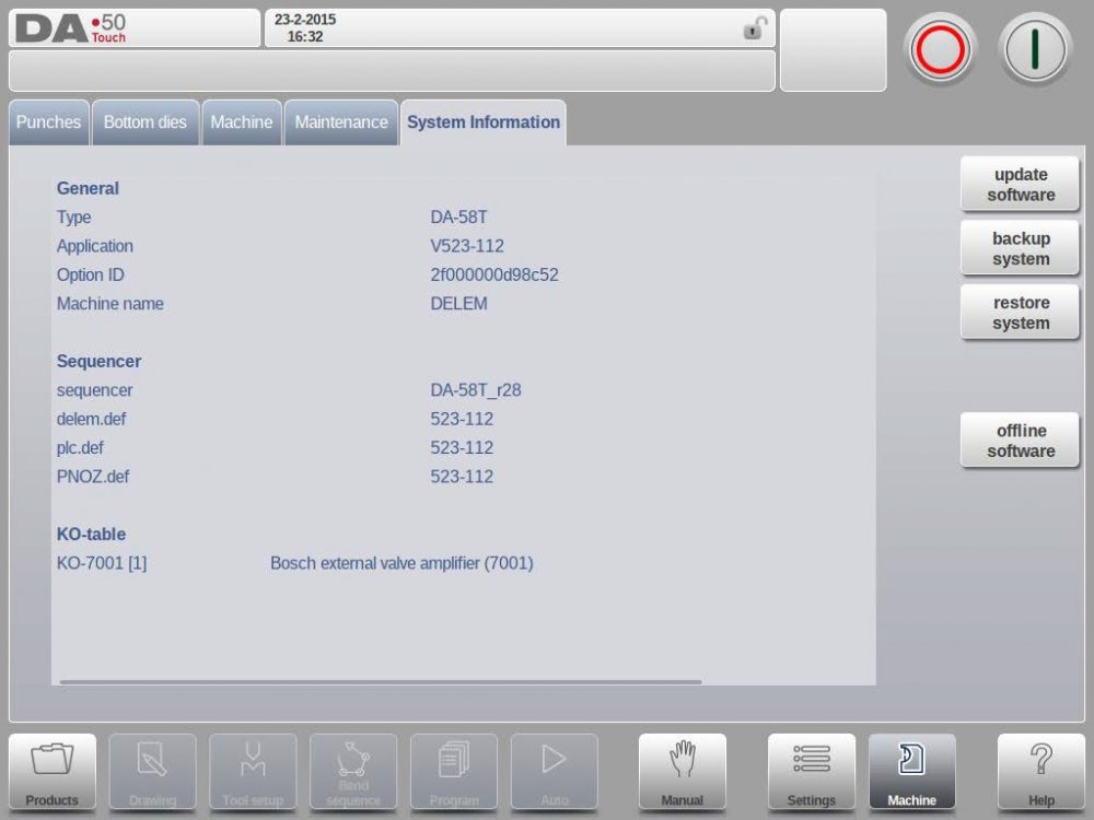
Изменено пользователем xedex
-
Как выбрать стойку ЧПУ для листогибочного пресса
-
Delem DA-53T
-
Delem DA-58T
-
Delem DA-66T
-
Delem DA-69T
-
Листогибочные прессы Abamet с системой ЧПУ Delem
Когда речь заходит о выборе листогибочного пресса, один из наиболее важных моментов, которому следует уделить внимание, — это система ЧПУ. Стойки ЧПУ Delem по праву пользуются большой популярностью среди производителей листогибов, потому как обладают широким набором функций для комфортного программирования и управления гибочными станками и отличаются удобным русифицированным интерфейсом. Кроме того, Delem предлагает офлайн программное обеспечение, в котором инженер-технолог может проверить, как согнется деталь, начерченная конструктором, и какой для этого будет нужен инструмент.
Основное распространение получили следующие модели Delem:
DA-53T
,
DA-58T
,
DA-66T
и
DA-69T
. Чем же они отличаются, и какая стойка подойдет именно вам? Ответы на эти вопросы вы найдете в этой статье.
Как выбрать стойку ЧПУ для листогибочного пресса
Итак, как выбрать такую стойку, которая будет полностью отвечать требованиям вашего производства, но при этом не переплатить? Как и при выборе станка в целом, здесь нужно отталкиваться от ваших задач. Какие детали вы планируете гнуть? Какая у них будет конфигурация, насколько сложные формы вам требуется получить? В каких осях должны перемещаться задние упоры? Планируете ли вы работать серийно, изготавливать стандартные детали, или же вам предстоит постоянно перенастраивать станок под новые задачи? Нужен ли вам импорт DXF и 3D-файлов? Ответив на эти вопросы, вы сможете подобрать стойку, которая подходит именно вам.
Ниже приведена сравнительная таблица стоек Delem DA-53T, DA-58T, DA-66T и DA-69T.
Основные характеристики контроллеров ЧПУ Delem
|
DA-53T |
DA-58T |
DA-66T |
DA-69T |
|
|---|---|---|---|---|
| Характеристики дисплея | TFT-дисплей с диагональю 10.1″ | TFT-дисплей с диагональю 15″ | TFT-дисплей с диагональю 17″ | TFT-дисплей с диагональю 17″ |
| Разрешение экрана | 1024х600 | 1024х768 | 1280х1024 | 1280х1024 |
| Объем жесткого диска | 1 ГБ | 1 ГБ | 1 ГБ | 2 ГБ |
| Объем памяти для программ и инструмента | 256 МБ | 256 МБ | 256 МБ | 256 МБ |
| Количество разъемов USB | 1 | 1 | 2 | 2 |
| Количество сетевых разъемов Ethernet (RS232) | 0 | 1 | 2 | 2 |
| Программирование | Числовое, графическое (опционально) | Числовое, графическое | Числовое, графическое, импорт DXF (опционально) | Числовое, графическое, импорт DXF и 3D |
| Режим визуализации гибки | Числовой, графический в формате 2D (опционально) | Числовой, графический в формате 2D | Числовой, графический в формате 3D | Числовой, графический в формате D |
| Библиотека инструмента | 30 пуансонов, 30 матриц | 30 пуансонов, 60 матриц | Без ограничений | Без ограничений |
| Библиотека материалов и данных по коррекциям углов | Да | Да | Да | Да |
| Программирование инструмента | Числовое, графическое (опционально) | Числовое, графическое | Числовое, графическое | Числовое, графическое |
| Программирование многопозиционной расстановки инструментов | Нет | Нет | Да | Да |
| Подключение к сети | Нет | Да | Да | Да |
| Максимальное количество управляемых осей | 4+1 (Y1, Y2, X, R) | 4+1 (Y1, Y2, X, R) | 8+1 (Y1, Y2, X1, X2, Z1, Z2, R1, R2) | 8+1 (Y1, Y2, X1, X2, Z1, Z2, R1, R2) |
| Управление системой ЧПУ-бомбирования | Да | Да | Да | Да |
| Сохранение данных при аварийном отключении электропитания | Да | Да | Да | Да |
| Система диагностики и индикации ошибок | Да | Да | Да | Да |
| Импорт DXF | Нет | Нет | При установке опции «Импорт DXF для Delem DA-66T» | Да |
| Импорт 3D | Нет | Нет | Нет | Через офлайн ПО |
| Пыле- и влагозащищенность | IP54 | IP54 | IP54 | IP54 |
| Офлайн ПО в комплекте | Delem Profile-TL | Delem Profile-T2D | Delem Profile-T2D | Delem Profile-T3D |
Delem DA-53T
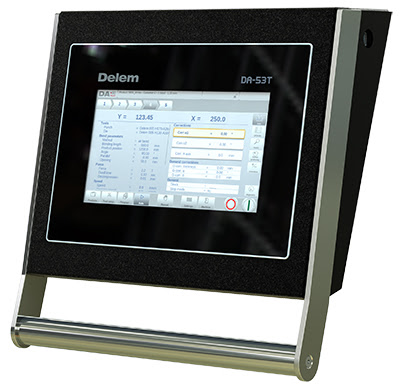
Стойка Delem DA-53T
Стойка ЧПУ Delem DA-53T — это отличное решение для производств с небольшой номенклатурой деталей несложной формы, таких как: профили различных конфигураций, кронштейны, простые коробки квадратной и прямоугольной формы и т.п. Эта стойка обладает небольшим сенсорным экраном с диагональю 10.1″ и может управлять максимум 4 осями, не считая оси бомбирования. В такой конфигурации упоры будут автоматически перемещаться только по осям X и R, перемещать их по оси Z придется вручную. Кроме того, с этой стойкой вы не сможете готовить программы для угловых гибов, которые требуют управления осью ΔX. Данная стойка может хранить в памяти до 30 пуансонов и матриц.
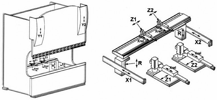
Схема осей листогибочного пресса
В стандартной комплектации Delem DA-53T доступно только числовое программирование и визуализация гибов, но при установке дополнительной опции «2D программирование для DA-53T» откроется возможность графического программирования. В этом режиме оператор может вручную начертить профиль гиба, проставить нужные углы и размеры, а стойка сама рассчитает координаты каждой оси для каждого гиба. Визуализация гибов также будет отображаться в 2D-формате. В комплекте со стойкой поставляется ПО для технолога Delem Profile-TL, в котором доступно только числовое программирование.
Delem DA-58T
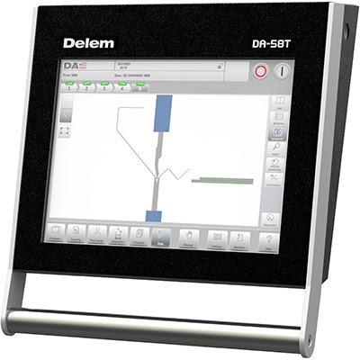
Стойка Delem DA-58T
Стойку ЧПУ Delem DA-58T можно назвать продвинутой версией
DA-53T
. Как и Delem DA-53T, DA-58T может управлять максимум 4 осями, не считая оси бомбирования. При этом стойка оснащена удобным экраном с диагональю 15″, функцией 2D-программирования и симуляции гиба. Библиотека инструмента увеличена — 30 пуансонов и 60 матриц. Кроме того, в комплекте со стойкой идет ПО для технолога Delem Profile-T2D. В этой версии вы сможете подготовить числовые и графические программы на компьютере, не подходя к станку.
Delem DA-66T
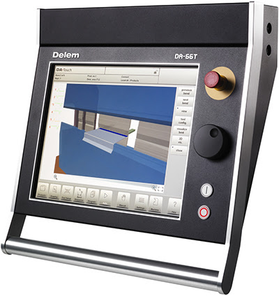
Стойка Delem DA-66T
Стойка ЧПУ Delem DA-66T сильно отличается от предыдущих моделей в плане функциональности и удобства работы. Максимальное количество управляемых осей = 8+1 (Y1, Y2, X1, X2, R1, R2, Z1, Z2 и система бомбирования). Это значит, что с этой стойкой вы сможете согнуть самые сложные детали. Библиотека инструмента не ограничена. При установке опции «Импорт DXF для Delem DA-66T» вы сможете импортировать 2D чертежи в ЧПУ и офлайн ПО Delem Profile-T2D. Однако следует сказать, DA-66T в этом функционале несколько ограничена: можно импортировать чертежи с гибами только в одной плоскости. Если вам нужны детали с перпендикулярными гибами (коробки, корпуса и т.д.), вам понадобится ПО Profile-T3D. Стойка обладает отличным экраном с диагональю 17″ и визуализирует гибку детали в 3D, то есть оператор всегда сможет подробно рассмотреть, как ему нужно позиционировать деталь при гибе, а это бывает очень полезным при работе с изделиями сложной формы.
Delem DA-69T
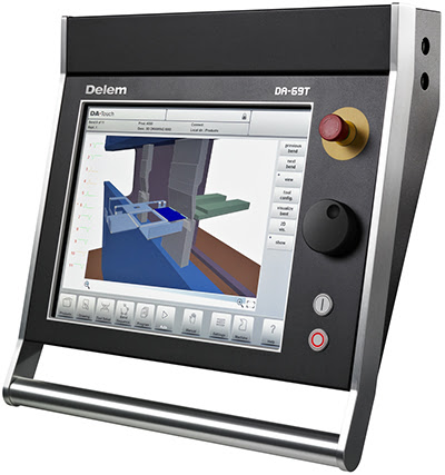
Стойка Delem DA-69T
Стойка ЧПУ Delem DA-69T — самая удобная и функциональная стойка из всех перечисленных. Диагональ экрана — 17″. Как и Delem DA-66T, может управлять 8 осями и системой ЧПУ-бомбирования. DXF-файлы можно импортировать напрямую в стойку, в том числе чертежи с перпендикулярными гибами. Импорт 3D доступен через офлайн ПО Delem Profile T3D. Симуляция гиба в 3D, неограниченная библиотека инструмента. В комплекте со стойкой поставляется наиболее продвинутая версия ПО для технолога — Delem Profile-T3D. В общем, если вам нужен топовый контроллер для гибки листового металла — это определенно он.
Листогибочные прессы Abamet с системой ЧПУ Delem
Компания «Абамет» более 20 лет занимается поставками листогибочных прессов. Все это время мы успешно сотрудничали с известными производителями станков из Европы и Азии, проверяли в деле различные комплектующие и конфигурации станков, вместе с клиентами решали их технологические задачи, а наши инженеры сделали сотни выездов по сервисным заявкам. Большой накопленный опыт позволяет нам с уверенностью утверждать, что стойки Delem — пожалуй, лучшее решение на рынке контроллеров ЧПУ для листогибочных прессов. Интуитивно понятный интерфейс, удобное управление, огромное количество сервисных параметров для настройки станка, визуализация гибов в 3D, импорт DXF и 3D, офлайн ПО в комплекте — все это вместе делает выбор стойки ЧПУ очевидным.
Сейчас наша компания предлагает сервогидравлические листогибы серии AMBA и электромеханические листогибы серии AMBE.
Станки серии AMBA
— это листогибы, обладающие всем необходимым для решения большинства технологических задач. Сервогидравлическая система обеспечивает быстрое и точное движение верхней балки, в базовой комплектации перемещения упоров автоматизированы по осям X и R, установлена система ЧПУ-бомбирования (компенсации прогиба). Система ЧПУ —
Delem DA-53T
, также доступны
DA-58T
,
DA-66T
,
DA-69T
. Станок может быть оснащен дополнительными опциями, в том числе, автоматизацией осей перемещения упоров, системой лазерной защиты, системой крепления инструмента Wila и т.д.
Станки серии AMBE
отличаются электромеханическим приводом перемещения верхней балки, что позволяет достичь большей производительности при снижении уровня шума. Из-за своих небольших размеров и тоннажа идеально подходят для производства небольших деталей сложной формы: контактные группы, фурнитура и т.п. В базовой комплектации станки оснащены стойкой Delem DA-53Tx (обновленная версия
DA-53T
, отличающаяся большим экраном и возможностью управления 6 осей). Опционально доступны
DA-66T
,
DA-69T
.
Is your DA-53T smart press brake operating efficiently? Proper operation of the Smart Press Brake is essential for high-precision bending and improved productivity.
Learn how to optimize your DA-53T Smart Press Brake for precision, efficiency, and long-term reliability. This guide covers key operational steps and tips for mastering your press brake control system.
Let’s explore the essential steps to get your DA-53T Smart Press Brake up and running smoothly.
Applicable for DA-53T Smart Press Brake

HARSLE has recorded a detailed operating tutorial of the Smart Press Brake DA-53T to help the new customer to use our press brake faster and better. This tutorial records from oil injection to switch off, it also shows some specific functions of DELEM DA-53T. We hope this will be helpful to you;
Part 1 Fill Oil + Cable Connections
Filling the oil tank with anti-wear hydraulic oil
Properly filling the oil tank with anti-wear hydraulic oil is crucial for ensuring the smooth operation and longevity of your DA-53T Smart Press Brake. Before filling, ensure the hydraulic tank is clean and free from contaminants. Use high-quality anti-wear hydraulic oil (such as ISO VG 46 or 68), which enhances lubrication and minimizes wear. Slowly pour the oil into the tank while monitoring the oil level gauge to prevent overfilling. After filling, allow the oil to settle, then check for leaks and ensure proper circulation by running the hydraulic system. Regular oil checks and maintenance will keep your machine running efficiently.

No less than Two-thirds of the Oil Volume Level
Ensuring that the hydraulic oil level remains at no less than two-thirds of the reservoir’s capacity is crucial for the efficient operation of the DA-53T Smart Press Brake. Insufficient oil levels can lead to inadequate hydraulic pressure, increased wear on components, and potential malfunctions in the bending process. Maintaining the correct oil volume helps in reducing friction, preventing overheating, and ensuring smooth machine operation. Regularly check the oil level and top it up as needed with the recommended hydraulic fluid. This simple maintenance step extends the machine’s lifespan, enhances precision, and prevents unexpected breakdowns, keeping production efficient and reliable.

Connect the machine to the power source
Before operating the DA-53T Smart Press Brake, ensure the machine is properly connected to a stable power source. Verify that the voltage and frequency meet the machine’s specifications to prevent electrical damage. Use a dedicated power line with sufficient capacity to handle the press brake’s load. Securely connect the power cable to the designated input port and check for any loose connections. Once connected, switch on the main power supply and observe the control panel for any error warnings. If the machine does not power on or displays an error, inspect the connections and consult the user manual for troubleshooting.

Properly Connecting the Cable to the Electrical Box
Before connecting the cable to the electrical box, ensure that the machine is powered off and properly grounded for safety. Identify the designated cable entry point on the electrical box and remove any protective covers. Carefully insert the cable through the cable gland, securing it to prevent movement. Connect each wire to the appropriate terminal according to the wiring diagram, ensuring firm and correct placement. Double-check all connections to avoid loose or incorrect wiring, which may cause malfunctions. Once secured, fasten the cable gland and reinstall any covers. Finally, test the connection by powering on the machine to confirm proper functionality.

Connect the earth wire
Connecting the earth wire is a crucial step to ensure the safe and stable operation of your DA-53T Smart Press Brake. Before starting, make sure the machine is powered off to avoid any electrical hazards. Locate the grounding terminal on the press brake and use a properly rated copper wire to establish a secure connection to a reliable ground source. This step helps prevent electrical leakage, reduces interference, and enhances overall safety. A poor or missing ground connection can lead to electrical malfunctions and potential risks. Always follow local electrical codes and manufacturer guidelines for proper grounding.

Switch on the power source
Before operating the DA-53T Smart Press Brake, ensure that the power source is properly connected. Locate the main power switch, typically positioned on the side or back of the machine. Turn the switch to the “ON” position and wait for the system to initialize. The controller screen should light up, indicating a successful startup. Check for any error messages or system alerts before proceeding. Additionally, verify that all emergency stop buttons are released and that the hydraulic system is ready for operation. Ensuring a proper power-up process helps maintain machine longevity and prevents potential malfunctions during operation.

Connect the pedal switch to the machine
To ensure smooth and efficient operation of the DA-53T Smart Press Brake, it is essential to correctly connect the pedal switch to the machine. Start by locating the designated pedal connection port on the press brake. Align the connector properly and insert it securely, ensuring a firm and stable connection. Tighten any locking mechanisms to prevent accidental disconnection during operation. Once connected, test the pedal function by pressing it lightly to confirm responsiveness. A properly connected pedal switch enhances operator control, improves precision, and ensures safe machine operation. Always check for loose connections before starting a bending task.

Turn on the machine power switch
Before operating the DA-53T Smart Press Brake, ensure that the machine is properly installed and all safety precautions are in place. Begin by locating the main power switch, usually positioned on the side or back of the machine. Turn the switch to the “ON” position to activate the electrical system. Wait for the control panel to initialize and check for any system notifications or errors. Ensure that the emergency stop button is released and that all safety devices are functioning correctly. Once powered on, the DA-53T controller will be ready for further setup and programming.

Waiting for the system loading
When powering on the DA-53T Smart Press Brake, the system undergoes an initialization process to ensure all components function correctly. During this time, the screen will display a “Waiting for the system loading” message. This process allows the machine to run diagnostic checks, load essential software, and verify system configurations. It is important not to interrupt the loading sequence to prevent potential errors. Depending on the machine’s setup, this may take a few seconds. Once completed, the home screen will appear, allowing operators to access the control panel and begin programming the bending process efficiently.

Checking Motor Rotation & Operating Soft Buttons on DA-53T
Before operating the DA-53T Smart Press Brake, it is essential to check the main motor’s rotating direction to ensure proper machine functionality. A reverse rotation may cause malfunctions or performance issues. If the direction is incorrect, adjust the wiring accordingly.
Once the motor rotation is verified, proceed by pulling down the soft buttons on the DA-53T controller to activate the system. These soft buttons allow for smooth navigation and precise control of bending operations. Properly following these steps ensures efficient and safe machine operation, minimizing downtime and improving bending accuracy. Always confirm system readiness before proceeding with production tasks.

Press the pump-start button shortly
To begin operating the DA-53T Smart Press Brake, you first need to activate the hydraulic system by pressing the pump-start button briefly. This action initializes the machine’s power supply and engages the hydraulic pump, allowing pressure to build up for smooth and precise bending operations. Ensure that the emergency stop button is released, and the power supply is stable before pressing the pump-start button. Once the system is activated, check the control panel display to confirm that all machine parameters are set correctly. This simple step ensures that the press brake is ready for efficient and safe operation.

Verify and Adjust the DA-53T Press Brake Motor Rotation
Before operating the DA-53T Smart Press Brake, it is crucial to verify the main motor’s rotating direction. After powering on the machine, observe the motor’s rotation. If it rotates clockwise, the direction is correct, and the machine is ready for use. However, if the motor rotates counterclockwise, it indicates an incorrect wiring connection. To fix this, exchange the two power wires of the motor and recheck the rotation. Ensuring the correct direction is essential to prevent performance issues and potential damage. Always follow safety guidelines when handling electrical connections to avoid accidents or equipment malfunctions.

Part 2 Machine Start-up
Turn on the machine power switch
Before operating the DA-53T Smart Press Brake, the first step is to turn on the machine power switch. Locate the main power switch on the control panel or electrical cabinet and ensure that the power supply is stable. Turn the switch to the “ON” position and wait for the system to initialize. The CNC controller will start up, displaying the main interface. Check for any error messages or system alerts before proceeding. Make sure the emergency stop button is released, and confirm that all safety mechanisms are active. Once the system is fully powered, the machine is ready for operation.

Waiting for the system loading
When starting up the DA-53T Smart Press Brake, the system requires a brief initialization process. During this time, the machine is loading essential data, configuring its settings, and ensuring that all components are properly synchronized. This step is crucial for optimal performance and accuracy during operation. Users should patiently wait for the system to complete loading before proceeding with any bending tasks. Interrupting the process may cause software errors or incomplete system configurations. Once the system is fully loaded, the main interface will appear, allowing you to select bending programs, adjust parameters, and start metal bending operations efficiently.


Pull down the soft buttons
To operate the DA-53T Smart Press Brake efficiently, you need to understand how to use its soft buttons on the touchscreen interface. These virtual buttons allow users to navigate different functions quickly. By pulling down the soft buttons, operators can access essential bending parameters, tool settings, and machine configurations. This feature enhances workflow efficiency, reducing setup time and improving accuracy. The intuitive design ensures that even new users can operate the machine with minimal training. Mastering this function helps optimize productivity and ensures precise, high-quality metal bending results every time.

Turn on the lights
Turning on the lights is a simple yet essential action in daily life. It brightens up a space, enhances visibility, and improves safety by preventing accidents in dim environments. Proper lighting also boosts productivity, whether at home, in an office, or in a workshop. In manufacturing and metal fabrication, good lighting ensures precision and accuracy when operating machines like press brakes. Additionally, the right lighting can create a comfortable atmosphere, reducing eye strain and enhancing focus. Whether for work, safety, or ambiance, turning on the lights plays a crucial role in improving efficiency and overall well-being.

Press the pump-start button
Before operating the DA-53T Smart Press Brake, ensure that the machine is properly set up and all safety checks are completed. To start the hydraulic system, locate the pump-start button on the control panel. Press the button firmly, and you will hear the hydraulic pump activate, indicating that the system is now powered. Wait a few seconds to allow the pump to reach its optimal pressure. If the machine displays any alerts, check the error messages before proceeding. A properly functioning hydraulic pump ensures smooth and precise bending operations, reducing errors and enhancing efficiency in metal fabrication.

Press the start button and find reference points
To begin operating the DA-53T Smart Press Brake, press the start button to power on the machine. Once the system initializes, it is crucial to locate the reference points for accurate bending. The machine will automatically move the backgauge and ram to their predefined positions, ensuring proper alignment. This step is essential for precision bending and consistent results. If the reference points are not set correctly, the machine may produce inaccurate bends. Always verify that the CNC controller displays the correct positioning before proceeding with further operations. This ensures smooth workflow and enhances the overall efficiency of the bending process.

Finding reference points is done
Finding reference points is a crucial step when operating the DA-53T Smart Press Brake, ensuring precise positioning for accurate bending. This process involves setting the X, Y, and R axes to establish a baseline for repeatable and consistent bends. The machine automatically detects the reference points through its CNC system, allowing operators to achieve high precision in metal fabrication. Proper calibration of these points minimizes errors and enhances production efficiency. Regularly checking and adjusting reference positions is essential to maintain accuracy. Mastering this step is key to optimizing the DA-53T press brake’s performance for high-quality bending results.

Test the X-axis running
Before operating the DA-53T Smart Press Brake, it is crucial to test the X-axis running to ensure smooth and precise backgauge movement. Start by accessing the DA-53T controller, navigating to the manual mode, and incrementally moving the X-axis forward and backward. Observe whether the movement is stable and whether the positioning matches the programmed values. If any deviations occur, recalibrate the backgauge system through the controller settings. Additionally, inspect for mechanical obstructions or loose connections that might affect accuracy. Performing this test regularly helps maintain high precision bending, reduces errors, and extends the machine’s lifespan.

Test the R-axis running
Testing the R-axis running on a DA-53T Smart Press Brake ensures precise vertical movement of the backgauge fingers, which is essential for accurate step bending and multi-stage bending processes. To perform the test, access the CNC controller interface, navigate to the R-axis settings, and manually or automatically move the backgauge fingers up and down. Verify the movement’s smoothness, precision, and repeatability by checking position accuracy. If misalignment or irregular motion occurs, recalibrate the R-axis and inspect for mechanical obstructions. Regular testing of the R-axis improves bending accuracy, reduces setup time, and enhances overall press brake performance.

Test the crowning system running
To ensure precise bending results, it is essential to test the crowning system on the DA-53T Smart Press Brake before operation. Start by selecting a test material and setting a moderate bending angle. Activate the crowning compensation feature on the DA-53T controller, ensuring it adjusts for material deformation. Perform a test bend and measure the consistency along the entire workpiece. If deviations occur, fine-tune the crowning settings accordingly. Regular testing prevents angle discrepancies and ensures high-precision bending for complex metal parts. This step is crucial for maintaining efficiency and extending the lifespan of the machine’s components.

Check the tooling parameters
Before operating the DA-53T Smart Press Brake, it is essential to check the tooling parameters to ensure accurate bending results. Start by verifying that the punch and die dimensions match the programmed settings in the DA-53T controller. Incorrect tooling parameters can lead to inaccurate bends, material waste, or even machine damage. Additionally, inspect the tooling for wear and alignment to maintain consistency in production. Always refer to the machine’s manual for recommended tool settings and adjustment procedures. Proper tooling verification not only enhances precision but also prolongs the lifespan of your press brake.

Measure the tooling to compare with the data
Before operating the DA-53T Smart Press Brake, it is essential to measure the tooling accurately and compare it with the preset data in the control system. Use a precise caliper or micrometer to measure the height, angle, and width of the punch and die. Ensure that the tooling dimensions match the programmed values to prevent bending errors and misalignment. If discrepancies are found, adjust the settings accordingly in the DA-53T controller. Proper tooling measurement not only enhances bending accuracy but also extends the tool’s lifespan, reducing production errors and improving overall efficiency in sheet metal fabrication.

Part 3 Bending Programming
Input the password 42
To access certain settings or perform advanced functions on the DA-53T Smart Press Brake, users may need to input a password. The default password is 42, which allows operators to enter the machine’s configuration or perform system adjustments. To input the password, navigate to the settings menu, locate the password entry field, and enter 42 using the touchscreen keypad. Once entered, press OK to confirm. If the system does not accept the password, ensure that it is entered correctly or check with the machine administrator for any customized credentials. Always follow manufacturer guidelines to prevent unauthorized changes.

Input the product ID
To ensure precise bending operations, correctly inputting the product ID on the DA-53T Smart Press Brake is essential. Start by navigating to the control panel and selecting the product management menu. Enter the designated product ID, which corresponds to your pre-set bending program. This helps streamline production by quickly recalling stored parameters. Double-check the ID entry to avoid errors that may impact bending accuracy. Once entered, save the settings and confirm them before starting operations. Properly managing product IDs enhances efficiency, reduces setup time, and ensures consistent results in sheet metal bending applications.

Input the sheet thickness
Accurately inputting the sheet thickness on the DA-53T Smart Press Brake is essential for precise bending results. Navigate to the material settings on the DA-53T controller and enter the correct sheet thickness in millimeters. This value determines the bending force, compensation, and crowning adjustments needed for optimal accuracy. Incorrect thickness input may result in over-bending or under-bending, affecting part quality. Always verify the sheet thickness using a caliper before inputting the value. Ensuring this step is correctly set improves bending efficiency and reduces errors, leading to higher repeatability and accuracy in metal fabrication.

Selecting the tooling
Selecting the correct tooling is crucial for achieving precise and efficient bending with the DA-53T Smart Press Brake. The right combination of punches and dies directly impacts bending accuracy, material handling, and overall machine performance. When choosing tooling, consider factors such as material type, thickness, bending angle, and required precision. Standardized tool sets offer versatility, while custom tooling enhances performance for specialized applications. Regular maintenance and proper installation ensure longevity and consistent results. Investing in high-quality press brake tooling not only improves bending accuracy but also extends the machine’s lifespan, reducing downtime and increasing production efficiency.

Input the bending length
To ensure accurate bending operations, correctly inputting the bending length on the DA-53T Smart Press Brake is crucial. Start by navigating to the programming interface on the DA-53T controller. Locate the bending length field and enter the exact measurement of the workpiece. Ensure the value aligns with the material’s actual dimensions to avoid misalignment. Double-check the input to prevent errors in bending angles and positioning. Once entered, confirm the data and proceed with the next steps in the bending process. Accurate length input guarantees precision, efficiency, and consistency in every metal bending task.

Input the bending angle
To ensure precise bending results, correctly inputting the bending angle on the DA-53T Smart Press Brake is crucial. Start by accessing the bending program on the controller. Select the desired bending step and locate the angle input field. Enter the required bending angle based on your material type and thickness. The DA-53T system will automatically calculate the required ram depth to achieve accurate bending. After input, verify the angle settings and perform a test bend to confirm accuracy. Adjust if necessary to compensate for material springback. This process ensures consistent and high-precision bending performance.

Enter the X-axis distance
Entering the X-axis distance on the DA-53T Smart Press Brake ensures accurate positioning of the backgauge for precise metal bending. To set the X-axis distance, navigate to the controller interface, locate the X-axis input field, and enter the required value based on your bending specifications. The system will automatically adjust the backgauge to match the set distance, ensuring consistent results. Always double-check your measurements before confirming the input to prevent misalignment. Properly setting the X-axis is crucial for achieving accurate bends, reducing rework, and improving efficiency in CNC press brake operations.

Add the second bending step
To add the second bending step on the DA-53T Smart Press Brake, follow these steps for a smooth and precise operation. First, navigate to the programming interface and select the existing bending sequence. Click on “Add Step” and enter the necessary parameters, including bending angle, material thickness, and die selection. Adjust the backgauge position to ensure proper alignment for the second bend. Perform a test bend to verify accuracy before proceeding with production. This step ensures consistency in multi-stage bending operations, improving product quality and efficiency. Always double-check the tooling setup to avoid misalignment and errors.

Check program data
Before starting the bending process, it is crucial to check the program data on the DA-53T Smart Press Brake to ensure accurate and efficient operations. Verify that the bending sequence, material thickness, tooling selection, and backgauge positions are correctly set in the controller. Carefully review angle settings and adjust parameters if needed. Double-check safety features and clearance to prevent collisions. Running a simulation or test bend can help identify potential errors before full production. By thoroughly reviewing program data, operators can enhance precision, reduce material waste, and improve overall efficiency in metal bending operations.

Ready to start
Ready to start operating your DA-53T Smart Press Brake? This advanced CNC system offers precise control, user-friendly navigation, and enhanced efficiency for metal bending operations. Whether you’re a beginner or an experienced operator, understanding the key functions of the DA-53T is essential for maximizing productivity and achieving accurate bends. In this guide, we’ll walk you through the startup process, parameter settings, and operational best practices to ensure smooth performance. By mastering the DA-53T controller, you can enhance workflow efficiency and minimize errors in sheet metal fabrication. Let’s get started on optimizing your press brake operations!

Part 4 Bending Products
Positioning the Metal Sheet for Precise Bending
To begin the bending process, carefully place the metal sheet onto the worktable of the DA-53T Smart Press Brake. Ensure that the sheet is positioned correctly, aligning it with the backgauge stop fingers. The stop fingers serve as precise reference points, ensuring accurate bending angles and repeatability. Gently slide the sheet until it makes full contact with the stop fingers, preventing misalignment. Proper sheet positioning is essential for achieving consistent and high-quality bends. Double-check that the material is lying flat against the worktable to avoid inaccuracies during the bending operation. Once aligned, proceed with the bending cycle.

Step the pedal
Once all parameters are set on the DA-53T Smart Press Brake, the next step is to activate the bending process by stepping on the pedal. The pedal serves as the main control for initiating and controlling the bending motion. Pressing the pedal engages the hydraulic system, lowering the upper beam to press the sheet metal against the die. For safety, ensure your foot remains on the pedal until the bending cycle is complete. If an emergency occurs, release the pedal immediately to halt the operation. Proper pedal control ensures precision, efficiency, and safety in metal bending operations.

Complete Step one
Before operating the DA-53T Smart Press Brake, ensure that the machine is properly connected to the power supply and that all safety checks are completed. Turn on the main switch and wait for the control system to initialize. Once the DA-53T controller boots up, verify the system status, including hydraulic pressure, backgauge position, and tool alignment. Select the correct bending program or create a new one based on the material specifications. Adjust the press brake tooling if necessary. Always confirm that the emergency stop button is functional before proceeding to the next step.

Press the pedal
Pressing the pedal is a crucial step in operating the DA-53T Smart Press Brake efficiently. The foot pedal controls the bending process, allowing the operator to activate and stop the machine hands-free. To ensure smooth operation, position your foot correctly on the pedal and apply steady pressure. Most press brakes feature a dual-function pedal, where one side initiates the bending motion while the other reverses it. Always check the responsiveness before starting production to avoid misalignment or errors. Additionally, maintaining a clean workspace around the pedal prevents accidental activation, enhancing safety and precision in sheet metal bending.

Complete Step two
Before starting the bending process, you must configure the DA-53T Smart Press Brake controller correctly. Begin by powering on the machine and accessing the main interface. Select the appropriate bending program or create a new one based on your workpiece specifications. Input key parameters such as material type, thickness, bending angle, flange length, and tool selection. Ensure the backgauge position is set correctly for precise bends. Use the graphical interface to verify settings and simulate the bending process before execution. Proper configuration of the DA-53T controller ensures high-precision bending and minimizes material waste. Always save your settings for future use.

Part 5 Measurement And Calibration
Measure the first bending distance
Before starting the bending process on the DA-53T Smart Press Brake, it is crucial to accurately measure the first bending distance to ensure precision and consistency. Begin by referencing the bending program on the DA-53T controller, verifying the back gauge position and tool alignment. Use a calibrated measuring tool to check the distance from the edge of the sheet to the bending line. Make minor adjustments in the controller if necessary. A precise first bend is essential for maintaining correct angles and dimensions throughout the process. Always double-check the setup before proceeding with mass production to avoid errors and material waste.

Measure the second bending distance
Measuring the second bending distance accurately is crucial to ensuring precision in sheet metal bending. After completing the first bend, carefully reposition the workpiece according to the programmed dimensions. Use the CNC backgauge on the DA-53T Smart Press Brake to set the exact position, ensuring consistent alignment. Verify the distance using a caliper or a ruler to confirm accuracy before proceeding with the next bend. Adjustments can be made via the controller if minor deviations occur. Proper measurement and alignment help achieve uniform bends, reduce errors, and enhance overall production efficiency. Always double-check settings before executing the bend.

Measure Bending Angles Accurately with an Angle Ruler
Using an angle ruler is essential for ensuring precise bending angles on a DA-53T Smart Press Brake. To achieve accurate measurements, position the angle ruler at three key locations: left, middle, and right of the bent workpiece. This method helps identify any inconsistencies across the bend, ensuring uniformity. If variations are detected, adjustments can be made to the back gauge, crowning system, or bending force. Consistently measuring angles at multiple points improves bending precision, reducing material waste and rework. Always verify the readings before finalizing the bend to maintain quality in sheet metal fabrication.

Error found: Measured at 91°
An error has been detected during the bending process, with the measured angle recorded at 91° instead of the expected value. This deviation may be caused by factors such as incorrect material positioning, improper tool selection, or backgauge misalignment. To resolve this issue, first, check whether the press brake tooling and workpiece are properly aligned. Then, verify the bending force settings and recalibrate the machine if necessary. Additionally, inspect for any wear or deformation in the punch and die. Making these adjustments can help ensure accurate bending results and improve overall efficiency in metal fabrication.

Enter the calibration parameters -1
To ensure precise bending operations, entering the correct calibration parameters in the DA-53T Smart Press Brake is essential. Start by accessing the system settings on the controller interface. Navigate to the calibration menu, where you can input values such as Y-axis reference points, backgauge position, and angle compensation. Carefully adjust these parameters based on the material thickness and tooling setup. Once entered, perform a test bend to verify accuracy. If necessary, fine-tune the settings to achieve the desired bending results. Proper calibration minimizes errors, enhances repeatability, and ensures optimal press brake performance in metal fabrication processes.

Bend again for testing
After setting up the bending parameters, it’s essential to bend again for testing to ensure accuracy and consistency. This step verifies whether the programmed angles and dimensions align with the desired results. If the bend is incorrect, adjustments in the back gauge, pressure, or angle correction settings may be required. Conducting a second test bend helps eliminate errors and fine-tune the machine for optimal performance. Regular testing not only improves precision but also reduces material waste and enhances production efficiency. Always inspect the test bend carefully to confirm that it meets the required specifications before proceeding with full-scale production.

The Importance of Measuring Again in Press Brake Operations
Precision is critical in press brake operations, and measuring again ensures accuracy in every bend. Even a slight miscalculation can lead to material waste, rework, and production delays. Before finalizing a bend, always double-check the material positioning, backgauge settings, and programmed angles. Measuring again helps identify any misalignment, compensates for material variations, and ensures the final product meets the required specifications. This simple yet essential step can save costs, improve efficiency, and enhance overall quality. Whether you are a beginner or an experienced operator, making it a habit to measure again will significantly reduce errors and optimize production.

It is correct now
It is correct now. Ensuring the proper operation of the DA-53T Smart Press Brake is essential for achieving precise and efficient bending results. By following the correct setup and programming procedures, operators can maximize machine performance, reduce errors, and extend the tool’s lifespan. Key factors include accurate parameter settings, proper tooling selection, and routine maintenance. The DA-53T controller simplifies operations with its intuitive touchscreen interface and smart bending functions, making it easier to execute complex bending tasks. Mastering these techniques helps improve productivity and ensures high-quality metal fabrication results, meeting industry standards with ease.

Part 6 Other Functions
Laser Protection
Laser protection is a crucial safety feature in modern press brakes, ensuring operator safety during metal bending operations. To activate the laser protection system, simply input “01” into the controller. This enables the real-time safety monitoring of the bending area, preventing accidental injuries by automatically detecting any obstruction. The system ensures precise and uninterrupted operation while maintaining safety compliance. Always verify that the laser protection is functioning correctly before starting production. By integrating laser protection, you enhance workplace safety without compromising efficiency. Regular maintenance and calibration of the laser system will further improve performance and reliability.

The slider will brake immediately once the laser is blocked
The DA-53T Smart Press Brake is equipped with an advanced laser safety system that ensures operator protection during metal bending operations. As soon as the laser beam is interrupted, the slider (ram) will immediately stop and brake, preventing any potential accidents or damage. This real-time safety feature enhances workplace security and minimizes the risk of injury. The high-speed response of the system allows for smooth yet secure operation, ensuring both efficiency and precision. With intelligent laser monitoring, operators can work with confidence, knowing that their safety is always a priority. Upgrade your press brake with smart safety technology!

Input 00 to close laser protection
To ensure safe operation of the DA-53T Smart Press Brake, the laser protection system must be properly managed. If you need to disable the laser protection feature, navigate to the input settings and set Input 00 to “Close”. This will deactivate the laser safety mechanism, allowing manual adjustments or special bending operations that require temporary laser protection deactivation. However, always exercise caution when disabling this feature and re-enable it once the required adjustments are complete. Safety should be a top priority to prevent potential accidents. Always follow the DA-53T operational guidelines for safe and efficient press brake use.

The slider will run normally even if the laser is blocked
The DA-53T Smart Press Brake is designed with advanced motion control technology, ensuring that the slider operates smoothly even if the laser safety system is momentarily blocked. This means that minor obstructions or temporary interference with the laser sensors will not disrupt the machine’s bending process. Instead of an abrupt stop, the system maintains stable movement, reducing downtime and improving overall efficiency. This feature enhances workshop productivity, ensuring continuous operation while maintaining safety standards. Operators can rely on this intelligent system to deliver precision bending without unnecessary interruptions, improving workflow efficiency in metal fabrication.

Pedal Control ModeSwitch
The Pedal Control Mode Switch on the DA-53T Smart Press Brake plays a crucial role in improving efficiency and ease of operation. This feature allows operators to seamlessly switch between different control modes using the foot pedal, freeing their hands for better positioning and material handling. With precise foot control, users can start, stop, or adjust the bending process effortlessly, reducing strain and enhancing workflow speed. The responsive pedal system ensures accurate execution of bending sequences, increasing productivity while maintaining safety. By optimizing foot control, operators can achieve consistent bending accuracy, making the DA-53T an ideal choice for professional metal fabrication tasks.
Pull down the soft buttons. Click the blue button to open the Jog Mode.

Jog Mode Operation of the DA-53T Press Brake
In Jog Mode, the DA-53T Smart Press Brake allows precise manual control of the slider movement. When the operator steps on the foot pedal, the slider gradually moves downward, applying controlled pressure to the workpiece. The moment the operator releases the pedal, the slider immediately stops, ensuring precise positioning and enhanced safety. This mode is particularly useful for fine adjustments, setup procedures, and alignment checks before full operation. By using Jog Mode, operators can carefully position the material and verify accuracy before committing to a full bending cycle, reducing errors and improving efficiency in metal fabrication processes.

Activate and Use the Retract Mode in DA-53T
To enable the Retract Mode on the DA-53T Smart Press Brake, start by clicking the blue button on the controller interface. Once activated, the system will enter Retract Mode, allowing precise control over the bending process. When you step on the pedal, the machine’s slider will press down smoothly, ensuring accurate metal forming. This function is essential for operators who need controlled retraction during complex bends, enhancing both efficiency and safety. Make sure to adjust the settings as required for optimal bending results. Proper use of this feature will help improve precision and workflow in your sheet metal fabrication.

Understanding Retract Mode in DA-53T Press Brake
In Retract Mode, when the operator stops stepping on the pedal, the slider will automatically retract upwards, ensuring smooth and safe operation. This function is particularly useful for precision bending tasks, preventing overbending and reducing material stress. By retracting the slider immediately upon pedal release, the machine enhances operator control and safety, especially in high-precision sheet metal fabrication. This feature also helps in maintaining accuracy, as it allows the operator to reposition the workpiece before continuing the bending process. Proper use of Retract Mode improves efficiency and minimizes the risk of material damage or misalignment.

Safety Light Curtain: Enhanced Protection for Press Brake Operators
The safety light curtain is a crucial protective feature in press brakes, ensuring operator safety during bending operations. Once an obstruction, such as a hand or tool, enters the protection zone, the light curtain immediately detects it and triggers an automatic stop to prevent accidents. This real-time safety mechanism significantly reduces the risk of injuries and enhances workplace safety. Designed for high sensitivity and fast response, the system ensures uninterrupted operation while maintaining strict safety standards. By integrating a safety light curtain, press brake operators can work with confidence, knowing they are protected by advanced, fail-safe technology.

The slider stops moving. The control system will also alert immediately
When operating the DA-53T Smart Press Brake, users may occasionally encounter a situation where the slider stops moving unexpectedly. This issue is typically accompanied by an immediate alert from the control system, signaling a potential error. Common causes include sensor malfunctions, safety interlocks, hydraulic pressure issues, or incorrect parameter settings in the CNC system. To resolve this, operators should first check the error message displayed on the DA-53T controller, inspect hydraulic pressure levels, and ensure all safety devices are properly engaged. If the issue persists, a system reset or recalibration may be required to restore normal operation.

Part 7 Switch Off
Step the pedal switch to lower the punch against the die
When operating the DA-53T Smart Press Brake, users may occasionally encounter a situation where the slider stops moving unexpectedly. This issue is typically accompanied by an immediate alert from the control system, signaling a potential error. Common causes include sensor malfunctions, safety interlocks, hydraulic pressure issues, or incorrect parameter settings in the CNC system. To resolve this, operators should first check the error message displayed on the DA-53T controller, inspect hydraulic pressure levels, and ensure all safety devices are properly engaged. If the issue persists, a system reset or recalibration may be required to restore normal operation.

Press the stop button
Pressing the stop button on the DA-53T Smart Press Brake is a crucial safety operation that immediately halts the machine’s movement to prevent accidents and ensure operator safety. Located within easy reach on the control panel, the stop button should be pressed in case of an emergency, abnormal machine behavior, or unexpected obstructions during operation. Once pressed, the machine will cease all functions until the issue is resolved. Before restarting, operators must verify the work area is clear, inspect the machine for faults, and reset the button if necessary. Proper use of the stop button enhances safety, efficiency, and machine longevity.

Switch off the pump
Before turning off the DA-53T Smart Press Brake, it is crucial to switch off the pump correctly to ensure the machine’s longevity and safety. First, make sure all bending operations are completed, and the ram is in the top position. Then, access the control panel and locate the pump switch. Press or toggle the switch to turn off the hydraulic pump, allowing pressure to release gradually. Always wait a few seconds to ensure the system fully stops before powering down the machine. Proper shutdown prevents unnecessary wear, extends the pump’s lifespan, and ensures safe operation for future use.

Press the emergency stop buttons
The emergency stop button is a critical safety feature on the DA-53T Smart Press Brake, designed to immediately halt machine operations in case of an emergency. When pressed, it instantly disconnects power to the system, preventing potential hazards such as material misalignment, tool damage, or operator injury. Operators should always ensure the emergency stop button is easily accessible during operation. After pressing it, inspect the machine for any issues before resetting. To resume work, release the emergency stop, reset the controller, and verify all safety conditions before proceeding. Regularly testing the emergency stop ensures it functions correctly when needed.

Turn off the power switch
Before shutting down the DA-53T Smart Press Brake, it is essential to follow proper procedures to ensure safety and machine longevity. First, make sure all bending operations are completed and the machine is in a neutral state. Then, press the emergency stop button to halt any ongoing processes. After confirming that the system is inactive, locate the main power switch on the control panel or the electrical cabinet. Turn the switch to the “OFF” position and wait a few seconds to allow the system to fully power down. This process prevents electrical surges and prolongs the machine’s lifespan.

Above is the detailed operation tutorial of our Smart Press Brake DA-53T. If you have more problems during actual operations, kindly leave messages on our background to communicate with us and HARSLE will be here with you.
Video Demo
Delem DA53T Controller is a commonly used digital control system on hydraulic press brakes produced by KRRASS.
Preface
This manual describes the operation of the Delem DA53T Controller and is meant for operators who are instructed for operation of the total machine.
Delem Limited warranty
• This manual does not entitle you to any rights. Delem reserves the right to change this manual without prior warning.
• All rights reserved. The copyright is held by Delem. No part of this publication may be copied or reproduced without written permission from Delem BV.
Version history
The control software is updated regularly to increase performance and add new functionality.
This manual is also updated as a result of changes in the control software. The following over view shows the relation between software and manual versions.
Software version Manual version Description
V1.5 V0817 first issue V1
This manual is valid for software version 1.5 and higher.
1. Operation overview and general introduction
1.1. The control unit
The DA53T device looks as follows:
The precise outfit of your control may vary.
Operation of the control is mainly done over the touchscreen. A description of the functions and available touch controls is given in the next sections of this manual, aside of the description of the specific functions.
This user manual focuses on the control software and related machine functions.
1.2. Front control elements
The Start and Stop button, integrated in the touch screen user interface.
1.3. USB connectors
At the right side of the control a USB port is available for connection of external devices, such as a memory stick or an external keyboard or mouse.
1.4. Operation and programming modes
The DA-Touch control’s main screen looks as follows:
Depending on the navigation button which is active, the screen will differ. The above main screen will appear having the Products function active.
Just by tapping the various modes, the specific mode will be selected.
The structure of the main screen is as follows:
Title panel
In the top the title panel is always shown. In this area you can find logo information, which product is loaded, the active bend, selected subdirectory and (when activated) the service row. Also machine indicators can be found here.
Information panel
In the information panel all functions and visualisation related to the selected modus are displayed and can be found.
Command panel
The command panel is part of the Information panel and is the location where the controls related to the Information panel can be found.
Navigation panel
The Navigation panel is the area where all the major modes can be found. This area is always visible. The controls, large buttons with icons, can be used to directly switch from one mode to the other.
Explanation of the main modes / navigation buttons
1.5. Getting started
1.5.1. Introduction
In order to obtain a bend program for a product, the control offers the possibility to create a product drawing and calculate a valid bend sequence for the product. With this information, a product program is generated.
This is done with the following steps:
- Go to the Products mode in the navigation panel and start a new product by tap ping New Product.
- Enter the product properties and start to draw a 2D product profile in the Drawing mode.
- Check the tooling, modify or make a new set-up in the Tool Setup mode.
- Use the Bend Sequence mode to determine the bend sequence by calculating it.
or manually modifying it upon your own idea’s. - When required modify the numerical CNC program via the Program mode.
- Tap Auto and press the Start button in order to produce the programmed product.
1.5.2. Preparations
Before product programming can be started, the following preparations must be made.
• The correct material properties must have been programmed in the Materials library. You can find this on the Materials page in the Settings mode.
• The correct tools must be programmed in the Tool Library. Tools are necessary to create a CNC program. You can find the libraries for the different types of tools in the Machine mode.
1.5.3. Create a drawing
The control offers the functionality to create a drawing of the intended product. With this drawing application, tap Drawing in the navigation panel, a 2D profile is created. At this stage, there is no calculation of bends or dimensions: any profile or drawing can be created.
The drawing method on the Touch screen control is based on:
- Sketching
- Value setting
Sketching
The product as well as tool shape Sketching can be done by tapping on the screen in the different directions the drawing must have. The application will follow the tapping with drawing a line between the indicated points. The last point of the design will show always a big red dot. When the drawing dot is on the screen you can hold your finger on this position and move the finger across the screen to move the connected line in another required direction or make the line length longer. This method is the so-called ‘Dragging’ facility. The length and angle value will be visible on the screen and can be adjusted to be exact or close to the requested value.
Value Setting
Once the product or tool is drawn in the Sketching method the exact values of line lengths and angles can be optimized by the Value setting method. Just tap 2 times on the value of the line length or angle to change and the keyboard will pop-up. The value can be entered in 2 ways of confirmation:
- Enter function
- Enter-Next function
The Enter function will close the keyboard after entering the value. The Enter-Next function will enter the value on the line or angle to change and the keyboard will remain opened for the next programming step.
In case the typed value is erroneous, the “undo” button right from the input field can be tapped to return to the original value or the backspace key on the keyboard to delete the last typed character.
Zoom Function
By pinching the screen with two fingers simultaeously one can zoom in and out on the drawing, tool or machine visualisation. By spreading fingers the system will zoom-in, by bringing fingers nearer to each other the system will zoom-out.
Fit-To-Screen
In the command icons on the side of the screen you will find a Fit-To-Screen function. This can be used when the drawing size is not clear in picture. Just tap once and the complete drawing will be sized to fit the drawing screen.
Panning
A single finger will enable panning.
Features of the drawing tool
- Graphical design of product shapes in 2D
- Scaled sheet thickness
- Auto scaling
- Horizontal and vertical projected dimensions can be entered
- Real scale tool design
- Single machine shape (pressbeam and table)
- Changing of lengths and angles
- Adding or deleting of bends
- Special bend features can be applied
- Hemming bends can be programmed
- Bumping bends can be used for big radius
- Existing products can be copied, changed and stored as a new product
- Closing dimension or highest precision tolerance selection
- Connecting 2D programs for 3D-production
1.5.4. Determine bend sequence
When the product drawing is completed, the control offers Tool setup mode to program the exact tool set-up as it is organised on the machine. After this you can select the Bend Sequence mode to determine and simulate the required bend sequence.
In the Bend Sequence mode, the control shows the product, the machine and the tools. In this menu the bend sequence can be programmed and checked visually. When a bend sequence has been determined, the CNC program can be generated.
Bending sequence computation
- Automatic computation for minimum production time
- Interactive bend sequence determination
- Manual bend sequence determination
- Collision visualization of product with tools and machine
- Free tool selection
- Assignments of turn times, backgauge speed etc.
- Blank length computation
- Production time indication
- Bending sequence simulation
- Programmable finger positions
1.5.5. Numerical program
The Program menu gives access to the numerical program and values of the active product.
There are two possibilities to create a CNC program:
- enter a numerical program, started via Products mode, tap New Program, step by step;
- generate the program from the graphical bend simulation started via the Products mode, tap New Product, via the Drawing mode. (see: Drawing mode; product drawing).
If the program is entered by hand, there is no collision check. All program values must be entered manually. The program depends on operator experience.
If the program is generated from a graphical bend sequence, the program can be visualised during production. A generated program can be edited according to operation needs.
When a drawing has been completed with a bend sequence, and the program is stored, the program is post processed and the numerical program becomes available.
The system automatically computes :
- Necessary force
- Machine adjustments such as:
- Y-axis position
- Decompression
- X-axis position
- X-axis retract
- Y-opening
- R-axes
- Z-axes
Axes positions are calculated according to the machine configuration.
1.5.6. The Auto menu and Manual menu, production modes
A product program can be executed via the Auto mode. In Automatic mode, a complete program can be executed bend after bend. In the Auto mode the Step mode can be selected to have each bend started separately.
The Manual mode of the control is an independent production mode. In this mode, one bend can be programmed and executed. It is typically used to test the behaviour of the bend system.
More information about this can be found in chapters 7 and 8.
1.5.7. Back-up data, external storage
Both product and tool files can be stored externally. Depending on the configuration, these files can be stored on a network or on a USB stick. This facilitates a back-up of important data and the possibility to exchange files between Delem controls.
1.6. Programming aids
1.6.1. Help text
This control is equipped with an on-line Help function. When the Help-button in the navigation panel is pressed context sensitive help will be provided.
To activate a help window for a parameter tap the Help button in the navigation panel. A pop-up window appears with information on the active parameter.
This Help window contains the same information as the Operation manual.
The help window can be used as follows:
You can scroll through the text sliding one finger in the desired direction. By tapping on the lower or upper part of the screen Previous Page / Next Page can be used to browse through the help text.
The Index function helps to jump to the table of contents. Hyperlinks in the table help to directly navigate to the desired topic.
Tap End to close the Help window.
1.6.2. Listbox functionality
Several parameters on the control have a limited number of possible values. When selecting such a parameter, by tapping the parameter line on the screen, the list of options will open up near the position where you tapped the line, and the desired value can be selected.
To undo the selection and the opened listbox, tapping outside the box will make it close without changing the selected parameter.
To improve the focus on parameters, and to ease the use while programming, the parameter zoom function will enlarge specific parameterlines when being programmed.
eg. force in Program mode, the force lines will expand giving them better focus while fine tuning.
When selecting any other parameterline, the previous selection will be reduced and zoomed out again, as the newly selected parameterline will be zoomed in at.
1.6.3. Navigation
Within some modes, the program screens are divided into tabs.
The tabs can easily be selected by just tapping them. When a tab is not completely visible or not visible at all, just by dragging the tab row horizontally, the desired tab can be «pulled» in sight and be selected.
1.6.4. Text input and editing
The cursor can be used to enter a specific value or text within an existing input. Just tap at the desired position to do so. The cursor will appear and input will be added there.
1.6.5. Typing alphanumeric characters vs. special characters
Both alphanumeric characters and special characters can be used throughout the control. A full on-screen alphanumerical keyboard will pop up when required.
When editing a field which is pure numeric, the alphanumeric characters will be hidden. For fields which enable to use alphanumerical strings, the keyboard is completely available.
Special characters as ? % — can be found using the special character button on the left-lower side of the keyboard.
Special characters (like á, à, â, ã, ä, å, æ) are supported by the on screen keyboard by keeping a character (like ‘a’) pressed.
1.6.6. Messages centre
When messages are displayed coming from PLC, Safety systems or the Sequencer, these messages can be ‘send’ to the ‘Messages centre’. When a message is displayed simultaneously the message centre symbol is shown in the top row of the page header, next to eg. the keylock symbol. When tapping this message centre symbol the messages are taken from the screen, giving way for normal programming and editing. When tapping again the actual messages are shown.
When messages are in the background, the message centre symbol has an extra indicator to show new incoming messages which are not yet shown.
1.6.7. Keylock function
To prevent for changes to products or programs, the keylock function offers the possibility to lock the control.
There are two levels of locking the control. Program Lock and Machine Lock.
- In Program Lock, only a product can be selected and executed in Automatic mode.
- In Machine Lock, the machine is locked and the control can not be used.
To lock a control just tap the lock symbol in the top of the screen. Depending on the code which is used, the control will be in Program Lock or Machine Lock. Program Lock wil show a closed lock in grey. Machine lock will show the same lock but colored (red).
Lock symbols when Program Lock is active will also appear behind parameters to show the lock is active and modification is not possible.
To unlock the control, tap the lock symbol and enter the appropriate code. After entering, the lock symbol will show it is unlocked and the lock symbols behind parameters will disappear.
Codes can be changed upon desire. The procedure to manages codes can be found in the Installation manual.
1.6.8. Manual positioning
On the manual positioning page in Manual mode and Automatic mode a slider at the bottom of the screen can be used to position the axis. The distance moved with the slider determines the speed of the axis. When the slider is released, the axis stops. The buttons at each end of the slider can be used to fine-tune the axis position. When «sliding» the beeper gives feedback that the axis is moving.
1.6.9. Software versions
The version of the software in your control is displayed at the System Information tab in the Machine menu.
Example of version number:
V 1.2.3
V stands for version
V 1.x.x is the major version number
V x.2.x is the minor version number
V x.x.3 is the update version number
The major version number is increased when new major features are added to the software. These software changes require additional introduction and could change the normal working order. The minor version number is increased when new features and enhancements are integrated which do not change the working order. The update version number solely is used for software changes when corrections are needed in the existing software version.
2. Products, the product library
2.1. Introduction
In the Products mode existing, previously produced, products can be selected to start production or for modification in order to make a similar product. To start making a new program New Program can be used from this mode.
2.1.1. The main view
In Products mode an overview is given of the program library on the control. In this mode a product program can be selected (loaded). After that a program can be modified or executed.
Each item in the list consists of its Product ID, the Product Description, the Number of bends in the product and the Date it was last used or modified.
If a product program is already active its ID is shown in the top of the screen. A program can be loaded by tapping the product ID or any other part of the product’s line.
When there are more products than can be visualised in the screen simply drag the list in the upward direction until the product is visible. From then again a single tap on the product selects the product and activates it in the control.
2.1.2. Product selection
To select a product a single tap will do. The product will be selected and loaded into the memory. From here production can be started by tapping Auto. Also navigation can start through the Tool Setup and the numerical Program.
2.1.3. New Program, starting a numerical program
To start a new numerical program tap New Program.
After New Program is chosen, the programming starts with its general details like e.g. Product ID, Thickness and Material.
2.1.4. Edit, Copying and Deleting a product or program
To delete a product in the Products mode select a product by tapping it. It will be selected. After that tap Edit and use Delete. To finally delete it confirm the question. To delete all programs at once, tap Delete All.
To copy a product select a program and tap Edit and use Copy. After this the name of the product can be programmed and the copy will be done. The copied product will be an exact copy including tool setup.
2.1.5. Product Rename
Products can also be renamed.This can be done in one single step: Rename allows the user to give it a new name.
To rename a product select a program and tap Edit and choose Rename from the list. For Rename a new name can be given.
3. Tool configuration
3.1. Introduction
To edit or modify a tool setup for the product, select the product from the library and use Tool Setup.
3.2. Standard procedure
When the function Tool Setup has been activated, the screen shows the active machine setup. Both punch and die can be selected from the tool library.
The Upper and Lower tool, resp. Punch and Die, in the machine are shown and can be changed.
3.3. Tool selection
When selecting tools, both upper and lower tool (resp. punch and die) can be selected from the tool library.
Tap Select Punch or Select Die to change tools to the configuration.
4. Product programming
4.1. Introduction
To generate or modify a numerical program, start a new program from the Products mode or use Program to enter directly.
To edit an existing CNC program, select a product in the Products overview and select the navigation button Program. When starting a new program, select New Program and after giving in the main product properties and tool setup, the system will automatically switch to Program.
In both cases, a screen as shown above should appear. Programming and changing data is done in the same way in both cases.
The main screen shows the existing numerical program or, when starting a new program, the first to be programmed bend. The bend selector in the top of the screen can be used to navigate thru the bends. The indicated bends can be tapped to easily select the desired bend data. At the side of the main screen views and functions are indicated with command buttons.
Functions
Following modes / functions are available:
4.2. Program mode, parameter explanation
The main screen shows the available bends and from this main screen, from every available bend, specific paremeters can be viewed and edited.
The product ID and product description are displayed in the top row on the screen.
4.2.1. Bend parameters
Method
Select the required bending method. The control supports the following standard methods:
- air bend
- bottoming
- hemming
- hemming & bottoming
Bend methods
Note 1: The hemming bends are shown here with a special hemming punch, but this is not required.
Note 2: When bottoming operation is selected, the end of bend position of the Y-axis beam depends on the working force. If however the force is sufficient for the beam to go to the calculated Y-axis end of bend position, the beam stroke will be limited by the position value.
Bending length
Length of the sheet between tools.
Effective bend length
The effective length of the sheet between tools, which is used for the calculation of the force and the crowning device (if present). This effective bend length is calculated from the product geometry; for additional bends and simultaneous bends this calculated value is the sum of the separate bend line lengths.
Product position
The absolute position value of the product in the Z-direction. Left machine side is reference position zero.
Angle
The required angle of this bend. This parameter only appears if angle programming is selected with the parameter ‘Angle sel.’ and the bend method is an air bend.
Hem opening
The hem bend can be made with a certain opening distance between the 2 flanges. The hem opening value will be used calculating the beam position in the hemming process.
By default this parameter has the value of the Settings mode parameter Default Hem Opening.
Y-axis (Bend position)
The required Y-axis position for this bend. This parameter only appears if absolute programming is selected with the parameter ‘Angle sel.’ This parameter also appears if the bend method is bottoming and/or hemming.
Mute
Sequence point at which the Y-axis is switched from fast closing speed to pressing speed. The value programmed here is the distance of the mute point above the sheet.
By default, the mute value from the programmed die is used. Whether or not this parameter is present depends on machine settings.
Parallel
Difference of left- and right hand side cylinder (Y1 and Y2). When positive, right hand side lower. When negative, right hand side higher. The programmed value is active below the clamping point.
Opening
This parameter results in a certain gap opening between the punch and the die after the bend. A positive value is the gap opening above Mute, a negative value below Mute.
When you want to limit the handling time of the product you can program a small positive or a negative value.
4.3. Edit / view modes
4.3.1. All Bends
When the function All Bends has been pressed, a complete overview of the bends appears.
From within this screen, the complete CNC program can be edited. All bend parameters can be edited within the table and bends can be swapped, moved, added and deleted.
The available columns can be scrolled by finger movement / swipe.
4.3.2. Change tools
To change the tools the Tool Setup menu can be used. If the tool setup needs to be changed for just one bend step, the Change Tools button can be used. The control will always ask if the changes are to be done on the whole setup or just for one bend. If the whole tool setup is required, automatically the Tool Setup menu will be switched to.
4.3.3. Product properties
To change the main product properties tap Product Properties. These parameters of the program are the same for every bend of the program (main data of program).
4.3.4. Add bend
To add a new bend after the last bend. When pressed, the last bend is copied and added after the last bend.
4.3.5. Bumping
From pure numerical programs a single bend step can be changed into a bumping bend.
4.4. Programming parameters
Parameters in program mode can be programmed one by one. The effect of the parameter on other parameters is automatically computed. The relation between parameters is visualized with a symbol and a background color.
5. Automatic mode
5.1. Introduction
By tapping the navigation button Auto the control is switched to the automatic production mode.
In auto mode with the active program, production can be started. After entering Auto, the Start button can be pressed and production can begin.
The automatic mode executes the program automatically bend by bend after pushing the Start button. When selecting a different product in Products mode, which is in the library and has already been used for production, one can immediately switch to Auto and start production. Every time after a different bending program is selected you must check your tools and tool positions in your machine. This is also indicated with a ‘check tools’ warning message when you enter the automatic mode.
In the header of the Auto mode screen the selected product is displayed along with the product description. At the top of the screen the bend selector shows the available bends in the program. By tapping the prefered bend the bend can be selected. The start button can be pressed to start from this bend. The details of the selected bend are shown in the available views
The repetition of a bend and the connected programs, when applicable, are shown in the header of the screen. A connected program is also indicated in the bend selectors last position.
5.1.1. Auto mode, parameter explanation
Following is a list of the available parameters in Auto mode.
5.2. View modes
The auto mode screen is offering a diversity of views which, depending on ones production methode, can be chosen. When selecting auto mode for the first time, the main screen will appear. On the right side of the screen the available view modes can be selected.
Following view modes are available:
The appropriate view can be switched from and to, not changing the bend data. The Start will not jump to Stop while switching view modes.
5.2.1. Main
Main view shows the numerical data of the bend along with the corrections. The corrections can be programmed here.
Both columns can be scrolled to see all data.
Bend selector
The bend selector in the top of the screen can be used to navigate thru the bends. The indicated bends can be tapped to easily select the desired bend data.
5.2.2. All bends
The all bends view mode shows a table including all bend data. The bends are shown row wize and the columns display all bend parameters.
5.2.3. Macro
With macro view mode, the control switches to a view with only large axes values on the screen. This view can be used when working a little remote from the control, still able to read the axes values.
Next to the target position (programmed) also the actual position of all axes can be followed.
5.2.4. Manual positioning
In manual positioning view mode the axes values are shown at large. Axes can be selected and while selected the position can be controlled by moving the slider, on the bottom of the screen, out of its middle position. When releasing the slider it will return to its middle position automatically.
The teach indicator:
When the teach indicator arrow is pressed, standing in between actual value and programmed value, the value is tought to the program step.
5.2.5. Corrections
In this view mode all corrections of all bends are shown. You can browse through all corrections and change them as you see fit. If a correction for α1 is entered then this value is, dependent on the settings parameter ‘Angle correction programming’, copied to the correction for α2, or keeping the delta between both corrections, or not influencing the correction for α2. Different corrections for α2 can be entered in the field itself.
The column ‘Stored correction’ is only available when the Angle correction database has been activated. When activated, the column ‘Stored correction’ shows for each bend the correction value that is present in the database. A blank entry in this column means the database does not have a correction value for this type of bend. When a new correction is entered, it will be copied to the database automatically.
The markers ‘>’ indicate bends that have the same value.
All From Stored serves to copy corrections in the database to the current program: corrections in all bends are adjusted according to database values.
Calculate corrections, programming of measured angles
To calculate the corrections from measured angle values, one can use the “calculate corrections” function in the correction window. Calculate corrections will open a separate window in which, upon choice, the measured angle(s) can be programmed.
From the programmed value the control will determine a correction. The proposed result can be seen in the window itself. In the top of the window the programmed angle is shown, in the bottom of the window the resulting corrections are shown. When selecting accept, these values will be transferred to the main corrections screen.
When only one measured angle value is entered, the other values will be copied equally. If there are separate left, right or even middle values, these can be entered as well. The appropriate correction values will be determined from the entered values. The middle measured angle, if applicable, is transferred to an absolute crowning correction.
Axes corrections can also be edited in the main screen. When there are multiple axes available this special view mode can be switched to for all axes corrections.
5.2.6. Diagnostics
The diagnostics view mode is meant for service purpose mostly. In diagnostics the activities of independent axes can be monitored. I/O on the control system can be followed. In rare situations this information can be helpful to diagnose operation during the bending proces.
5.3. Bumping correction
In case of a selected bumping bend a general correction for a bumping bend can be entered. This function is only available if a product is loaded that contains a bumping bend.
With Bumping Corr. a new window appears in which the correction can be entered.
When the general correction of an angle is altered, all individual corrections are recalculated. When any of the individual corrections is altered, the general correction is recalculated.
Bumping corrections can be programmed independently for both sides, α1 and α2.
If a bumping correction for α1 is entered then this value is, dependent on the settings parameter ‘Angle correction programming’, copied to the bumping correction for α2, or keeping the delta between both bumping corrections, or not influencing the bumping correction for α2. Subsequently all separate corrections for α2 are recalculated. To change correction values of α2, use bumping correction α2 or one of the separate corrections of α2.
6. Manual mode
6.1. Introduction
By tapping the navigation button Manual the control is switched to the manual production mode.
In manual mode you program the parameters for one bending. This mode is useful for testing, for calibration and for single bends.
Manual mode is independent from Automatic mode and can be programmed independently of the programs in memory.
In the top of the Manual mode screen you can find the Y-axis and the main X-axis current position. All other axes and functions are listed one by one in the two columns below.
When these Y-axis value and X-axis value are highlighted it means that the reference markers of these axes have been found and that they are positioned correctly referred to their programmed values.
6.1.1. Manual mode, parameter explanation
Following is a list of the available parameters in Manual mode.
Bend parameters
Method
Select the required bending method. The control supports the following standard methods:
- Air bend
- Bottoming
- Hemming
- Hemming & bottoming
The bend methods have been explained in more detail in the Program mode.
Bending length
Program the bending length of the sheet.
Product position
The absolute position value of the product in the Z-direction. Left machine side is reference position zero.
Angle
Angle to bend.
Corr.α 1, Corr.α2
Correction on angle to bend.
The angle correction should be entered as following examples indicate:
Programmed value of 90 degrees.
Measured value of 92 degrees.
-> Then it is required to program Corr. with -2.
Programmed value of 90 degrees.
Measured value of 88 degrees.
-> Then it is required to program Corr. with +2.
Hem opening
The hem bend can be made with a certain opening distance between the 2 flanges.
The hem opening value will be used calculating the beam position in the hemming process.
By default this parameter has the value of the Settings mode parameter Default Hem Opening.
Corr.Y
Correction on the Y-axis position, in case bottoming has been selected.
Y-axis
The programmed or calculated Y-axis value to realise a certain angle.
Mute
Sequence point where the Y-axis is switched from fast closing speed to pressing speed. It is programmed here as a Y-axis position value. The programmed value is the Y-axis point above the sheet.
Parallel
Difference of the left- and right hand side cylinder (Y1 and Y2). When positive, the right hand side is lower. When negative, the right hand side is higher. The programmed value is active below the clamping point.
Opening
This parameter results in a certain gap opening between the punch and the die after the bend. A positive value is the gap opening above Mute, a negative value below Mute.
When you want to limit the handling time for the product you can program a small positive or a negative value.
Force
Force
The programmed force applied during pressing.
Dwell time
Hold time of punch at the bending point.
Decompression
Decompression distance after the bending to release the working pressure from the system.
Speed
Speed
Pressing speed, the speed of the Y-axis during bending.
Decomp speed
The decompression speed is the programmable speed of the beam during the decompression distance.
Functions
Wait for retract
In case of a retract, let the Y-axis wait until the retract is finished, yes or no.
- No: the retract is started when the Y-axis passes the clamping point, the Y-axis does not stop.
- Yes: when the Y-axis reaches the clamping point, the Y-axis is stopped and the retract is started. When the retract is completed, the Y-axis moves on.
Product properties
- Thickness
Program the thickness of the sheet. - Material
Selection of one of the programmed materials, which are used to calculate the bending depths. The control contains 4 pre-programmed materials. In total, 99 materials can be programmed on the control. The materials can be programmed on the Materials page in the Setting mode.
Tools
Punch
The name (ID) of the selected punch. Tap to modify or select from the punch library.
Die
The name (ID) of the selected die. Tap to modify or select from the die library.
Auxiliary axes
Auxiliary axis
If you have one or more auxiliary axes (for instance an X-axis, R-axis or Z-axis) the parameters of these axes appear here.
Retract
The retract distance of the axis during the bend. The «backgauge retract» is started at the pinching point.
Speed
Speed of the axis in the current bend. Speed can be programmed in a percentage of the maximum possible speed.
The above mentioned parameters can be programmed and modified as required. After pushing the Start button the programmed parameters are active.
6.1.2. Tool setup
The programming of the tool setup in Manual mode is similar to programming the tool setup which is used in Automatic mode. Despite the fact that both modes do not share the same tool setup (enabling the usage of a complete different tool setup), the tool setup of Automatic mode could be used in Manual mode as well.
While switching from Automatic mode to Manual mode, the control offers the user to use the same tool setup in Manual mode and thus also the user is warned that in case differently programmed, one should be careful.
In the tool setup menu tools can be added or removed, similar to the main Tool Setup mode as described in chapter 3.
Adding tools ( Punches / Dies )
Same as in Tool Setup, via the Add function tools can be added.
6.2. Programming parameters & Views
Parameters in manual mode can be programmed one by one. The effect of the parameter on other parameters is automatically computed.
The relation between parameters is visualized with a symbol and a background color.
When an information symbol is shown with parameters after an editted value, this parameter was changed due to the last changed input.
A star symbol is shown with parameters if the value of the parameter differs from the calculated value by the control. This can be helpful if a value is intentionally programmed different or if the value of a parameter is limited by the parameters limits.
An error symbol is shown with parameters if the value cannot be correct according to the currently programmed values. This, eg. when a hemming bend is programmed with no hemming tools programmed.
View
The command buttons on the right side of the screen give access to other views. Next to the Main view, there are Macro, Manual Positioning, Corrections as also a Diagnostics view.
6.3. Macro
With Macro the control switches to a new view with only large axes values on the screen. This view can be used when working a little remote from the control, still able to read the axes values.
6.4. Manual movement of the axes
6.4.1. Movement procedure
To move an axis to a specific position manually, the slider at the bottom of the screen, can be used. After tapping Manual Pos in the main screen of Manual Mode, the following screen appears:
Within this mode, any of the shown axes can be moved by moving the slider out of its middle position. The procedure for moving the axis depends on the axis you wish to move. When releasing the slider it will automatically return to its middle position.
Auxiliary axes
The control must be stopped (the Stop button is on).
First select the desired back gauge axis, you will see the cursor at the required axis.
Then you can move the axis by moving the slider.
Y-axis
The pressbeam can be positioned manually in the same way as the auxiliary axes.
However, for the Y-axis several conditions must be met:
- The control must be started (the Start button is on).
- The ‘adjust’ function must be active. If this function is not active a message is
shown in the upper right-hand corner. - The Y-axis must be below mute-point.
- A pressing command must be given to the CNC.
6.4.2. Teach
To teach the control, taking over a position found by manual moving an axis, a simple procedure can be used.
When you have moved an axis to a certain position with the slider, you may want to store this position. To do so, tap the axis name in the Programmed column. The actual axis value (left side) will appear in the programmed axis field (right side).
When you return to the standard screen of manual mode, the axis parameter will have the recently taught value.
6.5. Corrections
In this view mode the corrections for the bend programmed in Manual mode are shown. Since this is always a single bend, a single line will be shown.
The programmed corrections can be verified here similarly to the corrections in Automode.
Entries in the correction database and for initial correction can also be monitored in this screen. Since these are of significant influence on the bend result, access to the database can be used to modify. This can also be useful while finding appropriate corrections with testbending and storing the found results in the database.
6.6. Diagnostics
When tapping Diagnostics, the control switches to a view which shows axes states. In this window, the current state of available axes can be observed. This screen can also be active while the control is started. As such, it can be used to monitor the control behaviour during a bend cycle.
6.6.1. I/O status
When tapping on the I/O tab in the Diagnostics, the control switches to a view with the state of inputs and outputs. In this window, the current state of inputs and outputs can be observed.
This screen can also be active while the control is started. As such, it can be used to monitor the control behaviour during a bend cycle.
6.6.2. Zoomed I/O
When tapping on one or more (up to 5) pins an extra page Zoomed IO is created with an enlarged view of the selected IO; selected pins will be shown in large, enabling distant monitoring.
7. Settings
7.1. Introduction
By tapping the navigation button Settings the control is switched to Settings mode.
The Settings mode of the control, which can be found in the navigation panel, gives access to all kind of settings which influence the programming of new products and programs.
Default values and specific constraints can be set.
The settings are divided across several tabs logically organizing the different subjects. In the following sections the available tabs and detailed settings are discussed.
Navigation through the tabs can be done by just tapping them and selecting the required item to adjust. Since there can be more tabs than the screen can show in one view, dragging the tabs in horizontal direction enables to view and select all available tabs.
7.2. General
Select the required tab and tap the parameter to be changed. When parameters have a numerical or alphanumerical value, the keyboard will appear to enter the desired value. When the setting or parameter can be selected from a list, the list will appear and selection can be done by tapping. Longer lists allow scrolling vertically to check the available items.
Inch/mm-select
Select to use either millimeters or inches as the unit to be used.
Ton/kN select
Select to use either Ton or kN as the main unit to be used for all force data.
Resistance per m/mm selection
Select to use the resistance either per meter or per millimeter.
Language
The user interface language can be selected from the list. There are more available languages than initially shown. Scroll vertically by dragging the list up en down to see all available languages. Tap to select the desired language for the user interface.
(For languages using special, non standard alphanumerical characters, the control will reboot.)
Keyboard layout
Upon choice one can select Qwerty, Qwertz or Azerty keyboard layout.
Key sound
Switch the sound function of the input panel on or off.
Message sound
Parameter to enable/disable the sound function for messages dependent on the message type.
all messages => sound on for all messages.
errors + warnings=> sound on for errors and warnings only.
errors => sound on for errors only.
none => sound off for all messages.
Command panel side
Switch the command panel to the left side of the screen.
7.3. Materials
In this tab, materials with their properties can be programmed. Existing materials can be edited, new materials can be added or existing materials deleted. A maximum of 99 materials can be programmed on the control.
For each material 3 properties are present and can be viewed and edited.
- Material name
Name of the material, as it will appear in the programming screens. The maximum allowed length of the material name is 25 characters, the name must begin with a character (not a numeral). - Tensile strength
Tensile strength of the selected material. - E module
E-module of the selected material. - Strain hardening exponent
The Material strain hardening exponent, n, is a material property that should be provided by the supplier of the material, just like the tensile strength and E-module.
Entering the correct values for this parameter will give an improvement of the inner radius calculation and thus a more accurate bending depth and bend allowance calculation.
In its turn a more accurate bend allowance will result in more accurate back gauge positions.
Initially the value is set to _.__ for all the materials. This means that the parameter n is not active. The result of all calculations is the same as with previous software versions.
The range of the parameter n is 0.01 – 1.00.
For example, a typical value for mild steel is 0.21.
When 0 is entered again, the value will be reset to _.__ - Calculate n
The Material strain hardening exponent, n, is a material property that should be provided by the supplier of the material, just like the tensile strength and E-module.
As an alternative, it can also be derived from the bend allowance. A test bend has to be made in Manual mode. When you switch to the materials table and tap the button ‘calculate n’, the following window will appear on the screen:
The parameter values are taken from the Manual mode screen. After the bend the resulting side length should be measured and entered in the window. With the difference between the programmed X-axis position and the measured side length the bend allowance and the strain hardening exponent (n) are calculated.
The accuracy of the calculation depends on the accuracy of the sheet thickness, tool parameters and side length measurement.
The materials are initially listed according to their material number, which is shown in the first column (ID). The list can be sorted according to the different properties by tapping the title of the column. The materials will be sorted in ascending or descending order of that property.
To change an existing material, select the relevant line and change the values as you see fit.
To delete an existing material, select the relevant line and use Delete Material. This will erase the values.
To program a new material select an empty line and start programming its values.
7.4. Backup / restore
This tab offers the possibilities to backup and restore products, tools as well as settings and tables. When products or tools originate from older control models, the DLC-file format products and tools can also be restored using this specific restore function.
For materials a specific backup and restore are available here.
Tools and products can be backupped and restored according to the following procedures.
The procedures for saving or reading data are similar for all types of backup media: e.g. network or USB stick.
The actual backup directory consists of a device (USB stick, network) and a directory.
The choice of devices depends on which devices have been connected to the control.
If necessary, directories can be created and selected. The backup locations for storage of products and tools can be set independently.
7.4.1. Product backup
To make a backup of programs to disk, choose ‘products’ in the Backup section on the Backup/restore page.
When the initial backup directory has been set, the products backup screen appears.
In the backup screen the products in the selected directory are shown.
Basic functions to change the view can be chosen similarly to the Products mode.
This enables to easily find the required products to be backupped.
At the top of the screen, the current source location is shown as well as the backup location.
To backup a product, select it by tapping, in the list. The backup marker will appear to confirm the backup action. If a product file with the same name is present on the backup location, a question is offered whether or not to replace that file.
To backup all products at ones, tap All.
The source where the products are located which have to be backupped can be changed with Source Directory. The directory browser appears and the desired source directory can be navigated to.
The directory where the products which need to be backupped need to go can be changed as well. With Backup Directory the directory browser appears and the desired destination directory can be navigated to.
7.4.2. Product restore
To restore programs to the control, choose ‘products’ in the Restore section on the Backup/ restore page.
When the initial restore directory has been set, the products restore screen appears.
In the restore screen the products in the selected directory are shown.
Basic functions to change the view can be chosen similarly to the Products mode.
This enables to easily find the required products to be restored.
At the top of the screen, the current restore source location is shown as well as the location on the control to restore to. To restore a product, select it by tapping, in the list. The restore marker will appear to confirm the restore action. If a product file with the same name is present on the control, a question is offered whether or not to replace that file.
The source location where the products to be restored are coming from can be changed with Restore Directory. The directory browser appears and the desired restore directory can be navigated to.
The directory where the products which need to be restored need to go can be changed as well. With Destination Directory the directory browser appears and the desired destination directory can be navigated to.
7.4.3. Tool backup
To make a backup of tools to disk, choose ‘tools’ in the Backup section on the Backup/restore page.
When the initial backup directory has been set, the tools backup screen appears.
With this menu a back-up of tools on the control can be made: punches, dies or machine shapes. The procedures for a tool back-up run similar to the procedures for a product backup.
7.4.4. Tool restore
The restore procedures for tools run similar to the procedures for a product restore.
7.4.5. Backup and restore for Tables and Settings
To backup user specific settings and tables the Backup/restore tab offers specific functionality. The procedure is again similar to the backup and restore of products and tools.
The special function All will automatically execute all steps sequentially for either Backup or Restore (Products + Tools + Tables + Settings).
7.4.6. Directory navigation
When Backup Directory is used, a new window appears with a list of available backup directories.
In this window you can browse through the directory structure of your backup device. To select the directory you are currently in, tap Select.
To change from one device to another, tap the highest level, and from there select the proper device and choose the correct subdirectory.
If a network connection is available you must first select Network and subsequently one of the offered network volumes. After that it works similar to other devices.
You can make new subdirectories or delete existing ones by tapping Make Subdir and Remove Subdir. If there are subdirectories present, just tap it to move to the required directory and tap Select to select it.
7.5. Program settings
Angle correction database
Parameter to enable the database with angle corrections.
Angle corrections are entered in production mode (Automatic mode). These corrections are stored in the product program.
The Angle correction database enables the possibility to store these corrections in a database. In this way corrections that have once been entered for certain bends remain available for future use in other products.
With this setting enabled, the control checks during production whether corrections for similar bends are present in the database. If corrections for certain bends are available, then they will be offered. On other occasions, corrections can be interpolated and offered.
The correction database is adjusted by entering new corrections during production.
When the database is enabled with this parameter, all new-entered corrections are stored in the database.
When searching for similar bends, the control searches for bends that have the same properties as the active bend. The following properties of a bend are compared:
- Material properties
- Thickness
- Die opening
- Die radius
- Punch radius
- Angle
The first five properties of a bend must be exactly the same as the active bend to start a comparison. If the angle is the same as the angle of the active bend, the correction is offered. If the angle of the active bend has a maximum difference of 10° with two adjacent bends, a correction is interpolated from these two bends. If the difference of the corrections of the two adjacent bends is more than 5°, there will be no correction offered.
Initial angle correction
To program relative small angle corrections the initial correction database is available.
This parameter is independent on the parameter “Angle correction database”.
The initial correction is only visible and programmable on the corrections page in Automatic mode and Manual mode. On the main page in Automatic mode and Manual mode the initial correction is not visualized. The total correction is the sum of the visualized correction and the initial correction.
Example:
– Program an angle correction of -8 degrees.
– Program an initial correction of -6 degrees. Now the total correction remains unchanged: the visualized correction is changed from -8 degrees to -2 degrees.
disabled => no initial angle corrections programmable.
enabled => initial angle corrections programmable on the corrections page
General angle correction programming
To program general angle corrections which are used in all bends of the program.
These angle corrections are not related to specific bend angles and therefore not stored in the angle correction database.
disabled => no general angle corrections.
enabled => only G-corr. α1.
α1 and α2 => G-corr. α1 and G-corr. α2.
Manual mode store angle corrections
To enable the storage of angle corrections programmed in Manual mode. Corrections can be derived from bend results in Manual mode which later can be used during product programming.
Angle correction programming
Parameter to switch between copying or keeping the delta values or changing independently when changing angle corrections in production mode.
copy => copy Cα1 to Cα2 when changing Cα1.
delta => keep delta between Cα1 and C2 when changing Cα1.
independent => change Cα1 and Cα2 independently.
X correction programming
Parameter to switch between copying or keeping the delta values or changing independently when changing the X-axis corrections in production mode.
copy => copy CX1 to CX2 when changing CX1.
delta => keep delta between CX1 and CX2 when changing CX1.
independent => change CX1 and CX2 independently.
Only available when an X2-axis is present.
Y1/Y2 independent
Parameter to program the two Y-axes independently.
off => single Y-axis programming.
on => program Y1 and Y2 separately.
Machine ID
When there are several bending machines in a factory, it can be useful to give the control on each machine a unique machine ID.
This ID will be checked when a program is read from a back-up medium. When the machine ID does not match you must confirm to read it anyway or not. If you do not confirm the question the action will be aborted.
Machine ID check
When a product from a machine with a different machine ID is selected, a warning will appear on the screen. With this parameter this check can be disabled.
Machine description
The description as programmed here will only be used in the offline Profile-T to get an overview of the different machines available in the factory. With this information it will be more clear which machine is used in combination with this control.
7.6. Default values
Y opening default
Default Y-axis opening, used as initial value for the parameter ‘opening’ in a new
program.
Default pressing speed
Default pressing speed, used as initial value for the parameter ‘speed’ in a bend program.
Default decompression speed
Default decompression speed, used as initial value for the parameter ‘decompression speed’ in a bend program.
Default wait for retract
Default value for the parameter ‘wait for retract’ in a bend program. This parameter determines the control behaviour in a bend program.
Default step change code
Default value for the parameter ‘step change code’ in a bend program. This parameter determines the moment of step change in a bend program.
The step change codes have been explained in more detail in the Program mode.
Default delay time
During the postprocessing, the waiting time of the X-axis at step change is set to zero.
With this parameter you can preset a longer waiting time when needed for product handling.
Default dwell time
Default value for the parameter ‘dwell time’ in a bend program.
Default hem opening
The hem bend can be made with a certain opening distance between the 2 flanges. The hem opening value will be used calculating the beam position in the hemming process.
This programmed default value will be used when programming a new program in the Program mode. The starting value is 0.0mm to get the two flanges of a hem bend completely upon each other without any space between the flanges.
Default material
Default material, used as initial selection while starting a new program.
7.7. Computation settings
Data preparation bend allowance
correction off => no bend-allowance added to numerical programming
correction on => bend-allowance correction added to numerical programming
With this parameter you can choose whether or not you wish to have programmed values corrected for bend-allowance. This setting only refers to corrections during product programming in the Program mode. If a numeric program has been entered with Corrections On, the axis corrections are calculated and stored in the program. These corrections can be viewed and edited inproduction mode (see ‘Auto mode’).
Bottoming force factor
The force needed for an air bend is multiplied by this factor in order to obtain the bottoming force.
Z-distance
The distance from the edge of the finger to the corner of the sheet.
When an automatic Z-axis has been installed, the positions of the fingers are calculated automatically with respect to the end of the sheet.
7.8. Production settings
Stock count mode
Setting for the stock counter in production mode, to have the stock counter (product counter) count up or down.
When down counting is selected, the stock counter in production mode is decremented after each product cycle. When the counter has reached zero, the control is stopped. On the next start action, the stock counting value is reset to its original value.
When up counting is selected, the counter is incremented after each product cycle.
Down counting can be useful if a pre-planned quota must be produced. Up counting could be used to give a report on production progress.
Auto bend change mode step
This parameter can be used to have automatic step change in the bending process with the Step mode enabled.
disabled => No automatic step change (next bending parameters active) will take place. To perform the next bending you must select the new bending and press the start button.
enabled => The next bending parameters are loaded automatically but the axes will start positioning after the start button has been pressed.
Parallelism offset
An overall parallelism, valid for the complete Y-axis stroke, can be programmed with this parameter. The programmed value will be checked against the maximum allowed value during production. The parallelism which can be programmed for each bending (Y2) is only active below the clamping point. The parallelism below the clamping point is the sum of the two parameters (Y2 + Parallelism offset).
Lock touch screen when started
To enable the locking of the touch screen while the control has been started.
Pressure correction
Percentage of calculated force which actually controls the pressure valve.
Clamping correction
The position of the beam at which the sheet is clamped, is calculated. In order to have a firm clamped sheet it is possible to offset the calculated pinch point with the value here programmed. A positive value will result in a deeper position, a negative value in a higher position of the beam.
X-safety offset
Defines the safety zone (minimum X-axis value), following the contour of punch and die, which will be used in case a R-axis is mounted. This to prevent collision between finger and punch / die.
Intermediate X for Z-movement.
Temporary safe value for the X-axis, to avoid collision as a result of movement along the Z-axis. With this parameter a standard safety zone for the X-axis is defined, which is valid for all programs. The value 0 disables this functionality. This parameter should not be confused with the parameter ’X-safety offset’.
This parameter is especially useful when several dies of different sizes are placed on the machine. In that situation, this intermediate X-value should be larger than the safety zone of the largest die that is installed.
When the back gauge has to move to a different Z-position, it is checked whether the current X-position is safe. We can distinguish the following situations:
- Old X-axis position as well as new position outside the zone: X- and Z-axis movements happen at the same time, no change.
- Old X-axis position outside, new position inside the zone: back gauge is positioned on Z-axes first, the X-movement starts when the Z-axes are in position.
- Old X-axis position inside, new position outside the zone: back gauge starts along Xαaxis, Z-movement is started when X-axis is outside the zone.
- Old X-axis position as well as new position inside the zone: back gauge moves to the intermediate X-axis position, then the Z-movement is started. When the Z-axes are in position the X-movement is started to move the back gauge to its new position.
Intermediate R for X-movement
Temporary position for the R-axis, to avoid collision as a result of movement of the Xαaxis. The value 0 disables this functionality. When programmed not equal to zero this position will be active when the X-axis has to move inside the safety zone of the die.
7.9. Time settings
- Display time
Display date and time on the title panel, time only or no time at all. - Time format
Display the time in 24 hours or 12 hours format. - Date format
Display the date in dd-mm-yyyy, mm-dd-yyyy or yyyy-mm-dd format. - Adjust time
To adjust the date and time. Adjusting the date and time will also adjust the date and time of the operating system.
Learn more about our products, please visit and subscribe to our Youtube channel