
Руководства пользователя
Версия E7971
6.08 MB
2012/12/26
P8Z77-V LX2 User’s Manual (English)
Версия IE7842
65.15 KB
2012/10/29
UASP_Support_insert_page_low
Версия J7665
6.31 MB
2012/10/24
P8Z77-V LX2 User’s Manual (Japanese)
Версия E7821
10.65 MB
2012/10/17
P8Z77-V LX2 User’s Manual (English)
Версия T7665
5.92 MB
2012/09/28
P8Z77-V LX2 User’s Manual(Traditional Chinese)
Версия C7665
5.97 MB
2012/09/28
P8Z77-V LX2 User’s Manual (Simplified Chinese)
Версия U7665
924.81 KB
2012/08/28
P8Z77-V LX2 European Quick Start Guide for Multiple Languages
Версия A7665
1.36 MB
2012/08/28
P8Z77-V LX2 Asian Quick Start Guide for Multiple Languages
Версия E7665
10.94 MB
2012/08/28
P8Z77-V LX2 User’s Manual (English)
Предлагаем вам документ Руководство по эксплуатации на ASUS P8Z77V_LX2: PDF файл 6.08 Mb, 156 страниц.
Руководство по эксплуатации P8Z77V_LX2 — читать онлайн или скачать бесплатно. Также, вы можете задать любой вопрос про ASUS P8Z77V_LX2.
BB код
Прямой урл
Скачать файл Руководство по эксплуатации ASUS P8Z77V_LX2
Размер файла: 6.08 Mb
Кол-во страниц: 156
Просмотров: 3590
Тип файла: Portable Document Format (PDF)
Вы робот?
60
Скачать Руководство по эксплуатации:
asus-p8z77v-lx2-owner-s-manual.pdf

Читать онлайн ASUS P8Z77V_LX2 Руководство по эксплуатации
←
1/156
→
←
1/156
→
-
Страница 1
Motherboard P8Z77-V LX2[…]
-
Страница 2
ii E7821 First Edition V2 October 2012 Copyright © 2012 ASUST eK COMPUTER INC. All Rights Reserved. No part of this manual, including the products and software described in it, may be reproduced, transmitted, transcribed, stored in a retrieval system, or translated into any language in any form or by any means, except documentation kept by the pur[…]
-
Страница 3
iii Contents Safety information ………………………………………………………………………………………… vi About this guide ………………………………………………………………………………………….. vii P8Z77-V LX2 specications summary …………………………………………..[…]
-
Страница 4
iv 3.4 Ai T weaker menu ……………………………………………………………………………. 3-8 3.5 Advanced menu …………………………………………………………………………… 3-16 3.5.1 CPU Conguration ………………………………………………………….. 3-16 3.5.2 PCH Conguratio[…]
-
Страница 5
v 4.3.1 1 ASUS Update …………………………………………………………………. 4-21 4.3.12 MyLogo2 ……………………………………………………………………….. 4-22 4.3.13 Audio congurations ………………………………………………………… 4-23 RAID support 5.1 RAID congurations …[…]
-
Страница 6
vi Safety information Electrical safety T o prevent electrical shock hazard, disconnect the power cable from the electrical outlet before relocating the system. When adding or removing devices to or from the system, ensure that the power cables for the devices are unplugged before the signal cables are connected. If possible, disconnect all power c[…]
-
Страница 7
vii About this guide This user guide contains the information you need when installing and conguring the motherboard. How this guide is organized This guide contains the following parts: • Chapter 1: Product introduction This chapter describes the features of the motherboard and the new technology it supports. It includes description of the sw[…]
-
Страница 8
viii Conventions used in this guide T o ensure that you perform certain tasks properly , take note of the following symbols used throughout this manual. DANGER/W ARNING: Information to prevent injury to yourself when trying to complete a task. CAUTION: Information to prevent damage to the components when trying to complete a task IMPORT ANT : Instr[…]
-
Страница 9
ix (continued on the next page) P8Z77-V LX2 specications summary CPU LGA1 155 socket for Intel ® 3rd / 2nd Generation Core™ i7 / Core™ i5 / Core™ i3, Pentium ® , and Celeron ® processors Supports 32nm and 22nm CPU Supports Intel ® T urbo Boost technology 2.0* • The Intel ® T urbo Boost technology 2.0 support depends on the CPU types[…]
-
Страница 10
x P8Z77-V LX2 specications summary USB Intel ® Z77 Express Chipset — Supports AS US USB 3 .0 Boost UASP Mode. — 4 x USB 3.0 /2.0 ports (2 port s at the mid-bo ard and 2 ports at the back panel) — 8 x USB 2.0 ports (4 ports at mid-board, 4 ports at back panel) • The USB 3 .0 ports only sup port Wi ndows ® 7 or later versions . UASP standa rd […]
-
Страница 11
xi Specications are subject to change without notice. P8Z77-V LX2 specications summary Rear panel I/O ports 1 x PS/2 keyboard port 1 x PS/2 mouse port 1 x HDMI port 1 x RGB port 1 x LAN (RJ-45) port 2 x USB 3.0/2.0 ports 4 x USB 2.0/1.1 ports 3-jack 8-channel audio I/O ports Internal I/O connectors 1 x USB 3.0/2.0 connector supports additiona[…]
-
Страница 12
xii Package contents Check your motherboard package for the following items. • If any of the above items is damaged or missing, contact your retailer . • The illustrated items above are for reference only . Actual product specications may vary with different models. User Manual ASUS P8Z77-V LX2 motherboard User Guide Support DVD 2 x S erial […]
-
Страница 13
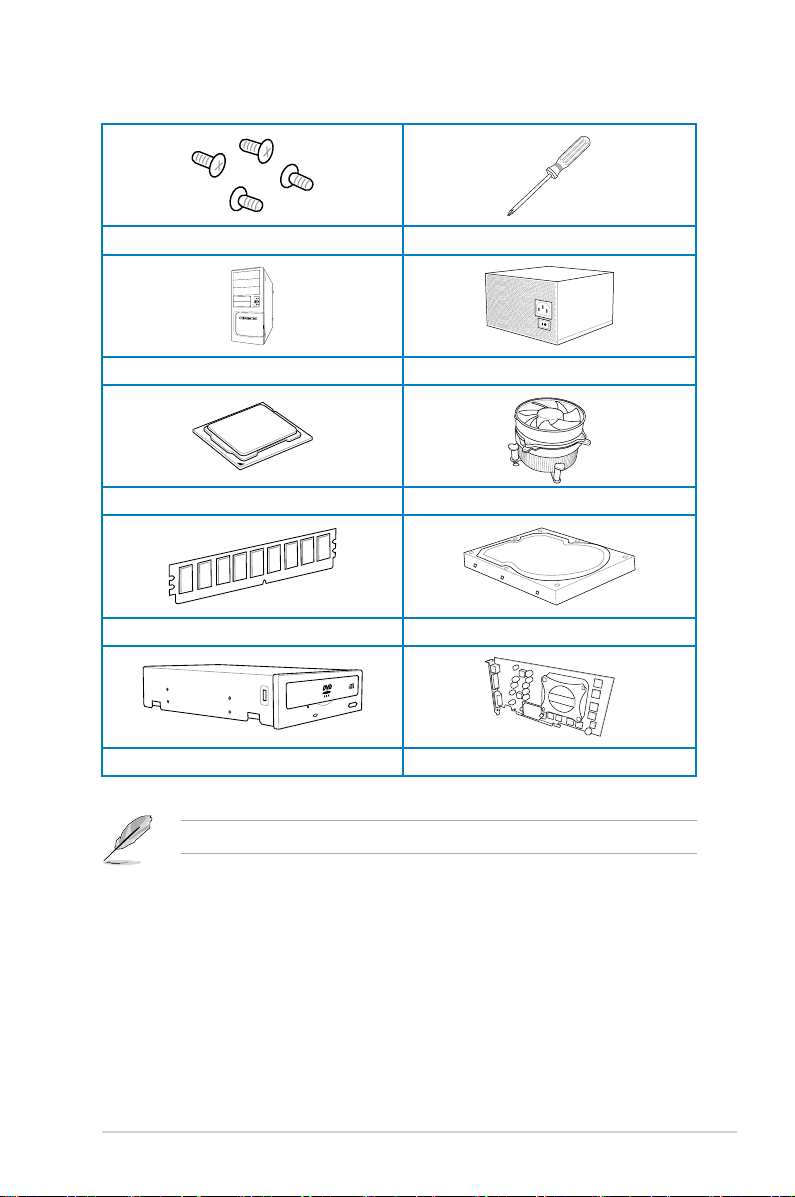
xiii Installation tools and components 1 bag of screws Philips (cross) screwdriver PC chassis Power supply unit Intel LGA1 155 CPU Intel LGA1 155 CPU Fan DIMM SA T A hard disk drive SA T A optical disc drive (optional) Graphics card (optional) The tools and components in the table above are not included in the motherboard package.[…]
-
Страница 14
xiv[…]
-
Страница 15
ASUS P8Z77-V LX2 1-1 Product introduction 1 1.1 Special features 1.1.1 Product highlights LGA1 155 socket for Intel ® 2nd/3rd Generation Core™ i7 / Core™ i5 / Core™ i3, Pentium ® , and Celeron ® Processors This motherboard supports Intel 2nd/3rd generation Core™ i7/i5/i3, Pentium, and Celeron processors in the LGA1 155 package. It provid[…]
-
Страница 16
1-2 Chapter 1: Product introduction Chapter 1 Chapter 1 Chapter 1 Chapter 1 Intel ® Smart Response T echnology Intel ® Smart Response T echnology , an important part of Green ASUS eco-friendly computing, reduces load and wait time, eliminates unecessary hard drive spin thus lowering power usage, and uses an installed SSD (requires 18.6 GB availab[…]
-
Страница 17
ASUS P8Z77-V LX2 1-3 Chapter 1 Chapter 1 Chapter 1 Chapter 1 8-channel high denition audio The onboard 8-channel HD audio (High Denition Audio, previously codenamed Azalia) CODEC enables high-quality 192KHz/24-bit audio output and jack-detect feature that automatically detects and identies what types of peripherals are plugged into the aud[…]
-
Страница 18
1-4 Chapter 1: Product introduction Chapter 1 Chapter 1 Chapter 1 Chapter 1 1.2 Motherboard overview 1.2.1 Before you proceed T ake note of the following precautions before you install motherboard components or change any motherboard settings. • Unplug the power cord from the wall socket before touching any component. • Before handling componen[…]
-
Страница 19
ASUS P8Z77-V LX2 1-5 Chapter 1 Chapter 1 Chapter 1 Chapter 1 1.2.2 Motherboard layout Refer to 2.2.1 Rear I/O connection for more information about rear panel connectors. P8Z77-V LX2 PCIEX16_1 PCIEX16_2 PCIEX1_2 PCIEX1_1 PCI1 PCI2 USB78 USB56 USB3_34 SPDIF_OUT AAFP CPU_FAN CHA_FAN2 CHA_FAN1 PWR_FAN Lithium Cell CMOS Power Super I/O ASM 1442 DIGI +V[…]
-
Страница 20
1-6 Chapter 1: Product introduction Chapter 1 Chapter 1 Chapter 1 Chapter 1 Layout contents Connectors/Jumpers/Slots/LED Page 1. CPU, Chassis and power fan connectors (4-pin CPU_F AN, 4-pin CHA_F AN1/2, 3-pin PWR_F AN) 1-23 2. EA TX power connectors (24-pin EA TXPWR, 4-pin EA TX12V) 1-26 3. Intel ® CPU socket 4. DDR3 DIMM sockets 1-7 5. USB 3.0 co[…]
-
Страница 21
ASUS P8Z77-V LX2 1-7 Chapter 1 Chapter 1 Chapter 1 Chapter 1 1.2.3 System memory This motherboard comes with four Double Data Rate 3 (DDR3) Dual Inline Memory Modules (DIMM) sockets. A DDR3 module has the same physical dimensions as a DDR2 DIMM but is notched differently to prevent installation on a DDR2 DIMM socket. DDR3 modules are developed for […]
-
Страница 22
1-8 Chapter 1: Product introduction Chapter 1 Chapter 1 Chapter 1 Chapter 1 Memory congurations Y ou may install 1GB, 2GB, 4GB and 8GB unbuffered non-ECC DDR3 DIMMs into the DIMM sockets. • The default memory operation frequency is dependent on its Serial Presence Detect (SPD), which is the standard way of accessing information from a memory m[…]
-
Страница 23
ASUS P8Z77-V LX2 1-9 Chapter 1 Chapter 1 Chapter 1 Chapter 1 V endors Part No. Size SS/DS Chip Brand Chip NO. Timing V oltage DIMM socket support (Optional) 1 DIMM 2 DIMMs 4 DIMMs Transcend TX2400KLU-4GK (381850)(XMP) 4GB(2x 2GB) SS — — 9 1.65V • • P8Z77-V LX2 Motherboard Qualied V endors Lists (QVL) DDR3 2400MHz capability * The 2400MHz mem[…]
-
Страница 24
1-10 Chapter 1: Product introduction Chapter 1 Chapter 1 Chapter 1 Chapter 1 P8Z77-V LX2 Motherboard Qualified V endors Lists (QVL) DDR3 2000MHz capability V endors Part No. Size SS/ DS Chip Brand Chip NO. Timing Voltage DIMM socket support (Optional) 1 DIMM 2 DIMMs 4 DIMMs Apacer 78.AAGD5.9KD(XMP) 6GB(3 x 2GB) DS — — 9-9-9-27 1.65V • • • COR[…]
-
Страница 25
ASUS P8Z77-V LX2 1-1 1 Chapter 1 Chapter 1 Chapter 1 Chapter 1 P8Z77-V LX2 Motherboard Qualified V endors Lists (QVL) DDR3 1600MHz capability V endors Part No. Size SS/ DS Chip Brand Chip NO. Timing Voltage DIMM socket support (Optional) 1 DIMM 2 DIMMs 4 DIMMs A-DA TA AM2U16BC2P1 2GB SS A-DA TA 3CCD-150 9A EL1 126T — — • • • A-DA TA AD31600E0[…]
-
Страница 26
1-12 Chapter 1: Product introduction Chapter 1 Chapter 1 Chapter 1 Chapter 1 V endors Part No. Size SS/ DS Chip Brand Chip NO. Timing Voltage DIMM socket support (Optional) 1 DIMM 2 DIMMs 4 DIMMs KINGSTON KHX1600C9D3T1BK3/ 12GX(XMP) 12GB(3x4GB) DS — — 9-9-9-27 1.65V • • • KINGSTON KHX1600C9AD3/2G 2GB DS — — — 1.65V • • • KINGSTON KVR160[…]
-
Страница 27
ASUS P8Z77-V LX2 1-13 Chapter 1 Chapter 1 Chapter 1 Chapter 1 V endors Part No. Size SS/ DS Chip Brand Chip NO. Timing V oltage DIMM socket support (Optional) 1 DIMM 2 DIMMs 4 DIMMs Crucial CT12864BA1339.8FF 1GB SS Micron 9FF22D9KPT 9 — • • • Crucial CT25664BA1339.16FF 2GB DS Micron 9KF27D9KPT 9 — • • • Crucial BL25664BN13 37.16FF (XMP)[…]
-
Страница 28
1-14 Chapter 1: Product introduction Chapter 1 Chapter 1 Chapter 1 Chapter 1 V endors Part No. Size SS/ DS Chip Brand Chip NO. Timing V oltage DIMM socket support (Optional) 1 DIMM 2 DIMMs 4 DIMMs Micron MT8JTF25664AZ- 1G4D1 2GB SS Micron OJD12D9LGK — — • • • Micron MT8JTF25664AZ- 1G4M1 2GB SS MICRON IJM22 D9PFJ — — • • • Micron MT16JTF[…]
-
Страница 29
ASUS P8Z77-V LX2 1-15 Chapter 1 Chapter 1 Chapter 1 Chapter 1 V endors Part No. Size SS/ DS Chip Brand Chip NO. Timing V oltage DIMM socket support (Optional) 1 DIMM 2 DIMMs 4 DIMMs Micron MT8JTF25664AZ- 1G4D1 2GB SS Micron OJD12D9LGK — — • • • Micron MT8JTF25664AZ- 1G4M1 2GB SS MICRON IJM22 D9PFJ — — • • • Micron MT16JTF25664AZ- 1G4F1 […]
-
Страница 30
1-16 Chapter 1: Product introduction Chapter 1 Chapter 1 Chapter 1 Chapter 1 1.2.4 Expansion slots Unplug the power cord before adding or removing expansion cards. Failure to do so may cause you physical injury and damage motherboard components. Slot No. Slot Description 1 PCIe 2.0 x1_1 slot 2 PCIe 3.0/2.0 x16_1 slot [blue] (at 16x mode) 3 PCIe 2.0[…]
-
Страница 31
ASUS P8Z77-V LX2 1-17 Chapter 1 Chapter 1 Chapter 1 Chapter 1 IRQ assignments for this motherboard A B C D E F G H IGD shared – – – – – – – Audio Controller – – – – – – shared EHCI Controller – – – – – – shared XHCI Controller shared – – – – – – SA T A Controller – – – shared – – – PCIEX[…]
-
Страница 32
1-18 Chapter 1: Product introduction Chapter 1 Chapter 1 Chapter 1 Chapter 1 T o erase the RTC RAM: 1. Turn OFF the computer and unplug the power cord. 2. Move the jumper cap from pins 1-2 (default) to pins 2-3. Keep the cap on pins 2-3 for about 5~10 seconds, then move the cap back to pins 1-2. 3. Plug the power cord and turn ON the computer . 4. […]
-
Страница 33
ASUS P8Z77-V LX2 1-19 Chapter 1 Chapter 1 Chapter 1 Chapter 1 1.2.6 Onboard LED 1. Standby Power LED The motherboard comes with a standby power LED that lights up to indicate that the system is ON, in sleep mode, or in soft-off mode. This is a reminder that you should shut down the system and unplug the power cable before removing or plugging in an[…]
-
Страница 34
1-20 Chapter 1: Product introduction Chapter 1 Chapter 1 Chapter 1 Chapter 1 • These connectors are set to [AHCI Mode] by default. If you intend to create a Serial A T A RAID set using these connectors, set the SA T A Mode item in the BIOS to [RAID Mode]. Refer to section 3.5.3 SA T A Conguration for details. • Before creating a RAID set, re[…]
-
Страница 35
ASUS P8Z77-V LX2 1-21 Chapter 1 Chapter 1 Chapter 1 Chapter 1 3. USB 2.0 connectors (10-1 pin USB56, USB78) These connectors are for USB 2.0 ports. Connect the USB module cable to any of these connectors, then install the module to a slot opening at the back of the system chassis. These USB connectors comply with USB 2.0 specication that support[…]
-
Страница 36
1-22 Chapter 1: Product introduction Chapter 1 Chapter 1 Chapter 1 Chapter 1 4. Front panel audio connector (10-1 pin AAFP) This connector is for a chassis-mounted front panel audio I/O module that supports either HD Audio or legacy AC`97 audio standard. Connect one end of the front panel audio I/O module cable to this connector . • We recommend […]
-
Страница 37
ASUS P8Z77-V LX2 1-23 Chapter 1 Chapter 1 Chapter 1 Chapter 1 6. CPU, chassis, and power fan connectors (4-pin CPU_F AN, 4-pin CHA_F AN1/2; 3-pin PWR_FAN) Connect the fan cables to the fan connectors on the motherboard, ensuring that the black wire of each cable matches the ground pin of the connector . Do not forget to connect the fan cables to th[…]
-
Страница 38
1-24 Chapter 1: Product introduction Chapter 1 Chapter 1 Chapter 1 Chapter 1 7. USB 3.0 connector (20-1 pin USB3_34) These connectors are for the additional USB 3.0 ports, and complies with the USB 3.0 specicaton that supports up to 480 MBps connection speed. If the USB 3.0 front panel cable is available from your system chassis, with this USB 3[…]
-
Страница 39
ASUS P8Z77-V LX2 1-25 Chapter 1 Chapter 1 Chapter 1 Chapter 1 8. Intel ® Z77 Serial A T A 3.0 Gb/s connectors (7-pin SA T A3G_1–4 [blue]) These connectors connect to Serial A T A 3.0 Gb/s hard disk drives and optical disc drives via Serial A T A 3.0 Gb/s signal cables. If you installed Serial A T A hard disk drives, you can create a RAID 0, 1, 5[…]
-
Страница 40
1-26 Chapter 1: Product introduction Chapter 1 Chapter 1 Chapter 1 Chapter 1 9. A TX power connectors (24-pin EA TXPWR; 4-pin EA TX12V) These connectors are for A TX power supply plugs. The power supply plugs are designed to t these connectors in only one orientation. Find the proper orientation and push down rmly until the connectors complet[…]
-
Страница 41
ASUS P8Z77-V LX2 1-27 Chapter 1 Chapter 1 Chapter 1 Chapter 1 • System power LED (2-pin PLED) This 2-pin connector is for the system power LED. Connect the chassis power LED cable to this connector . The system power LED lights up when you turn on the system power , and blinks when the system is in sleep mode. • Hard disk drive activity LED (2-[…]
-
Страница 42
1-28 Chapter 1: Product introduction Chapter 1 Chapter 1 12. Speaker connector (4- pin SPEAKER) This 4-pin connector is for the chassis-mounted system warning speaker . The speaker allows you to hear system beeps and warnings. P8Z77-V LX2 P8Z77-V LX2 Speaker Out connector +5V GND GND Speaker Out SPEAKER PIN 1[…]
-
Страница 43
ASUS P8Z77-V LX2 2-1 Chapter 2 Basic Installation 2 2.1 Building your PC system 2.1.1 Motherboard installation 1 The diagrams in this section are for reference only . The motherboard layout may vary with models, but the installation steps are the same for all models. 1. Install the I/O Shield to the chassis rear I/O panel.[…]
-
Страница 44
2-2 Chapter 2: Basic installation Chapter 2 2. Place the motherboard into the chassis, ensuring that its rear I/O ports are aligned to the chassis’ rear I/O panel.[…]
-
Страница 45
ASUS P8Z77-V LX2 2-3 Chapter 2 3. Place six screws into the holes indicated by circles to secure the motherboard to the chassis. DO NOT overtighten the screws! Doing so can damage the motherboard. P8Z77-V LX2[…]
-
Страница 46
2-4 Chapter 2: Basic installation Chapter 2 2.1.2 CPU installation The LGA1 156 CPU is incompatible with the LGA1 155 socket. DO NOT install a LGA1 156 CPU on the LGA1 155 socket. A B 1 2[…]
-
Страница 47
ASUS P8Z77-V LX2 2-5 Chapter 2 A B C 4 5 3[…]
-
Страница 48
2-6 Chapter 2: Basic installation Chapter 2 2.1.3 CPU heatsink and fan assembly installation Apply the Thermal Interface Material to the CPU heatsink and CPU before you install the heatsink and fan if necessary . T o install the CPU heatsink and fan assembly 2 B B A A 1 3 4[…]
-
Страница 49
ASUS P8Z77-V LX2 2-7 Chapter 2 T o uninstall the CPU heatsink and fan assembly 2 A B B A 1[…]
-
Страница 50
2-8 Chapter 2: Basic installation Chapter 2 1 2 3 T o remove a DIMM 2.1.4 DIMM installation B A A[…]
-
Страница 51
ASUS P8Z77-V LX2 2-9 Chapter 2 2.1.5 A TX Power connection 1 2[…]
-
Страница 52
2-10 Chapter 2: Basic installation Chapter 2 2.1.6 SA T A device connection 2 OR 1[…]
-
Страница 53
ASUS P8Z77-V LX2 2-1 1 Chapter 2 2.1.7 Expansion Card installation T o install PCIe x16 cards T o install PCIe x1 cards T o install PCI cards[…]
-
Страница 54
2-12 Chapter 2: Basic installation Chapter 2 2.2 Motherboard rear and audio connections 2.2.1 Rear I/O connection 3 7 2 1 8 9 4 5 6 Rear panel connectors 1. PS/2 Mouse port 6. USB 3.0 ports 1 and 2 2. Video Graphics Adapter (VGA) port 7. USB 2.0 ports 3 and 4 3. Intel ® LAN (RJ-45) port* 8. HDMI port 4. Audio I/O ports** 9. PS/2 Keyboard port 5. U[…]
-
Страница 55
ASUS P8Z77-V LX2 2-13 Chapter 2 * LAN ports LED indications Activity Link LED Speed LED Status Description Status Description OFF No link OFF 10 Mbps connection ORANGE Linked ORANGE 100 Mbps connection BLINKING Data activity GREEN 1 Gbps connection SPEED LED ACT/LINK LED LAN port Ports Headset 2-channel 4-channel 6-channel 8-channel Light Blue Line[…]
-
Страница 56
2-14 Chapter 2: Basic installation Chapter 2 Connect to Headphone and Mic Connect to Stereo Speakers Connect to 2.1 channel Speakers 2.2.2 Audio I/O connections Audio I/O ports[…]
-
Страница 57
ASUS P8Z77-V LX2 2-15 Chapter 2 Connect to 4.1 channel Speakers Connect to 5.1 channel Speakers Connect to 7.1 channel Speakers[…]
-
Страница 58
2-16 Chapter 2: Basic installation Chapter 2 2.3 Starting up for the rst time 1. After making all the connections, replace the system case cover. 2. Ensure that all switches are off. 3. Connect the power cord to the power connector at the back of the system chassis. 4. Connect the power cord to a power outlet that is equipped with a surge protec[…]
-
Страница 59
ASUS P8Z77-V LX2 3-1 Chapter 3 BIOS setup 3 3.1 Knowing BIOS The new ASUS UEFI BIOS is a Unied Extensible Interface that complies with UEFI architecture, offering a user-friendly interface that goes beyond the traditional keyboard- only BIOS controls to enable a more exible and convenient mouse input. Y ou can easily navigate the new UEFI BIO[…]
-
Страница 60
3-2 Chapter 3: BIOS setup Chapter 3 3.2 BIOS setup program Use the BIOS Setup to update the BIOS or congure its parameters. The BIOS screen include navigation keys and brief onscreen help to guide you in using the BIOS Setup program. Entering BIOS at startup T o enter BIOS Setup at startup: • Press <Delete> during the Power-On Self T est[…]
-
Страница 61
ASUS P8Z77-V LX2 3-3 Chapter 3 3.2.1 EZ Mode By default, the EZ Mode screen appears when you enter the BIOS setup program. The EZ Mode provides you an overview of the basic system information, and allows you to select the display language, system performance mode and boot device priority . T o access the Advanced Mode, click Exit/Advanced Mode, the[…]
-
Страница 62
3-4 Chapter 3: BIOS setup Chapter 3 3.2.2 Advanced Mode The Advanced Mode provides advanced options for experienced end-users to congure the BIOS settings. The gure below shows an example of the Advanced Mode. Refer to the following sections for the detailed congurations. T o access the Advanced Mode, click Exit , then select Advanced Mode[…]
-
Страница 63
ASUS P8Z77-V LX2 3-5 Chapter 3 Menu items The highlighted item on the menu bar displays the specic items for that menu. For example, selecting Main shows the Main menu items. The other items (Ai T weaker, Advanced, Monitor , Boot, T ool, and Exit) on the menu bar have their respective menu items. Back button This button appears when entering a s[…]
-
Страница 64
3-6 Chapter 3: BIOS setup Chapter 3 3.3 Main menu The Main menu screen appears when you enter the Advanced Mode of the BIOS Setup program. The Main menu provides you an overview of the basic system information, and allows you to set the system date, time, language, and security settings. Security The Security menu items allow you to change the syst[…]
-
Страница 65
ASUS P8Z77-V LX2 3-7 Chapter 3 Administrator Password If you have set an administrator password, we recommend that you enter the administrator password for accessing the system. Otherwise, you might be able to see or change only selected elds in the BIOS setup program. T o set an administrator password: 1. Select the Administrator Password item […]
-
Страница 66
3-8 Chapter 3: BIOS setup Chapter 3 T o change a user password: 1. Select the User Password item and press <Enter>. 2. From the Enter Current Password box, key in the current password, then press <Enter>. 3. From the Create New Password box, key in a new password, then press <Enter>. 4. Conrm the password when prompted. T o cle[…]
-
Страница 67
ASUS P8Z77-V LX2 3-9 Chapter 3 Ai Overclock T uner [Auto] Allows you to select the CPU overclocking options to achieve the desired CPU internal frequency . Select any of these preset overclocking conguration options: [Auto] Loads the optimal settings for the system. [Manual] Allows you to individually set overclocking parameters. The following i[…]
-
Страница 68
3-10 Chapter 3: BIOS setup Chapter 3 Internal PLL Overvoltage [Auto] Allows you to set the Internal PLL Overvoltage. Conguration options: [Auto] [Enabled] [Disabled]. CPU bus speed : DRAM speed ratio mode [Auto] Allows you to set the CPU bus speed to DRAM speed ratio mode. [Auto] DRAM speed is set to the optimized settings. [100:133] The CPU bus[…]
-
Страница 69
ASUS P8Z77-V LX2 3-1 1 Chapter 3 CPU Power Management The sub-items in this menu allow you to set the CPU ratio and features. CPU Ratio [Auto] Allows you to manually adjust the maximum non-turbo CPU ratio. Use <+> and <-> keys to adjust the value. The valid value ranges vary according to your CPU model. Enhanced Intel SpeedStep T echnol[…]
-
Страница 70
3-12 Chapter 3: BIOS setup Chapter 3 DIGI+ VRM CPU Load-Line Calibration [Auto] Load-line is dened by Intel VRM spec and affects CPU voltage. The CPU working voltage will decrease proportionally to CPU loading. Higher value gets a higher voltage and better overclocking performance, but increases the CPU and VRM thermal. This item allows you to a[…]
-
Страница 71
ASUS P8Z77-V LX2 3-13 Chapter 3 iGPU Load-line Calibration [Auto] Allows you to set the iGPU Load-line Calibration. Conguration options: [Auto] [Regular] [High] [Extreme] The actual performance boost may vary depending on your CPU conguration. iGPU Current Capability [100%] Allows you to set the iGPU Current Capability . Conguration option[…]
-
Страница 72
3-14 Chapter 3: BIOS setup Chapter 3 CPU V oltage [Offset Mode] [Manual Mode] Allows you to set a xed CPU voltage. [Offset Mode] Allows you to set the Offset voltage. CPU Offset Mode Sign [+] This item appears only when you set the CPU V oltage item to [Offset Mode]. [+] T o offset the voltage by a positive value. [–] T o offset the voltage by[…]
-
Страница 73
ASUS P8Z77-V LX2 3-15 Chapter 3 DRAM V oltage [Auto] Allows you to set the DRAM voltage. The values range from 1.185V to 2.135V with a 0.005V interval. According to Intel CPU spec, DIMMs with voltage requirement over 1.65V may damage the CPU permanently . We recommend you install the DIMMs with the voltage requirement below 1.65V . • The values o[…]
-
Страница 74
3-16 Chapter 3: BIOS setup Chapter 3 3.5 Advanced menu The Advanced menu items allow you to change the settings for the CPU and other system devices. Be cautious when changing the settings of the Advanced menu items. Incorrect eld values can cause the system to malfunction. 3.5.1 CPU Conguration The items in this menu show the CPU-related inf[…]
-
Страница 75
ASUS P8Z77-V LX2 3-17 Chapter 3 Intel Adaptive Thermal Monitor [Enabled] [Enabled] Enables the overheated CPU to throttle its clock speed to cool down. [Disabled] Disables the CPU thermal monitor function. Active Processor Cores [All] Allows you to choose the number of CPU cores to activate in each processor package. Conguration options: [All] [[…]
-
Страница 76
3-18 Chapter 3: BIOS setup Chapter 3 CPU Power Management Conguration CPU Ratio [Auto] Allows you to set the ratio between the CPU Core Clock and the BCLK Frequency . Use <+> and <-> keys to adjust the ratio. The valid value ranges vary according to your CPU model. Enhanced Intel SpeedStep T echnology [Enabled] Allows you to enable o[…]
-
Страница 77
ASUS P8Z77-V LX2 3-19 Chapter 3 3.5.2 PCH Conguration High Precision Timer [Enabled] Allows you to enable or disable the High Precision Event T imer . Conguration options: [Enabled] [Disabled] Intel(R) Rapid Start T echnology Intel(R) Rapid Start T echnology [Disabled] Allows you to enable or disable the Intel(R) Rapid Start T echnology .Con?[…]
-
Страница 78
3-20 Chapter 3: BIOS setup Chapter 3 SA T A Mode Selection [AHCI] Allows you to set the SA T A conguration. [IDE Mode] Set to [IDE Mode] when you want to use the Serial A T A hard disk drives as Parallel A T A physical storage devices. [AHCI Mode] Set to [AHCI Mode] when you want the SA T A hard disk drives to use the AHCI (Advanced Host Control[…]
-
Страница 79
ASUS P8Z77-V LX2 3-21 Chapter 3 Graphics Conguration Primary Display [Auto] Allows you to select a primary display from IGFX, PEG, or PCI graphic devices, or select SG for switchable GFX. Conguration options: [Auto] [IGFX] [PEG] [PCI] iGPU Memory [64M] Allows you to set the iGPU memory size. Conguration options: [32M] [64M] [96M] [128M] ~ […]
-
Страница 80
3-22 Chapter 3: BIOS setup Chapter 3 Legacy USB Support [Enabled] [Enabled] Enables the support for USB devices on legacy operating systems (OS). [Disabled] The USB devices can be used only for the BIOS setup program. [Auto] Allows the system to detect the presence of USB devices at sta rtup. If detected, the USB controller legacy mode is enabled. […]
-
Страница 81
ASUS P8Z77-V LX2 3-23 Chapter 3 HD Audio Controller [Enabled] [Enabled] Enables the High Denition Audio Controller. [Disabled] Disables the controller. The following two items appear only when you set the HD Audio Controller item to [Enabled]. Front Panel T ype [HD] Allows you to set the front panel audio connector (AAFP) mode to legacy AC’97 […]
-
Страница 82
3-24 Chapter 3: BIOS setup Chapter 3 Restore AC Power Loss [Power Off] [Power On] The system goes into on state after an AC power loss. [Power Off] The system goes into off state after an AC power loss. [Last State] The system goes into either off or on state, whatever the system state was before the AC power loss. Power On By PS/2 Keyboard [Disabl[…]
-
Страница 83
ASUS P8Z77-V LX2 3-25 Chapter 3 CPU T emperature / MB T emperature [xxxºC/xxxºF] The onboard hardware monitor automatically detects and displays the CPU and motherboard temperatures. Select Ignore if you do not wish to display the detected temperatures. CPU Fan Speed [xxxx RPM] or [Ignore] / [N/A] Chassis Fan 1/2 Speed [xxxx RPM] or [Ignore] / [N[…]
-
Страница 84
3-26 Chapter 3: BIOS setup Chapter 3 CPU Q-Fan Control [Enabled] [Disabled] Disables the CPU Q-Fan control feature. [Enabled] Enables the CPU Q-Fan control feature. CPU Fan Speed Low Limit [600 RPM] This item appears only when you enable the CPU Q-Fan Control feature and allows you to disable or set the CPU fan warning speed. Conguration options[…]
-
Страница 85
ASUS P8Z77-V LX2 3-27 Chapter 3 Chassis Q-Fan Control [Enabled] [Disabled] Disables the Chassis Q-Fan control feature. [Enabled] Enables the Chassis Q-Fan control feature. Chassis Fan Speed Low Limit [600 RPM] This item appears only when you enable the Chassis Q-Fan Control feature and allows you to disable or set the chassis fan warning speed. Con[…]
-
Страница 86
3-28 Chapter 3: BIOS setup Chapter 3 3.7 Boot menu The Boot menu items allow you to change the system boot options. Bootup NumLock State [On] [On] Sets the power-on state of the NumLock to [On]. [Off] Sets the power-on state of the NumLock to [Off]. Full Screen Logo [Enabled] [Enabled] Enables the full screen logo display feature. [Disabled] Disabl[…]
-
Страница 87
ASUS P8Z77-V LX2 3-29 Chapter 3 USB Support [Partial Initial] [Disabled] All USB devices will not be available until after OS boot. [Full Initial] All USB devices will be available in OS and during POST . [Partial Initial] Specic USB port/device will not be available before OS boot. PS2 Keyboard and Mouse Support [Enabled] [Auto] Automatic con?[…]
-
Страница 88
3-30 Chapter 3: BIOS setup Chapter 3 Boot Option Priorities These items specify the boot device priority sequence from the available devices. The number of device items that appears on the screen depends on the number of devices installed in the system. • T o select the boot device during system startup, press <F8> when ASUS Logo appears. ?[…]
-
Страница 89
ASUS P8Z77-V LX2 3-31 Chapter 3 3.8 T ools menu The T ools menu items allow you to congure options for special functions. Select an item then press <Enter> to display the submenu. ASUS EZ Flash 2 utility Allows you to run ASUS EZ Flash 2. When you press <Enter>, a conrmation message appears. Use the left/right arrow key to select […]
-
Страница 90
3-32 Chapter 3: BIOS setup Chapter 3 3.9 Exit menu The Exit menu items allow you to load the optimal default values for the BIOS items, and save or discard your changes to the BIOS items. Y ou can access the EZ Mode from the Exit menu. Load Optimized Defaults This option allows you to load the default values for each of the parameters on the Setup […]
-
Страница 91
ASUS P8Z77-V LX2 3-33 Chapter 3 3.10 Updating BIOS The ASUS website publishes the latest BIOS versions to provide enhancements on system stability , compatibility , or performance. However , BIOS updating is potentially risky . If there is no problem using the current version of BIOS, DO NOT manually update the BIOS . Inappropriate BIOS updating ma[…]
-
Страница 92
3-34 Chapter 3: BIOS setup Chapter 3 Updating the BIOS through the Internet T o update the BIOS through the Internet: 1. From the ASUS Update screen, select Update BIOS from Internet , and then click Next . 2. Select the ASUS FTP site nearest you to avoid network trafc. If you want to enable the BIOS downgradable function and auto BIOS backup fu[…]
-
Страница 93
ASUS P8Z77-V LX2 3-35 Chapter 3 • The screenshots in this section are for reference only . The actual BIOS information vary by models. • Refer to the software manual in the support DVD or visit the ASUS website at www. asus.com for detailed software conguration. Updating the BIOS through a BIOS le T o update the BIOS through a BIOS le:[…]
-
Страница 94
3-36 Chapter 3: BIOS setup Chapter 3 3.10.2 ASUS EZ Flash 2 utility The ASUS EZ Flash 2 feature allows you to update the BIOS without having to use a bootable oppy disk or an OS-based utility . Before you start using this utility , download the latest BIOS from the ASUS website at www .asus.com. T o update the BIOS using EZ Flash 2: 1. Insert th[…]
-
Страница 95
ASUS P8Z77-V LX2 3-37 Chapter 3 • This function can support devices such as a USB ash disk with F A T 32/16 format and single partition only . • DO NOT shut down or reset the system while updating the BIOS to prevent system boot failure! Ensure to load the BIOS default settings to ensure system compatibility and stability . Select the Load O[…]
-
Страница 96
3-38 Chapter 3: BIOS setup Chapter 3 3.10.4 ASUS BIOS Updater The ASUS BIOS Updater allows you to update BIOS in DOS environment. This utility also allows you to copy the current BIOS le that you can use as a backup when the BIOS fails or gets corrupted during the updating process. The succeeding utility screens are for reference only . The actu[…]
-
Страница 97
ASUS P8Z77-V LX2 3-39 Chapter 3 Welcome to FreeDOS (http://www.freedos.org)! C:>d: D:> 3. When the Make Disk menu appears, select the FreeDOS command prompt item by pressing the item number . 4. At the FreeDOS prompt, type d: and press <Enter> to switch the disk from Drive C (optical drive) to Drive D (USB ash drive). Updating the […]
-
Страница 98
3-40 Chapter 3: BIOS setup Chapter 3 4. Select Y es and press <Enter>. When BIOS update is done, press <ESC> to exit BIOS Updater . Restart your computer . DO NOT shut down or reset the system while updating the BIOS to prevent system boot failure! • For BIOS Updater version 1.04 or later , the utility automatically exits to the DOS p[…]
-
Страница 99
ASUS P8Z77-V LX2 4-1 Chapter 4 Software support 4 If Autorun is NOT enabled in your computer , browse the contents of the support DVD to locate the le ASSETUP .EXE from the BIN folder . Double-click the ASSETUP .EXE to run the DVD. 4.1 Installing an operating system • This motherboard supports Windows ® 7 / 64-bit 7 operating systems (OS). T […]
-
Страница 100
4-2 Chapter 4: Software support Chapter 4 4.2.2 Obtaining the software manuals The software manuals are included in the support DVD. Follow the instructions below to get the necessary software manuals. The software manual les are in Portable Document Format (PDF). Install the Adobe® Acrobat® Reader from the Utilities menu before opening the ?[…]
-
Страница 101
ASUS P8Z77-V LX2 4-3 Chapter 4 4.3 Software information Most of the applications in the support DVD have wizards that will conveniently guide you through the installation. View the online help or readme le that came with the software application for more information. 4.3.1 AI Suite II AI Suite II is an all-in-one interface that integrates severa[…]
-
Страница 102
4-4 Chapter 4: Software support Chapter 4 4.3.2 T urboV EVO ASUS T urboV EVO includes T urboV that allows you to manually adjust the CPU frequency and related voltages such as Auto T uning that offers automatic and easy overclocking and system boost performance. T o launch AI Suite II, click T ool > T urboV EVO on the AI Suite II main menu bar .[…]
-
Страница 103
ASUS P8Z77-V LX2 4-5 Chapter 4 Using Advanced Mode Click on the Advanced Mode tab to adjust the advanced voltage settings. Advanced mode Current values T arget values V oltage Adjustment bars Click to restore all startup settings Undoes all the changes Applies all the changes immediately[…]
-
Страница 104
4-6 Chapter 4: Software support Chapter 4 CPU Ratio Allows you to manually adjust the CPU ratio. • The rst time you use CPU Ratio, go to AI T weaker > CPU Power Management in BIOS and set the T urbo Ratio item to [Maximum T urbo Ratio setting in OS] . • Set the CPU Ratio Setting item in BIOS to [Auto] before using the CPU Ratio function i[…]
-
Страница 105
ASUS P8Z77-V LX2 4-7 Chapter 4 Auto T uning ASUS T urboV EVO provides you with a Fast T uning mode. • The overclocking result varies with the CPU model and the system conguration. • We recommend that you set up a better thermal environment to prevent overheating from damaging the motherboard. Fast T uning : fast CPU/iGPU overclocking Using F[…]
-
Страница 106
4-8 Chapter 4: Software support Chapter 4 3. After the system restarts, a message appears indicating that auto-tuning is successful. Click OK to exit.[…]
-
Страница 107
ASUS P8Z77-V LX2 4-9 Chapter 4 4.3.3 DIGI+ VRM ASUS DIGI+ VRM allows you to adjust VRM voltage and frequency modulation to enhance reliability and stability . It also provides the highest power efciency while generating less heat to prolong component lifespan and minimize power loss. After installing AI Suite II from the motherboard support DVD,[…]
-
Страница 108
4-10 Chapter 4: Software support Chapter 4 • The actual performance boost may vary depending on your CPU specication. • Do not remove the thermal module. The thermal conditions should be monitored. Refer to the software manual in the support DVD or visit the ASUS website at www .asus.com for detailed software conguration. Items Function d[…]
-
Страница 109
ASUS P8Z77-V LX2 4-1 1 Chapter 4 • Select From EPU Installation to show the CO2 that has been reduced since you installed EPU. • *Select From the Last Reset to show the total CO2 that has been reduced since you click the Clear button . • Refer to the software manual in the support DVD or visit the ASUS website at www. asus.com for detailed so[…]
-
Страница 110
4-12 Chapter 4: Software support Chapter 4 Refer to the software manual in the support DVD or visit the ASUS website at www .asus.com for detailed software conguration. 4.3.5 F AN Xpert+ Fan Xpert intelligently allows you to adjust both the CPU and chassis fan speeds according to different ambient temperatures caused by different climate conditi[…]
-
Страница 111
ASUS P8Z77-V LX2 4-13 Chapter 4 4.3.6 Probe II Probe II is a utility that monitors the computer’s vital components, and detects and alerts you of any problem with these components. Probe II senses fan rotations, CPU temperature, and system voltages, among others. With this utility , you are assured that your computer is always at a healthy operat[…]
-
Страница 112
4-14 Chapter 4: Software support Chapter 4 4.3.7 Sensor Recorder Sensor Recorder monitors the changes in the system voltage, temperature, and fan speed on a timeline. The History Record function allows you to designate specic time spans on record to keep track of the three system statuses for certain purposes. Launching Sensor Recorder T o launc[…]
-
Страница 113
ASUS P8Z77-V LX2 4-15 Chapter 4 Click on Monitor > Sensor on the AI Suite II main menu bar and a highlight of the system statuses will appear on the right panel. 4. T o track the recorded contents, set T ype/ Date/ Select display items to display the history details.[…]
-
Страница 114
4-16 Chapter 4: Software support Chapter 4 4.3.8 USB 3.0 Boost ASUS USB 3.0 Boost technology supports UASP (USB Attached SCSI Protocol) and automatically increases a USB 3.0 device’s transfer speed up to 170%. Launching USB 3.0 Boost T o launch USB 3.0 Boost, click T ool > USB 3.0 Boost on the AI Suite II main menu bar . Conguring USB 3.0 B[…]
-
Страница 115
ASUS P8Z77-V LX2 4-17 Chapter 4 4.3.9 Ai Charger Ai Charger is a unique software that allows you to quickly charge your Apple devices such as the iPod, iPhone, and iPad on your ASUS computer’s USB 2.0 / USB 3.0 port. • There is no settings screen for the Ai Charger. After installation on your computer, the Ai Charger icon will appear on the Win[…]
-
Страница 116
4-18 Chapter 4: Software support Chapter 4 4.3.10 Network iControl • Ensure to install the LAN drivers before using this function. • Network iControl is only supported under Windows 7 and can only support the onboard LAN. ASUS Network iControl, a one-stop setup network control center that gives you the EZ Start, Quick Connection, and EZ Prol[…]
-
Страница 117
ASUS P8Z77-V LX2 4-19 Chapter 4 Using Quick Connection Configuring the PPPoE connection settings Before enabling the Network iControl’s Quick Connection functions, you must congure the PPPoE connection settings T o congure the PPPoE settings: 1. Right-click in the taskbar , and select Open Network and Sharing Center . 2. Right-click the PPP[…]
-
Страница 118
4-20 Chapter 4: Software support Chapter 4 Conguring the Quick Connection T o congure the auto-PPPoE connection: Click the Quick Connection tab. T ick Automatically connect online anytime option, then select the connection name in the Connection Name dropdown box. Click Apply to enable PPPoE automatic network connection. Y ou can also enable […]
-
Страница 119
ASUS P8Z77-V LX2 4-21 Chapter 4 4.3.1 1 ASUS Update ASUS Update is a utility that allows you to manage, save, and update the motherboard BIOS in Windows ® environment. Launching ASUS Update T o launch ASUS Update, click Update > ASUS Update on the AI Suite II main menu bar . Usi ng ASUS Update Select any of these options to update the BIOS: •[…]
-
Страница 120
4-22 Chapter 4: Software support Chapter 4 4.3.12 MyLogo2 MyLogo2 allows you to customize the boot logo, which is the image that appears on the screen during the Power On Self T ests (POST). Launching ASUS Update T o launch MyLogo2, click Update > MyLogo on the AI Suite II main menu bar. Using MyLogo Select the option that you want to use to upd[…]
-
Страница 121
ASUS P8Z77-V LX2 4-23 Chapter 4 5. Click Flash to update the boot logo. 6. When prompted, click Y es to reboot the system. Y ou will see the new boot logo the next time you start up the system. Ensure to enable the Full Screen Logo in BIOS to use this feature. 4.3.13 Audio congurations The Realtek ® audio CODEC provides 8-channel audio capabili[…]
-
Страница 122
4-24 Chapter 4: Software support Chapter 4 Control settings window Conguration options Information button Exit button Minimize button B. Realtek HD Audio Manager for Windows ® XP • Refer to the software manual in the support DVD or visit the ASUS website at www. asus.com for detailed software conguration. • Due to Intel ® Z77 platform d[…]
-
Страница 123
ASUS P8Z77-V LX2 5-1 Chapter 5 RAID support 5 5.1 RAID congurations The motherboard supports the following SA T A RAID solutions: • Intel ® Rapid Storage T echnology with RAID 0, RAID 1, RAID 10 and RAID 5 support. • Y ou must install Windows ® XP Service Pack 3 or later versions before using Serial A T A hard disk drives. The Serial A T A[…]
-
Страница 124
5-2 Chapter 5: RAID congurations Chapter 5 5.1.2 Installing Serial A T A hard disks The motherboard supports Serial A T A hard disk drives. For optimal performance, install identical drives of the same model and capacity when creating a disk array . T o install the SA T A hard disks for a RAID conguration: 1. Install the SA T A hard disks int[…]
-
Страница 125
ASUS P8Z77-V LX2 5-3 Chapter 5 5.1.4 Intel ® Rapid Storage T echnology Option ROM utility T o enter the Intel ® Rapid Storage T echnology Option ROM utility: 1. Turn on the system. 2. During POST , press <Ctrl> + <I> to display the utility main menu. The navigation keys at the bottom of the screen allow you to move through the menus a[…]
-
Страница 126
5-4 Chapter 5: RAID congurations Chapter 5 Creating a RAID set T o create a RAID set: 1. From the utility main menu, select 1. Create RAID V olume and press <Enter>. The following screen appears: 2. Enter a name for the RAID set and press <Enter>. 3. When the RAID Level item is selected, press the up/down arrow key to select a RAID l[…]
-
Страница 127
ASUS P8Z77-V LX2 5-5 Chapter 5 5. Use the up/down arrow key to select a drive, and then press <Space> to select. A small triangle marks the selected drive. Press <Enter> after completing your selection. 6. Use the up/down arrow key to select the stripe size for the RAID array (for RAID 0, 10 and 5 only),and then press <Enter>. The[…]
-
Страница 128
5-6 Chapter 5: RAID congurations Chapter 5 Deleting a RAID set Be cautious when deleting a RAID set. Y ou will lose all data on the hard disk drives when you delete a RAID set. T o delete a RAID set: 1. From the utility main menu, select 2. Delete RAID V olume and press <Enter>. The following screen appears: 2. Use the up/down arrow key to[…]
-
Страница 129
ASUS P8Z77-V LX2 5-7 Chapter 5 2. Press <Y> to exit or press <N> to return to the utility main menu. Exiting the Intel ® Rapid Storage T echnology Option ROM utility T o exit the utility: 1. From the utility main menu, select 5. Exit , and then press <Enter>. The following warning message appears: A re y ou s ur e yo u wa nt t o […]
-
Страница 130
5-8 Chapter 5: RAID congurations Chapter 5 5.2 Creating a RAID driver disk A oppy disk with the RAID driver is required when installing a Windows ® operating system on a hard disk drive that is included in a RAID set. • The motherboard does not provide a oppy drive connector . Y ou have to use a USB oppy disk drive when creating a SA[…]
-
Страница 131
ASUS P8Z77-V LX2 5-9 Chapter 5 5.2.3 Installing the RAID driver during Windows ® OS installation T o install the RAID driver in Windows ® XP: 1. During the OS installation, the system prompts you to press the <F6> key to install third-party SCSI or RAID driver . 2. Press <F6>, and then insert the oppy disk with RAID driver into the[…]
-
Страница 132
5-10 Chapter 5: RAID congurations Chapter 5 5.2.4 Using a USB oppy disk drive Due to OS limitation, Windows ® XP may not recognize the USB oppy disk drive when you install the RAID driver from a oppy disk during the OS installation. T o solve this issue, add the USB oppy disk drive’s V endor ID (VID) and Product ID (PID) to the ?[…]
-
Страница 133
ASUS P8Z77-V LX2 5-1 1 Chapter 5 Add the same line to both sections. The VID and PID vary with different vendors. 8. Find the [HardwareIds.scsi.iaAHCI_DesktopWorkstationServer] and [HardwareIds.scsi.iaStor_DesktopWorkstationServer] sections in the txtsetup.oem le. 9. T ype the following line to the bottom of the two sections: id = “USBVID_xxx[…]
-
Страница 134
5-12 Chapter 5: RAID congurations Chapter 5[…]
-
Страница 135
ASUS P8Z77-V LX2 6-1 Chapter 6 Intel ® technologies 6 6.1 Introduction to Intel ® 2012 Desktop responsiveness technologies This document details the overview of the installation and conguration procedures of the Intel ® 2012 Desktop responsiveness technologies. Intel ® 2012 Desktop responsiveness technologies feature the three technologies: […]
-
Страница 136
6-2 Chapter 6: Intel ® technologies Chapter 6 SSD Capacity Requirements SSD Partition Capacity Requirements System DRAM 2GB 4GB 8GB Intel ® storage combinations Intel ® Rapid Start 2GB 4GB 8GB Intel ® Smart Response 20GB 20GB 20GB Intel ® Smart Response and Intel ® Rapid Start Separate 20GB and 2GB partition (SSD size > 22GB) Separate 20GB[…]
-
Страница 137
ASUS P8Z77-V LX2 6-3 Chapter 6 6.1.2 Intel ® Smart Response T echnology Intel ® Smart Response T echnology boosts overall system performance. It uses an installed fast SSD (min. 20GB available) as a cache for frequently accessed operations, speeding up hard drive/main memory interaction. Key benets are expedited hard drive speeds, reduced load[…]
-
Страница 138
6-4 Chapter 6: Intel ® technologies Chapter 6 3. Select Disable Acceleration to disable this function, and select Change Mode to switch acceleration mode to Enhanced/ Maximized. • T o enable Intel ® Smart Response T echnology , you need at least one SSD ( 20GB) and a HDD, and only one SSD can be assigned for caching. • If you want to restore […]
-
Страница 139
ASUS P8Z77-V LX2 6-5 Chapter 6 3. Right click the New V olume that you want to shrink from, and select Shrink V olume . 4. If your SSD is not initialized and unformatted: a. Right click the disk that you want to create the partition, and select Initialize . b. Right click the unallocated volume, select New Simple V olume , and follow the remaining […]
-
Страница 140
6-6 Chapter 6: Intel ® technologies Chapter 6 6. T o launch the disk partitioning tool, click Start > Programs > Accessories > Command Prompt tool. 7. T ype diskpart and press Enter . 8. In the diskpart prompt, type list disk after DISKP ART , and press Enter . Select the disk with the unallocated volume by typing select disk x (x = disk […]
-
Страница 141
ASUS P8Z77-V LX2 6-7 Chapter 6 12. T ype set id=84 override , press Enter , and wait for the “shrinking process” until the Disk Management utility identies a new partition called Hibernation Partition . 13. Reboot the system after creating the partition. The partition for Intel ® Rapid Start T echnology is incomplete if the computer is not […]
-
Страница 142
6-8 Chapter 6: Intel ® technologies Chapter 6 Recovering the partition This procedure allows you to delete the Intel ® Rapid Start T echnology from your system, and recover the partition you made for the Intel Rapid ® Start T echnology installation. 1. Run the Command Prompt tool. 2. T ype diskpart and press Enter . 3. At the diskpart prompt, ty[…]
-
Страница 143
ASUS P8Z77-V LX2 6-9 Chapter 6 5. T ype list partition , press Enter , and select the partition where the Intel ® Rapid Start T echnology is installed by typing select partition x (x = number), and press Enter . 6. T ype delete partition override , and press Enter . The diskpart utility deletes the selected partition. 7. In the desktop, click Star[…]
-
Страница 144
6-10 Chapter 6: Intel ® technologies Chapter 6 10. Click Next after selecting the default selected disk. 1 1. Extend volume setup is completed. Click Finish to recover the Intel ® Rapid Start T echnology partition. 12. Reboot the system after deleting the partition. 13. Go to Start > Control Panel > Programs > Programs and Features > […]
-
Страница 145
ASUS P8Z77-V LX2 6-1 1 Chapter 6 5. Select all and click Next for Custom Setup . 6. Click Install to proceed the installation. 7. Click Yes to restart your system, and for the newly installed Intel ® Smart Connect T echnology to take effect. Using the Intel ® Smart Connect T echnology • Before the system goes to sleep mode, ensure to keep your […]
-
Страница 146
6-12 Chapter 6: Intel ® technologies Chapter 6 3. T o disable the updating function, click Disable Updating . Clicking this button automatically disables the conguration in the Advanced tab. T o reset to defaults, click Reset All to Defaults . 4. In the Advanced tab, set up the schedule during low power usage time period for power saving. This […]
-
Страница 147
ASUS P8Z77-V LX2 7-1 Chapter 7 Multiple GPU support 7 7.1 AMD ® CrossFireX™ technology The motherboard supports the AMD ® CrossFireX™ technology that allows you to install multi-graphics processing units (GPU) graphics cards. Follow the installation procedures in this section. 7.1.1 Requirements In Dual CrossFireX mode, you should have two id[…]
-
Страница 148
Chapter 7: Multiple GPU support 7-2 Chapter 7 7.1.3 Installing two CrossFireX™ graphics cards The following pictures are for reference only . The graphics cards and the motherboard layout may vary with models, but the installation steps remain the same. 1. Prepare two CrossFireX-ready graphics cards. 2. Insert the two graphics card into the PCIEX[…]
-
Страница 149
ASUS P8Z77-V LX2 7-3 Chapter 7 5. Connect two independent auxiliary power sources from the power supply to the two graphics cards separately . 6. Connect a VGA or a DVI cable to the graphics card. 7.1.4 Installing the device drivers Refer to the documentation that came with your graphics card package to install the device drivers. Ensure that your […]
-
Страница 150
Chapter 7: Multiple GPU support 7-4 Chapter 7 1 Enabling Dual CrossFireX technology 1. In the Catalyst Control Center window, click Performance > AMD CrossFireX TM . 2. Select Enable CrossFireX TM . 3. Select a GPU combination from the drop-down list. 4. Click Apply to save and activate the GPU settings made. 2 3 4[…]
-
Страница 151
ASUS P8Z77-V LX2 A-1 Appendices Notices Federal Communications Commission Statement This device complies with Part 15 of the FCC Rules. Operation is subject to the following two conditions: This device may not cause harmful interference. This device must accept any interference received including interference that may cause undesired operation. Thi[…]
-
Страница 152
A-2 Appendices IC: Canadian Compliance Statement Complies with the Canadian ICES-003 Class B specications. This device complies with RSS 210 of Industry Canada. This Class B device meets all the requirements of the Canadian interference-causing equipment regulations. This device complies with Industry Canada license exempt RSS standard(s). Opera[…]
-
Страница 153
ASUS P8Z77-V LX2 A-3 REACH Complying with the REACH (Registration, Evaluation, Authorisation, and Restriction of Chemicals) regulatory framework, we published the chemical substances in our products at ASUS REACH website at http://csr .asus.com/english/REACH.htm. DO NOT throw the motherboard in municipal waste. This product has been designed to ena[…]
-
Страница 154
A-4 Appendices ASUS contact information ASUST eK COMPUTER INC. Address 15 Li-T e Road, Peitou, T aipei, T aiwan 1 1259 T elephone +886-2-2894-3447 Fax +886-2-2890-7798 E-mail info@asus.com.tw Web site www .asus.com.tw T echnical Support T elephone +86-21-3842991 1 Online support support.asus.com ASUS COMPUTER INTERNA TIONAL (America) Address 800 Co[…]
-
Страница 155
ASUS P8Z77-V LX2 A-5 DECLARATION OF CONFORMITY Per FCC Part 2 Section 2. 1077(a) Responsible Party Name: Asus Computer International Address: 800 Corporate Way, Fremont , CA 94539. Phone/Fax No: (510)739-3777/(510)608-4555 hereby declares that the product Product Name : Motherboard Model Number : P8Z77-V LX2 Conforms to the following specifications[…]
-
Страница 156
A-6 Appendices[…]

P8Z77-V LX2
Motherboard

E7821
First Edition V2
October 2012
Copyright © 2012 ASUSTeK COMPUTER INC. All Rights Reserved.
No part of this manual, including the products and software described in it, may be reproduced,
transmitted, transcribed, stored in a retrieval system, or translated into any language in any form or by any
means, except documentation kept by the purchaser for backup purposes, without the express written
permission of ASUSTeK COMPUTER INC. (“ASUS”).
Product warranty or service will not be extended if: (1) the product is repaired, modied or altered, unless
such repair, modication of alteration is authorized in writing by ASUS; or (2) the serial number of the
product is defaced or missing.
ASUS PROVIDES THIS MANUAL “AS IS” WITHOUT WARRANTY OF ANY KIND, EITHER EXPRESS
OR IMPLIED, INCLUDING BUT NOT LIMITED TO THE IMPLIED WARRANTIES OR CONDITIONS OF
MERCHANTABILITY OR FITNESS FOR A PARTICULAR PURPOSE. IN NO EVENT SHALL ASUS, ITS
DIRECTORS, OFFICERS, EMPLOYEES OR AGENTS BE LIABLE FOR ANY INDIRECT, SPECIAL,
INCIDENTAL, OR CONSEQUENTIAL DAMAGES (INCLUDING DAMAGES FOR LOSS OF PROFITS,
LOSS OF BUSINESS, LOSS OF USE OR DATA, INTERRUPTION OF BUSINESS AND THE LIKE),
EVEN IF ASUS HAS BEEN ADVISED OF THE POSSIBILITY OF SUCH DAMAGES ARISING FROM ANY
DEFECT OR ERROR IN THIS MANUAL OR PRODUCT.
SPECIFICATIONS AND INFORMATION CONTAINED IN THIS MANUAL ARE FURNISHED FOR
INFORMATIONAL USE ONLY, AND ARE SUBJECT TO CHANGE AT ANY TIME WITHOUT NOTICE,
AND SHOULD NOT BE CONSTRUED AS A COMMITMENT BY ASUS. ASUS ASSUMES NO
RESPONSIBILITY OR LIABILITY FOR ANY ERRORS OR INACCURACIES THAT MAY APPEAR IN THIS
MANUAL, INCLUDING THE PRODUCTS AND SOFTWARE DESCRIBED IN IT.
Products and corporate names appearing in this manual may or may not be registered trademarks or
copyrights of their respective companies, and are used only for identication or explanation and to the
owners’ benet, without intent to infringe.
Offer to Provide Source Code of Certain Software
This product contains copyrighted software that is licensed under the General Public License (“GPL”),
under the Lesser General Public License Version (“LGPL”) and/or other Free Open Source Software
Licenses. Such software in this product is distributed without any warranty to the extent permitted by the
applicable law. Copies of these licenses are included in this product.
Where the applicable license entitles you to the source code of such software and/or other additional data,
you may obtain it for a period of three years after our last shipment of the product, either
(1) for free by downloading it from http://support.asus.com/download
or
(2) for the cost of reproduction and shipment, which is dependent on the preferred carrier and the location
where you want to have it shipped to, by sending a request to:
ASUSTeK Computer Inc.
Legal Compliance Dept.
15 Li Te Rd.,
Beitou, Taipei 112
Taiwan
In your request please provide the name, model number and version, as stated in the About Box of the
product for which you wish to obtain the corresponding source code and your contact details so that we
can coordinate the terms and cost of shipment with you.
The source code will be distributed WITHOUT ANY WARRANTY and licensed under the same license as
the corresponding binary/object code.
This offer is valid to anyone in receipt of this information.
ASUSTeK is eager to duly provide complete source code as required under various Free Open Source
Software licenses. If however you encounter any problems in obtaining the full corresponding source
code we would be much obliged if you give us a notication to the email address gpl@asus.com, stating
the product and describing the problem (please DO NOT send large attachments such as source code
archives, etc. to this email address).
ii

Contents
Safety information ………………………………………………………………………………………… vi
About this guide ………………………………………………………………………………………….. vii
P8Z77-V LX2 specications summary …………………………………………………………… ix
Package contents ………………………………………………………………………………………… xii
Installation tools and components ………………………………………………………………. xiii
Product introduction
1.1 Special features………………………………………………………………………………1-1
1.1.1 Product highlights
1.2 Motherboard overview …………………………………………………………………….
1.2.1 Before you proceed ……………………………………………………………
1.2.2 Motherboard layout ……………………………………………………………
1.2.3 System memory ………………………………………………………………..
1.2.4 Expansion slots ……………………………………………………………….
1.2.5 Jumpers …………………………………………………………………………
1.2.6 Onboard LED ………………………………………………………………….
1.2.7 Internal connectors
Basic Installation
2.1 Building your PC system…………………………………………………………………2-1
2.1.1 Motherboard installation ……………………………………………………..
2.1.2 CPU installation
2.1.3 CPU heatsink and fan assembly installation ………………………….
2.1.5 ATX Power connection ……………………………………………………….
2.1.6 SATA device connection ……………………………………………………
2.1.7 Expansion Card installation
2.2 Motherboard rear and audio connections ………………………………………
2.2.1 Rear I/O connection …………………………………………………………
2.2.2 Audio I/O connections ………………………………………………………
2.3 Starting up for the rst time …………………………………………………………..
2.4 Turning off the computer ……………………………………………………………….
……………………………………………………………… 1-1
………………………………………………………….. 1-19
………………………………………………………………… 2-4
………………………………………………. 2-11
1-4
1-4
1-5
1-7
1-16
1-18
1-19
2-1
2-6
2-9
2-10
2-12
2-12
2-14
2-16
2-16
BIOS setup
3.1 Knowing BIOS ………………………………………………………………………………..3-1
3.2 BIOS setup program ……………………………………………………………………….
3.2.1 EZ Mode
3.2.2 Advanced Mode ………………………………………………………………..
3.3 Main menu ……………………………………………………………………………………..
………………………………………………………………………….. 3-3
3-2
3-4
3-6
iii

3.4 Ai Tweaker menu ……………………………………………………………………………. 3-8
3.5 Advanced menu ……………………………………………………………………………
3.5.1 CPU Conguration …………………………………………………………..
3.5.2 PCH Conguration …………………………………………………………..
3.5.3 SATA Conguration ………………………………………………………….
3.5.4 System Agent Conguration
3.5.5 USB Conguration …………………………………………………………..
3.5.6 Onboard Devices Conguration …………………………………………
3.5.7 APM ………………………………………………………………………………
3.5.8 Network Stack …………………………………………………………………
3.6 Monitor menu ……………………………………………………………………………….
3.7 Boot menu ……………………………………………………………………………………
3.8 Tools menu …………………………………………………………………………………..
3.9 Exit menu ……………………………………………………………………………………..
3.10 Updating BIOS ………………………………………………………………………………
3.10.1 ASUS Update utility
3.10.2 ASUS EZ Flash 2 utility …………………………………………………….
3.10.3 ASUS CrashFree BIOS 3 utility
3.10.4 ASUS BIOS Updater ………………………………………………………..
……………………………………………… 3-21
…………………………………………………………. 3-33
…………………………………………. 3-37
3-16
3-16
3-19
3-20
3-22
3-23
3-24
3-25
3-25
3-28
3-31
3-32
3-33
3-36
3-38
Software support
4.1 Installing an operating system ………………………………………………………..4-1
4.2 Support DVD information ………………………………………………………………..
4.2.1 Running the support DVD …………………………………………………..
4.2.2 Obtaining the software manuals
4.3 Software information ………………………………………………………………………
4.3.1 AI Suite II
4.3.2 TurboV EVO ……………………………………………………………………..
4.3.3 DIGI+ VRM ……………………………………………………………………….
4.3.4 EPU ……………………………………………………………………………….
4.3.5 FAN Xpert+ …………………………………………………………………….
4.3.6 Probe II
4.3.7 Sensor Recorder ……………………………………………………………..
4.3.8 USB 3.0 Boost
4.3.9 Ai Charger ………………………………………………………………………
4.3.10 Network iControl
…………………………………………………………………………. 4-3
………………………………………………………………………….. 4-13
………………………………………………………………… 4-16
……………………………………………………………… 4-18
………………………………………….. 4-2
4-1
4-1
4-3
4-4
4-9
4-11
4-12
4-14
4-17
iv

4.3.11 ASUS Update …………………………………………………………………. 4-21
4.3.12 MyLogo2 ………………………………………………………………………..
4.3.13 Audio congurations
………………………………………………………… 4-23
4-22
RAID support
5.1 RAID congurations ……………………………………………………………………….5-1
5.1.1 RAID denitions ………………………………………………………………..
5.1.2 Installing Serial ATA hard disks ……………………………………………
5.1.3 Setting the RAID item in BIOS …………………………………………….
5.1.4 Intel
5.2 Creating a RAID driver disk
®
Rapid Storage Technology Option ROM utility ………………5-3
…………………………………………………………….. 5-8
5.2.1 Creating a RAID driver disk without entering the OS ………………
5.2.2 Creating a RAID driver disk in Windows
5.2.3 Installing the RAID driver during Windows
®
……………………………… 5-8
®
OS installation …….. 5-9
5.2.4 Using a USB oppy disk drive ……………………………………………
5-1
5-2
5-2
5-8
5-10
Intel® technologies 6-1
6.1 Introduction to Intel® 2012 Desktop responsiveness technologies …… 6-1
6.1.1 System Requirements ……………………………………………………….
6.1.2 Intel
6.1.3 Intel
6.1.4 Intel
®
Smart Response Technology ……………………………………… 6-3
®
Rapid Start Technology ……………………………………………… 6-4
®
Smart Connect Technology ………………………………………. 6-10
6-1
Multiple GPU support 7-1
7.1 AMD® CrossFireX™ technology ………………………………………………………7-1
7.1.1 Requirements ……………………………………………………………………
7.1.2 Before you begin ……………………………………………………………….
7.1.3 Installing two CrossFireX™ graphics cards …………………………..
7.1.4 Installing the device drivers …………………………………………………
7.1.5 Enabling the AMD
®
CrossFireX™ technology ……………………….. 7-3
7-1
7-1
7-2
7-3
Appendices
Notices …………………………………………………………………………………………………….. A-1
ASUS contact information ………………………………………………………………………….. A-4
v

Safety information
Electrical safety
To prevent electrical shock hazard, disconnect the power cable from the electrical outlet
•
before relocating the system.
When adding or removing devices to or from the system, ensure that the power cables
•
for the devices are unplugged before the signal cables are connected. If possible,
disconnect all power cables from the existing system before you add a device.
Before connecting or removing signal cables from the motherboard, ensure that all
•
power cables are unplugged.
Seek professional assistance before using an adapter or extension cord. These devices
•
could interrupt the grounding circuit.
Ensure that your power supply is set to the correct voltage in your area. If you are not
•
sure about the voltage of the electrical outlet you are using, contact your local power
company.
If the power supply is broken, do not try to x it by yourself. Contact a qualied service
•
technician or your retailer.
Operation safety
Before installing the motherboard and adding devices on it, carefully read all the manuals
•
that came with the package.
Before using the product, ensure all cables are correctly connected and the power
•
cables are not damaged. If you detect any damage, contact your dealer immediately.
To avoid short circuits, keep paper clips, screws, and staples away from connectors,
•
slots, sockets and circuitry.
Avoid dust, humidity, and temperature extremes. Do not place the product in any area
•
where it may become wet.
Place the product on a stable surface.
•
If you encounter technical problems with the product, contact a qualied service
•
technician or your retailer.
vi

About this guide
This user guide contains the information you need when installing and conguring the
motherboard.
How this guide is organized
This guide contains the following parts:
• Chapter 1: Product introduction
This chapter describes the features of the motherboard and the new technology it
supports. It includes description of the switches, jumpers, and connectors on the
motherboard.
• Chapter 2: Basic Installation
This chapter lists the hardware setup procedures that you have to perform when
installing system components.
• Chapter 3: BIOS setup
This chapter tells how to change system settings through the BIOS Setup menus.
Detailed descriptions of the BIOS parameters are also provided.
• Chapter 4: Software support
This chapter describes the contents of the support DVD that comes with the
motherboard package and the software.
• Chapter 5: RAID support
This chapter describes the RAID congurations.
• Chapter 6: Intel
This chapter is an introduction to the Intel® 2012 desktop responsiveness technologies
included with the motherboard.
• Chapter 7: Multiple GPU technology support
This chapter describes how to install and congure multiple ATI® CrossFireX™
graphics cards.
®
Technologies
Where to nd more information
Refer to the following sources for additional information and for product and software
updates.
1. ASUS websites
The ASUS website provides updated information on ASUS hardware and software
products. Refer to the ASUS contact information.
2. Optional documentation
Your product package may include optional documentation, such as warranty yers,
that may have been added by your dealer. These documents are not part of the
standard package.
vii

Conventions used in this guide
To ensure that you perform certain tasks properly, take note of the following symbols used
throughout this manual.
DANGER/WARNING: Information to prevent injury to yourself when trying to
complete a task.
CAUTION: Information to prevent damage to the components when trying to
complete a task
IMPORTANT: Instructions that you MUST follow to complete a task.
NOTE: Tips and additional information to help you complete a task.
Typography
Bold text Indicates a menu or an item to select.
Italics
<Key> Keys enclosed in the less-than and greater-than sign
<Key1> + <Key2> + <Key3> If you must press two or more keys simultaneously, the key
Used to emphasize a word or a phrase.
means that you must press the enclosed key.
Example: <Enter> means that you must press the Enter or
Return key.
names are linked with a plus sign (+).
viii
P8Z77-V LX2 specications summary
CPU LGA1155 socket for Intel® 3rd / 2nd Generation Core™ i7 / Core™ i5 / Core™ i3,
Pentium®, and Celeron® processors
Supports 32nm and 22nm CPU
Supports Intel® Turbo Boost technology 2.0*
• The Intel® Turbo Boost technology 2.0 support depends on the CPU types.
• Refer to www.asus.com for Intel® CPU support list.
Chipset Intel® Z77 Express Chipset
Memory 4 x DIMMs, max. 32GB, DDR3 2400(O.C.) / 2200(O.C.) / 2133(OC.)/1866(O.C.)
/1600/1333/1066 MHz, non-ECC, un-buffered memory*
Dual-channel memory architecture
Supports Intel® Extreme Memory Prole (XMP)
• Hyper DIMM support is subject to the physical characteristics of individual CPUs. Please
refer to Memory QVL (Qualied Vendors List) for details.
Graphics Integrated Graphics Processor — Intel® HD Graphics Support
Multi-VGA output support: HDMI, RGB port
— Supports HDMI with max.resolution up to 1920 x 1200 @60Hz
— Supports RGB with max. resolution up to 2048 x 1536 @75Hz
— Maximum shared memory of 1696MB
Multi-GPU
support
Expansion
slots
Supports ATI® Quad-GPU CrossFireXTM Technology
1 x PCI Express 3.0* / 2.0 x16 slot (blue at x16 mode)
1 x PCI Express 2.0 x16 slot [black] (max. at x4 mode, compatible with PCIe x1 and
x4 devices)
2 x PCI Express 2.0 x1 slots
2 x PCI slots
• Intel® 3rd generation CoreTM processors support PCIe 3.0.
Storage
Intel® Z77 Express Chipset:
— 2 x Serial ATA 6.0 Gb/s ports (gray) with RAID 0,1,5,10 support
— 4 x Serial ATA 3.0 Gb/s ports (blue) with RAID 0,1,5,10 support
— Supports Intel
®
Smart Response Technology, Intel
®
Rapid Start Technology,
Intel® Smart Connect Technology*
• Intel® Core® processors are supported on Windows 7 operating system.
LAN
Audio
Realtek® 8111F Gigabit LAN controller
Realtek® ALC887 8-channel* High Denition Audio CODEC
— Supports Jack-Detection, Multi-streaming and Front Panel Jack-Retasking
• Use a chassis with HD audio module in the front panel to support an 8-channel audio
output
(continued on the next page)
ix
P8Z77-V LX2 specications summary
USB
ASUS unique
features
ASUS exclusive
overclocking
features
Intel® Z77 Express Chipset
— Supports ASUS USB 3.0 Boost UASP Mode.
— 4 x USB 3.0 /2.0 ports (2 ports at the mid-board and 2 ports at the back
panel)
— 8 x USB 2.0 ports (4 ports at mid-board, 4 ports at back panel)
• The USB 3.0 ports only support Windows® 7 or later versions. UASP standard only
supports Windows® 8.
ASUS DIGI+ VRM
— Digital Power Control: Digital power Design for the CPU and iGPU
— ASUS 4+1 Phase Power Design
ASUS EPU
— EPU
ASUS Exclusive Features
— Network iControl
— USB 3.0 Boost
— TurboV
— GPU Boost
— AI Charger
— Disk Unlocker
— AI Suite II
— Anti Surge
— Low EMI Solution
— 100% Solid Capacitors
ASUS Quiet Thermal Solution
— ASUS Fanless Design: Stylish Heatsink solution
— ASUS Fan Xpert+
ASUS EZ DIY
— ASUS UEFI BIOS
— ASUS CrashFree BIOS 3
— ASUS EZ Flash 2
— ASUS My Logo 2
Precision Tweaker 2
— vCore: Adjustable CPU voltage at 0.005V increment
— vCCSA: 190-step system agent voltage control
— vDRAM Bus: 190-step Memory voltage control
— vPCH: 190-step Chipset voltage control
— iGPU: 127-step iGPU voltage control
SFS (Stepless Frequency Selection)
— BCLK/PCIE frequency tuning from 80MHz up to 300MHz at 0.1MHz
increment
Overclocking Protection
— ASUS C.P.R.(CPU Parameter Recall)
(continued on the next page)
x
P8Z77-V LX2 specications summary
Rear panel I/O
ports
Internal I/O
connectors
BIOS features 64 Mb Flash ROM, UEFI AMI BIOS, PnP, DMI2.0, WfM2.0, SM BIOS 2.7,
Manageability
Accessories 2 x Serial ATA 6.0Gb/s cables
Storage Drivers
Form Factor
1 x PS/2 keyboard port
1 x PS/2 mouse port
1 x HDMI port
1 x RGB port
1 x LAN (RJ-45) port
2 x USB 3.0/2.0 ports
4 x USB 2.0/1.1 ports
3-jack 8-channel audio I/O ports
1 x USB 3.0/2.0 connector supports additional 2 USB ports (19-pin)
2 x USB 2.0/1.1 connectors support additional 4 USB ports
2 x SATA 6.0Gb/s connectors (gray)
4 x SATA 3.0Gb/s connectors (blue)
1 x COM port connector
1 x CPU Fan connector (4-pin)
2 x Chassis Fan connectors (4-pin)
1 x Power Fan connector (3-pin)
1 x Front panel audio connector
1 x S/PDIF Out Header
1 x 24-pin ATX Power connector
1 x 4-pin ATX 12V Power connector
1 x System Panel
1 x Clear CMOS jumper
ACPI 4.0a, Multi-language BIOS, ASUS EZ Flash 2, ASUS CrashFree BIOS
3, F12 PrintScreen, F3 Shotcut Function and ASUS DRAM SPD (Serial
Presence Detect) memory information
WfM 2.0, DMI 2.0, WOL by PME, WOR by PME, PXE
1 x User Manual
1 x I/O Shield
1 x Support DVD
ASUS Utilities
ASUS Update
Anti-virus software (OEM version)
ATX Form Factor, 12.0”x 8.4” (30.5 cm x 21.3 cm)
Specications are subject to change without notice.
xi
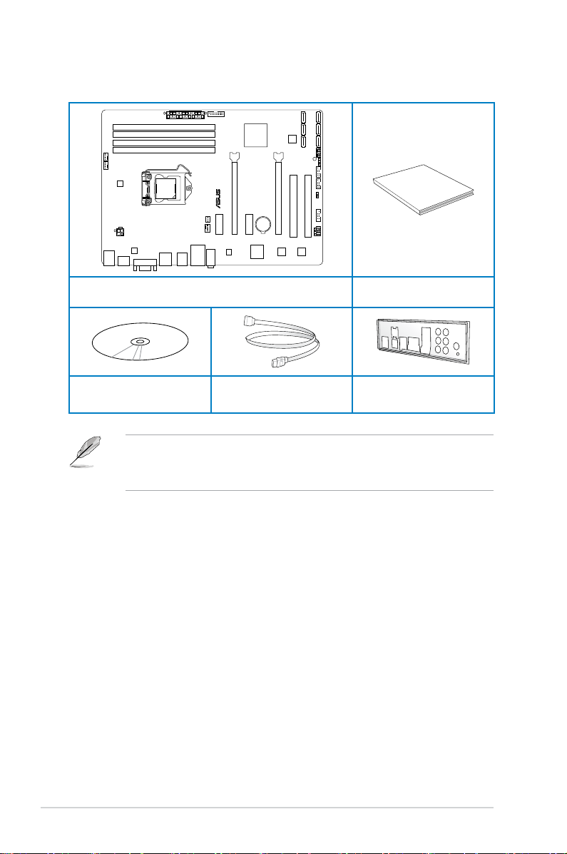
Package contents
Check your motherboard package for the following items.
ASUS P8Z77-V LX2 motherboard User Guide
Support DVD 2 x Serial ATA 6.0 Gb/s cables 1 x I/O shield
• If any of the above items is damaged or missing, contact your retailer.
• The illustrated items above are for reference only. Actual product specications may
vary with different models.
xii
Installation tools and components
1 bag of screws Philips (cross) screwdriver
PC chassis Power supply unit
Intel LGA1155 CPU Intel LGA1155 CPU Fan
DIMM SATA hard disk drive
SATA optical disc drive (optional) Graphics card (optional)
The tools and components in the table above are not included in the motherboard package.
xiii

xiv

Product introduction
1
1.1 Special features
1.1.1 Product highlights
LGA1155 socket for Intel® 2nd/3rd Generation Core™ i7 / Core™ i5 / Core™
i3, Pentium®, and Celeron® Processors
This motherboard supports Intel 2nd/3rd generation Core™ i7/i5/i3, Pentium, and Celeron
processors in the LGA1155 package. It provides great graphics and system performance with
its GPU, dual-channel DDR3 memory slots, and PCI Express 2.0/3.0 expansion slots.
Intel® Z77 Express Chipset
Intel® Z77 Express Chipset is a single-chipset that supports the 1155 socket Intel® 2nd/3rd
generation Core™ i7/i5/ i3, Pentium®, and Celeron® processors. It utilizes the serial point-topoint links, which increases bandwidth and enhances the system’s performance. It natively
supports four USB 3.0 ports for up to ten times faster transfer rate than USB 2.0, and enables
the iGPU function for Intel® integrated graphics performance.
Dual-Channel DDR3 2400(O.C.)* / 2200(O.C.)* / 2133(O.C) / 1866(O.C.) / 1600 / 1333 /
1066 Support
The motherboard supports DDR3 memory that features data transfer rates of 2400(O.C.)* /
2200(O.C.)* / 2133(O.C.) / 1866(O.C.)/ 1600 / 1333 / 1066 MHz to meet the higher bandwidth
requirements of the latest 3D graphics, multimedia, and Internet applications. The dualchannel DDR3 architecture enlarges the bandwidth of your system memory to boost system
performance.
* Due to the behavior of Intel® 2nd Generation processors, DDR3 2200 (and above)/2000/1800 MHz memory modules
will run at DDR3 2133/1866/1600 MHz frequency as default.
Complete USB 3.0 Integration
ASUS facilitates strategic USB 3.0 accessibility for both the front and rear panel — 4 USB 3.0
ports in total. Experience the latest plug & play connectivity at speeds up to 10 times faster
than USB 2.0. The P8Z77-V LX2 affords greater convenience to high speed connectivity.
Quad-GPU CrossFireX™ Support
The motherboard’s powerful Intel® Z77 platform optimizes PCIe allocation in multiple-GPU
congurations of CrossFireX. This allows you to enjoy a never before-experienced brand new
gaming style.
ASUS P8Z77-V LX2
1-1

Intel® Smart Response Technology
Intel® Smart Response Technology, an important part of Green ASUS eco-friendly computing,
reduces load and wait time, eliminates unecessary hard drive spin thus lowering power
usage, and uses an installed SSD (requires 18.6 GB available space) as a cache for
frequently accessed data or applications. It combines SSD performance and hard drive
capacity, operating up to six times faster than a hard-drive-only system, to boost the system’s
overall performance.
* Intel® 2nd/3rd generation Core™ processors on Windows® 7™ operating systems support Intel
Response Technology.
** An operating system must be installed on the HDD to launch Intel® Smart Response Technology.
*** The SSD is reserved for caching function.
®
Smart
Intel® Smart Connect Technology
Your computer can receive fresh updates for selected applications, even when the system
is in sleep mode. This means less time waiting for applications to update and sync with the
cloud, leading to a more efcient computing experience.
Intel® Rapid Start Technology
Intel® Rapid Start Technology allows your system to receive updates for your web
applications in real-time even when your system is in sleep mode, saving wait time and
power usage.
PCIe 3.0 Ready
PCI Express® 3.0 (PCIe 3.0) is the latest PCI Express bus standard with improved encoding
schemes that provide twice the performance of current PCIe 2.0. Total bandwidth for a x16
link reaches a maximum of 32GB/s, double the 16GB/s of PCIe 2.0 (in x16 mode). As such,
PCIe 3.0 provides users unprecedented data speeds, combined with the convenience and
seamless transition offered by complete backward compatibility with PCIe 1.0 and PCIe
2.0 devices. PCIe 3.0 will become a must-have feature for users who wish to improve and
optimize graphic performance, as well as have the latest technology available to them.
Gigabit LAN solution
The onboard LAN controller is a highly integrated Gb LAN controller. It is enhanced with an
ACPI management function to provide efcient power management for advanced operating
systems.
Chapter 1
1-2
PCIe 3.0 speed is supported by Intel® 3rd generation processors.
Chapter 1: Product introduction

8-channel high denition audio
The onboard 8-channel HD audio (High Denition Audio, previously codenamed Azalia)
CODEC enables high-quality 192KHz/24-bit audio output and jack-detect feature that
automatically detects and identies what types of peripherals are plugged into the audio
I/O jacks and noties users of inappropriate connection, which means there will be no more
confusion of Line-in, Line-out, and Mic jacks.
100% All High-quality Conductive Polymer Capacitors
This motherboard uses all high-quality conductive polymer capacitors for durability, improved
lifespan, and enhanced thermal capacity.
ErP ready
The motherboard is European Union´s Energy-related Products (ErP) ready, and ErP
requires products to meet certain energy efciency requirements in regards to energy
ASUS P8Z77-V LX2
1-3
Chapter 1

1.2 Motherboard overview
1.2.1 Before you proceed
Take note of the following precautions before you install motherboard components or change
any motherboard settings.
• Unplug the power cord from the wall socket before touching any component.
• Before handling components, use a grounded wrist strap or touch a safely grounded
object or a metal object, such as the power supply case, to avoid damaging them due
to static electricity.
• Hold components by the edges to avoid touching the ICs on them.
• Whenever you uninstall any component, place it on a grounded antistatic pad or in the
bag that came with the component.
• Before you install or remove any component, switch off the ATX power supply and
detach its power cord. Failure to do so may cause severe damage to the motherboard,
peripherals, or components.
Chapter 1
1-4
Chapter 1: Product introduction
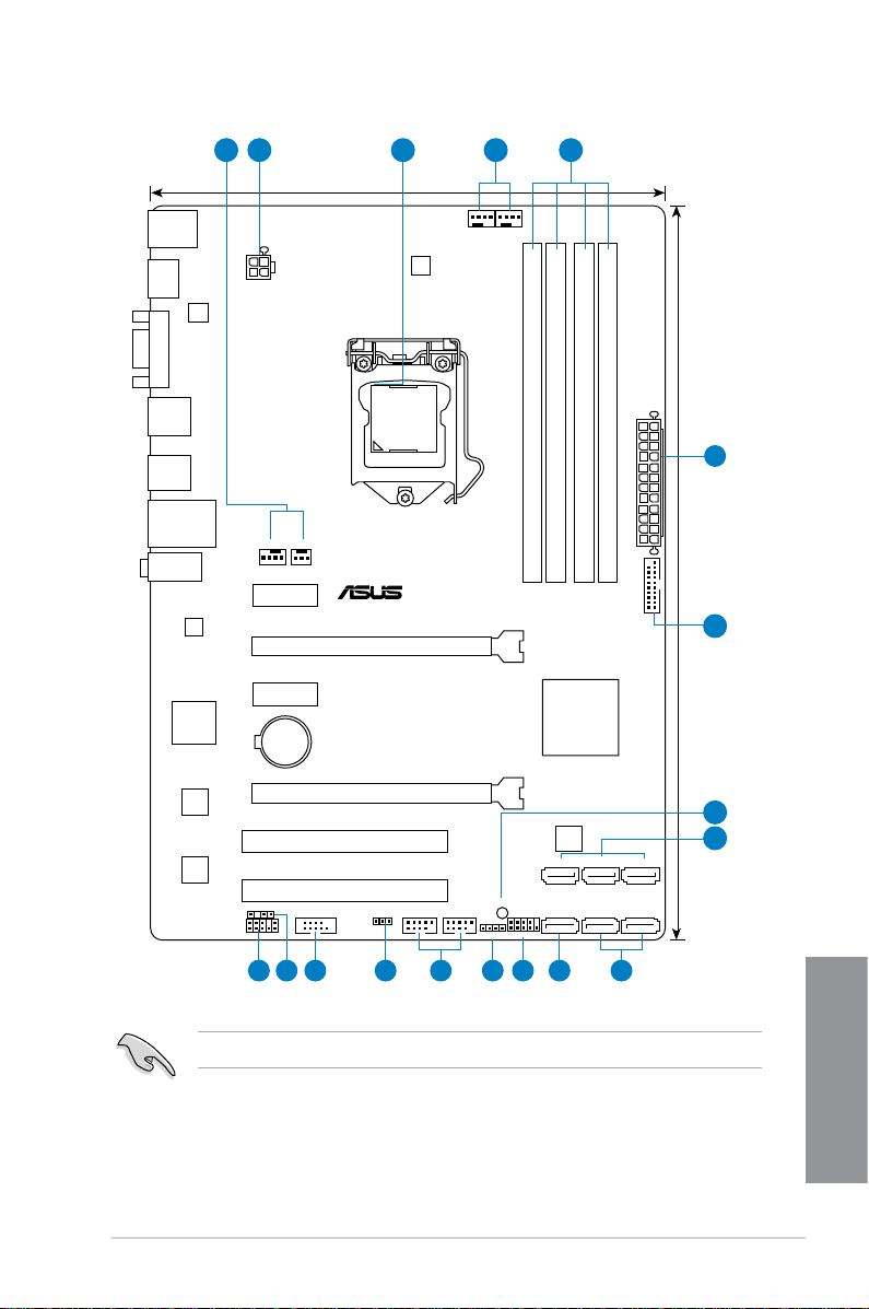
1.2.2 Motherboard layout
P8Z77-V LX2
PCIEX16_1
PCIEX16_2
PCIEX1_2
PCIEX1_1
PCI1
PCI2
USB78 USB56
USB3_34
SPDIF_OUT
AAFP
CPU_FAN
CHA_FAN2
CHA_FAN1
PWR_FAN
Lithium Cell
CMOS Power
Super
I/O
ASM
1442
DIGI
+VRM
RTL
8111F
COM1
8Mb
BIOS
SB_PWR
SPEAKER
F_PANEL
SATA3G_3 SATA3G_2 SATA3G_1
SATA3G_4 SATA6G_2 SATA6G_1
CLRTC
21.3cm(8.4in)
30.5cm(12.0in)
Intel
®
Z77
DDR3 DIMM_A1 (64bit, 240-pin module)
DDR3 DIMM_A2 (64bit, 240-pin module)
DDR3 DIMM_B1 (64bit, 240-pin module)
DDR3 DIMM_B2 (64bit, 240-pin module)
asmedia
ASM1083
ALC887
-VD2
EATXPWR
LGA1155
AUDIO
KBMS
LAN_USB12
LAN3
_USB12
USB34
HDMI
VGA
ATX12V
1 2 43 1
2
7
6
14 13 12 11 879
5
10
15
ASUS P8Z77-V LX2
Refer to 2.2.1 Rear I/O connection for more information about rear panel connectors.
1-5
Chapter 1

Layout contents
Connectors/Jumpers/Slots/LED Page
1. CPU, Chassis and power fan connectors
(4-pin CPU_FAN, 4-pin CHA_FAN1/2, 3-pin PWR_FAN)
2. EATX power connectors (24-pin EATXPWR, 4-pin EATX12V) 1-26
3. Intel® CPU socket
4. DDR3 DIMM sockets 1-7
5. USB 3.0 connector (20-1 pin USB3_34) 1-24
6. Onboard LED (SB_PWR) 1-19
7. Intel® Z77 Serial ATA 3.0 Gb/s connectors (7-pin SATA3G_1–4 [blue]) 1-25
8. Intel® Z77 Serial ATA 6.0 Gb/s connectors (7-pin SATA6G_1/2 [gray]) 1-20
9. System panel connector (10-1 pin F_PANEL) 1-27
10. Speaker connector (4-pin SPEAKER) 1-28
11. USB 2.0 connectors (10-1 pin USB56, USB78) 1-21
12. Clear RTC RAM (3-pin CLRTC) 1-18
13. Serial port connectors (10-1 pin COM1) 1-19
14. Digital audio connector (4-1 pin SPDIF_OUT) 1-22
15. Front panel audio connector (10-1 pin AAFP) 1-22
1-23
Chapter 1
1-6
Chapter 1: Product introduction
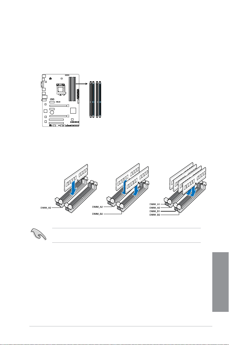
1.2.3 System memory
P8Z77-V LX2
P8Z77-V LX2 240-pin DDR3 DIMM sockets
DIMM_A1
DIMM_A2
DIMM_B1
DIMM_B2
This motherboard comes with four Double Data Rate 3 (DDR3) Dual Inline Memory Modules
(DIMM) sockets. A DDR3 module has the same physical dimensions as a DDR2 DIMM but
is notched differently to prevent installation on a DDR2 DIMM socket. DDR3 modules are
developed for better performance with less power consumption. The gure illustrates the
location of the DDR3 DIMM sockets:
Recommended memory congurations
We recommend that you install the memory modules from the blue slots for better
overclocking ability.
ASUS P8Z77-V LX2
1-7
Chapter 1

Memory congurations
You may install 1GB, 2GB, 4GB and 8GB unbuffered non-ECC DDR3 DIMMs into the DIMM
sockets.
• You may install varying memory sizes in Channel A and Channel B. The system maps
the total size of the lower-sized channel for the dual-channel conguration. Any excess
memory from the higher-sized channel is then mapped for single-channel operation.
• Due to the behavior of Intel
above)/2000/1800 MHz memory module will run at DDR3 2133/1866/1600 MHz
frequency as default.
• According to Intel
the CPU.
• Always install DIMMs with the same CAS latency. For optimum compatibility, we
recommend that you obtain memory modules from the same vendor.
• Due to the memory address limitation on 32-bit Windows OS, when you install 4GB
or more memory on the motherboard, the actual usable memory for the OS can be
about 3GB or less. For effective use of memory, we recommend that you do any of the
following:
— Use a maximum of 3GB system memory if you are using a 32-bit Windows OS.
— Install a 64-bit Windows OS when you want to install 4GB or more on the
motherboard.
For more details, refer to the Microsoft® support site at
http://support.microsoft.com/kb/929605/en-us.
• This motherboard does not support DIMMs made up of 512Mb (64MB) chips or less
(Memory chip capacity counts in Megabit, 8 Megabit/Mb = 1 Megabyte/MB).
• The default memory operation frequency is dependent on its Serial Presence Detect
(SPD), which is the standard way of accessing information from a memory module.
Under the default state, some memory modules for overclocking may operate at a
lower frequency than the vendor-marked value. To operate at the vendor-marked
or at a higher frequency, refer to section 3.4 Ai Tweaker menu for manual memory
frequency adjustment.
• For system stability, use a more efcient memory cooling system to support a full
memory load (4 DIMMs) or overclocking condition.
®
2nd Generation processor, DDR3 2200 (and
®
CPU spec, DIMM voltage below 1.65V is recommended to protect
Chapter 1
1-8
Visit the ASUS website for the latest QVL.
Chapter 1: Product introduction
P8Z77-V LX2 Motherboard Qualied Vendors Lists (QVL) DDR3 2400MHz
capability
Chip
Vendors Part No. Size SS/DS
Transcend TX2400KLU-4GK (381850)(XMP) 4GB(2x 2GB) SS — — 9 1.65V • •
Brand
Chip
Timing Voltage
NO.
* The 2400MHz memory modules above are supported on Intel® 3rd generation processors by this
motherboard; however, the actual frequency support varied depending on the O.C. margin of the
installed CPU.
** Due to Intel 2nd generation processors’ behavior, DDR3 2200 and above/2000/1800 MHz memory
module runs at DDR3 2133/1866/1600 MHz frequency as default.
DIMM socket support
(Optional)
1 DIMM 2 DIMMs 4 DIMMs
P8Z77-V LX2 Motherboard Qualified Vendors Lists (QVL) DDR3 2250MHz
capability
Vendors Part No. Size
Kingston KHX2250C9D3T1K2/4GX(XMP) 4GB(2x 2GB) DS — — — 1.65V • • •
SS/DSChip
Brand
Chip
Timing Voltage
NO.
* The 2250MHz memory modules above are supported on Intel® 3rd generation processors by this
motherboard; however, the actual frequency support varied depending on the O.C. margin of the
installed CPU.
** Due to Intel 2nd generation processors’ behavior, DDR3 2200 and above/2000/1800 MHz memory
module runs at DDR3 2133/1866/1600 MHz frequency as default.
DIMM socket support (Optional)
1 DIMM 2 DIMMs 4 DIMMs
P8Z77-V LX2 Motherboard Qualified Vendors Lists (QVL) DDR3 2200MHz
capability
Vendors Part No. Size
G.SKILL F3-17600CL8D-4GBPS(XMP) 4GB(2x 2GB) DS — — 8-8-8-24 1.65V •
KINGMAX FLKE85F-B8KJAFEIH(XMP) 4GB(2x 2GB) DS — — — 1.5V-1.7V •
SS/DSChip
* The 2200MHz memory modules above are supported on Intel
Brand
Chip
Timing Voltage
NO.
®
3rd generation processors by this
motherboard; however, the actual frequency support varied depending on the O.C. margin of the
installed CPU.
** Due to Intel 2nd generation processors’ behavior, DDR3 2200 and above/2000/1800 MHz memory
module runs at DDR3 2133/1866/1600 MHz frequency as default.
DIMM socket support (Optional)
1 DIMM 2 DIMMs 4 DIMMs
P8Z77-V LX2 Motherboard Qualified Vendors Lists (QVL) DDR3 2133MHz
capability
SS/DSChip
Vendors Part No. Size
A-DATA AX3U2133GC2G9B-DG2(XMP) 2GB SS — — 9-11-9-27 1.55~1.75V •
CORSAIR CMT4GX3M2A2133C9(XMP) 4GB(2x 2GB) DS — — 9-10-9-24 1.65V •
CORSAIR CMT4GX3M2B2133C9(XMP) 4GB(2x 2GB) DS — — 9-10-9-27 1.50V • •
GEIL GE34GB2133C9DC(XMP) 2GB DS — — 9-9-9-28 1.65V • •
GEIL GU34GB2133C9DC(XMP) 4GB(2 x 2GB) DS — — 9-9-9-28 1.65V • • •
KINGSTON KHX2133C9AD3T1K2/4GX(XMP) 4GB(2x 2GB ) DS — — — 1.65V • • •
KINGSTON KHX2133C9AD3X2K2/4GX(XMP) 4GB(2 x 2GB) DS — — 9-11-9-27 1.65V • • •
KINGSTON KHX2133C9AD3T1K4/8GX(XMP) 8GB(4 x 2GB) DS — — 9-11-9-27 1.65V • • •
KINGSTON KHX2133C9AD3T1FK4/8GX(XMP) 8GB(4x 2GB) DS — — — 1.65V • • •
Brand
Chip
Timing Voltage
NO.
ASUS P8Z77-V LX2
DIMM socket support (Optional)
1 DIMM 2 DIMMs 4 DIMMs
1-9
Chapter 1
P8Z77-V LX2 Motherboard Qualified Vendors Lists (QVL) DDR3 2000MHz
capability
SS/DSChip
Vendors Part No. Size
Apacer 78.AAGD5.9KD(XMP) 6GB(3 x 2GB) DS — — 9-9-9-27 1.65V • • •
CORSAIR CMZ4GX3M2A2000C10(XMP) 4GB(2 x 2GB) SS — — 10-10-10-27 1.50V • • •
CORSAIR CMT6GX3M3A2000C8(XMP) 6GB(3 x 2GB) DS — — 8-9-8-24 1.65V • •
G.SKILL F3-16000CL9D-4GBFLS(XMP) 4GB(2 x 2GB) DS — — 9-9-9-24 1.65V • • •
G.SKILL F3-16000CL9D-4GBTD(XMP) 4GB(2 x 2GB) DS — — 9-9-9-27 1.65V • • •
G.SKILL F3-16000CL6T-6GBPIS(XMP) 6GB(3x 2GB ) DS — — 6-9-6-24 1.65V • •
GEIL GUP34GB2000C9DC(XMP) 4GB(2 x 2GB) DS — — 9-9-9-28 1.65V
KHX2000C9AD3T1K2/
KINGSTON
4GX(XMP)
KHX2000C9AD3W1K2/
KINGSTON
4GX(XMP)
KHX2000C9AD3T1K2/
KINGSTON
4GX(XMP)
KHX2000C9AD3W1K3/
KINGSTON
6GX(XMP)
KHX2000C9AD3T1K3/
KINGSTON
6GX(XMP)
Transcend TX2000KLN-8GK(XMP) 8GB(2 x 4GB) DS — — — 1.6V • • •
4GB(2x 2GB ) DS — — — 1.65V • • •
4GB(2x 2GB ) DS — — — 1.65V • •
4GB(2 x 2GB) DS — — 9 1.65V • • •
6GB(3x 2GB ) DS — — — 1.65V • •
6GB(3x 2GB ) DS — — — 1.65V • •
Brand
Chip
Timing Voltage
NO.
DIMM socket support (Optional)
1 DIMM 2 DIMMs 4 DIMMs
P8Z77-V LX2 Motherboard Qualified Vendors Lists (QVL) DDR3 1866MHz
capability
SS/DSChip
Vendors Part No. Size
CORSAIR CMT4GX3M2A1866C9(XMP) 4GB(2 x 2GB) DS — — 9-9-9-24 1.65V • • •
CORSAIR CMT6GX3MA1866C9(XMP) 6GB(3 x 2GB) DS — — 9-9-9-24 1.65V • •
CORSAIR CMZ8GX3M2A1866C9(XMP) 8GB(2 x 4GB) DS — — 9-10-9-27 1.50V • • •
F3-14900CL9D-
G.SKILL
G.SKILL
KINGSTON
KINGSTON
8GBXL(XMP)
F3-14900CL9Q8GBXL(XMP)
KHX1866C9D3T1K3/
3GX(XMP)
KHX1866C9D3T1K3/
6GX(XMP)
8GB(2 x 4GB) DS — — 9-10-9-28 1.5V • • •
8GB(2GB x 4) DS — — 9-9-9-24 1.6V • • •
3GB(3 x 1GB) SS — — — 1.65V • • •
6GB(3 x 2GB) DS — — — 1.65V • • •
Brand
Chip
Timing Voltage
NO.
DIMM socket support (Optional)
1 DIMM 2 DIMMs 4 DIMMs
Chapter 1
1-10
Chapter 1: Product introduction
P8Z77-V LX2 Motherboard Qualified Vendors Lists (QVL) DDR3 1600MHz
capability
Vendors Part No. Size
A-DATA AM2U16BC2P1 2GB SS A-DATA
A-DATA AD31600E001GM(O)U3K 3GB(3 x 1GB) SS — — 8-8-8-24
A-DATA AM2U16BC4P2 4GB DS A-DATA
A-DATA AX3U1600GC4G9-2G(XMP) 8GB(2 x 4GB) DS — — 9-9-9-24
A-DATA AX3U1600XC4G79-2X(XMP) 8GB(2 x 4GB) DS — — 7-9-7-21
CORSAIR TR3X3G1600C8D(XMP) 3GB(3 x 1GB) SS — — 8-8-8-24 1.65V • •
CORSAIR CMD12GX3M6A1600C8(XMP) 12GB(6x2GB) DS — — 8-8-8-24 1.65V • • •
CORSAIR CMP4GX3M2A1600C8(XMP) 4GB(2 x 2GB) DS — — 8-8-8-24 1.65V • • •
CORSAIR CMP4GX3M2A1600C9(XMP) 4GB(2 x 2GB) DS — — 9-9-9-24 1.65V • • •
CORSAIR CMP4GX3M2C1600C7(XMP) 4GB(2 x 2GB) DS — — 7-8-7-20 1.65V • • •
CORSAIR CMX4GX3M2A1600C9(XMP) 4GB(2 x 2GB) DS — — 9-9-9-24 1.65V • •
CORSAIR CMX4GX3M2A1600C9(XMP) 4GB(2 x 2GB) DS — — 9-9-9-24 1.65V • • •
CORSAIR TR3X6G1600C8 G(XMP) 6GB(3 x 2GB) DS — — 8-8-8-24 1.65V • • •
CORSAIR TR3X6G1600C8D G(XMP) 6GB(3 x 2GB) DS — — 8-8-8-24 1.65V • • •
CORSAIR TR3X6G1600C9 G(XMP) 6GB(3 x 2GB) DS — — 9-9-9-24 1.65V • • •
CORSAIR CMP8GX3M2A1600C9(XMP) 8GB(2 x 4GB) DS — — 9-9-9-24 1.65V • • •
CORSAIR CMZ8GX3M2A1600C7R(XMP) 8GB(2 x 4GB) DS — — 7-8-7-20 1.50V • • •
CORSAIR CMX8GX3M4A1600C9(XMP) 8GB(4 x 2GB) DS — — 9-9-9-24 1.65V • • •
Crucial BL25664BN1608.16FF(XMP) 6GB(3 x 2GB) DS — — — — • • •
G.SKILL F3-12800CL9D-2GBNQ(XMP) 2GB(2 x 1GB) SS — — 9-9-9-24 1.5V • • •
G.SKILL F3-12800CL7D-4GBRH(XMP) 4GB(2 x 2GB) SS — — 7-7-7-24 1.6V • • •
G.SKILL F3-12800CL7D-4GBRM(XMP) 4GB(2 x 2GB) DS — — 7-8-7-24 1.6V • • •
G.SKILL F3-12800CL8D-4GBRM(XMP) 4GB(2 x 2GB) DS — — 8-8-8-24 1.60V • • •
G.SKILL F3-12800CL9D-4GBECO(XMP) 4GB(2 x 2GB) DS — — 9-9-9-24 XMP 1.35V • • •
G.SKILL F3-12800CL9D-4GBRL(XMP) 4GB(2 x 2GB) DS — — 9-9-9-24 1.5V • • •
G.SKILL F3-12800CL9T-6GBNQ(XMP) 6GB(3 x 2GB) DS — — 9-9-9-24 1.5V~1.6V • • •
G.SKILL F3-12800CL7D-8GBRH(XMP) 8GB(2 x 4GB) DS — — 7-8-7-24 1.6V • • •
G.SKILL F3-12800CL8D-8GBECO(XMP) 8GB(2 x 4GB) DS — — 8-8-8-24 XMP 1.35V • • •
G.SKILL F3-12800CL9D-8GBRL(XMP) 8GB(2 x 4GB) DS — — 9-9-9-24 1.5V • • •
GEIL GET316GB1600C9QC(XMP)
GEIL GV34GB1600C8DC(XMP) 2GB DS — — 8-8-8-28 1.6V • • •
KINGMAX FLGD45F-B8MF7 MAEH(XMP) 1GB SS — — 7 — • •
KINGMAX FLGE85F-B8KJ9A FEIS(XMP) 2GB DS — — — — • • •
KINGMAX FLGE85F-B8MF7 MEEH(XMP) 2GB DS — — 7 — •
KINGSTON KHX1600C9D3P1K2/4G 4GB(2 x 2GB) SS — — — 1.5V • • •
KINGSTON KHX1600C9D3K3/12GX(XMP) 12GB(3x4GB) DS — — 9-9-9-27 1.65V • • •
16GB(4x
4GB)
SS/DSChip
DS — — 9-9-9-28 1.6V • • •
Chip NO. Timing Voltage
Brand
3CCD-150
9A EL1126T
3CCD-150
9A EL1126T
— — • • •
— — • • •
DIMM socket support
(Optional)
1 DIMM 2 DIMMs 4 DIMMs
1.65V-
• •
1.85V
1.55V-
• • •
1.75V
1.55V-
• • •
1.75V
ASUS P8Z77-V LX2
1-11
Chapter 1
P8Z77-V LX2 Motherboard Qualified Vendors Lists (QVL) DDR3 1600MHz
capability
Vendors Part No. Size
KINGSTON
KINGSTON KHX1600C9AD3/2G 2GB DS — — — 1.65V • • •
KINGSTON KVR1600D3N11/2G-ES 2GB DS KTC
KINGSTON KHX1600C7D3K2/4GX(XMP) 4GB(2x 2GB ) DS — — — 1.65V • • •
KINGSTON KHX1600C8D3K2/4GX(XMP) 4GB(2 x 2GB) DS — — 8 1.65V • • •
KINGSTON KHX1600C8D3T1K2/4GX(XMP) 4GB(2 x 2GB) DS — — 8 1.65V • • •
KINGSTON KHX1600C9D3K2/4GX(XMP) 4GB(2 x 2GB) DS — — 9 1.65V • • •
KINGSTON KHX1600C9D3LK2/4GX(XMP) 4GB(2 x 2GB) DS — — 9 XMP 1.35V • • •
KINGSTON KHX1600C9D3X2K2/4GX(XMP) 4GB(2 x 2GB) DS — — 9-9-9-27 1.65V • • •
KINGSTON KHX1600C9D3T1K3/6GX(XMP) 6GB(3x 2GB ) DS — — — 1.65V • • •
KINGSTON KHX1600C9D3K3/6GX(XMP) 6GB(3 x 2GB) DS — — 9 1.65V • • •
KINGSTON
KINGSTON KHX1600C9D3K2/8GX(XMP) 8GB(2 x 4GB) DS — — 9-9-9-27 1.65V • • •
KINGSTON KHX1600C9D3P1K2/8G 8GB(2 x 4GB) DS — — — 1.5V • • •
Super Talent WA160UX6G9 6GB(3 x 2GB) DS — — 9 — • •
Transcend JM1600KLN-8GK 8GB(4GBx2) DS Transcend
Asint SLZ3128M8-EGJ1D(XMP) 2GB DS Asint
Elixir M2P2G64CB8HC9N-DG(XMP) 2GB DS — — — — • • •
Mushkin 998659(XMP) 6GB(3 x 2GB) DS — — 9-9-9-24 1.5~1.6V • • •
P8Z77-V LX2 Motherboard Qualified Vendors Lists (QVL) DDR3 1333MHz
capability
Vendors Part No. Size
A-DATA AD31333001GOU 1GB SS A-Data
A-DATA AD3U1333C2G9 2GB SS A-DATA 3CCD-1509HNA1126L — — • • •
A-DATA AD63I1B0823EV 2GB SS A-Data 3CCA-1509A — — • • •
A-DATA AM2U139C2P1 2GB SS ADATA 3CCD-1509A EL1127T — — • • •
A-DATA AX3U1333C2G9-BP 2GB SS — — — — • • •
A-DATA AD31333G001GOU
A-DATA
A-DATA AD31333G002GMU 2GB DS — — 8-8-8-24
A-DATA AD63I1C1624EV 4GB DS A-Data 3CCA-1509A — — • • •
A-DATA AM2U139C4P2 4GB DS ADATA 3CCD-1509A EL1127T — — • • •
A-DATA SU3U1333W8G9-B 8GB DS ELPIDA J4208BASE-DJ-F — — •
Apacer 78.A1GC6.9L1 2GB DS Apacer AM5D5808DEWSBG — — • • •
Apacer 78.A1GC6.9L1 2GB DS Apacer AM5D5808FEQSBG 9 — • • •
Apacer AU02GFA33C9NBGC 2GB DS Apacer AM5D5808APQSBG — — • • •
Apacer 78.B1GDE.9L10C 4GB DS Apacer AM5D5908CEHSBG — — • • •
CORSAIR CM3X1024-1333C9 1GB SS — — 9-9-9-24 1.60V • • •
Chapter 1
CORSAIR TR3X3G1333C9 G
CORSAIR TR3X6G1333C9 G
CORSAIR
CORSAIR TW3X4G1333C9D G
CORSAIR CM3X4GA1333C9N2 4GB DS CORSAIR
CORSAIR CMX4GX3M1A1333C9 4GB DS — — 9-9-9-24 1.50V • • •
CORSAIR CMD8GX3M4A1333C7
KHX1600C9D3T1BK3/
12GX(XMP)
KHX1600C9D3T1BK3/6GX
(XMP)
AXDU1333GC2
G9-2G(XMP)
CMD24GX3M6A
1333C9(XMP)
SS/DSChip
12GB(3x4GB) DS — — 9-9-9-27 1.65V • • •
6GB(3 x 2GB) DS — — 9-9-9-27 1.65V • • •
SS/
Chip Brand Chip NO. Timing Voltage
DS
3GB
SS — — 8-8-8-24
(3 x 1GB)
4GB
SS — — 9-9-9-24
(2 x 2GB)
3GB
SS — — 9-9-9-24 1.50V • • •
(3 x 1GB)
6GB
SS — — 9-9-9-24 1.50V • •
(3x 2GB)
24GB
DS — — 9-9-9-24 1.60V • • •
(6 x 4GB)
4GB
DS — — 9-9-9-24 1.50V • • •
(2 x 2GB)
8GB
DS — — 7-7-7-20 1.60V • • •
(4 x 2GB)
Chip NO. Timing Voltage
Brand
D1288JPN
DPLD9U
TK483
PCW3
3128M8
-GJ1D
AD30908C8D-151C
E0906
256MBDCJ
GELC0401136
11-11-
1.35V-1.5V • • •
11-28
— — • • •
9-9-9-24 1.6V • • •
— — • • •
1.65-
1.85V
1.25V-
1.35V(low
voltage)
1.65-
1.85V
9-9-9-24 — • • •
DIMM socket support
(Optional)
1 DIMM 2 DIMMs 4 DIMMs
DIMM socket support
(Optional)
1 DIMM 2 DIMMs 4 DIMMs
• • •
• • •
• •
1-12
(continued on the next page)
Chapter 1: Product introduction
Vendors Part No. Size
Crucial CT12864BA1339.8FF 1GB SS Micron 9FF22D9KPT 9 — • • •
Crucial CT25664BA1339.16FF 2GB DS Micron 9KF27D9KPT 9 — • • •
Crucial
ELPIDA EBJ10UE8EDF0-DJ-F 1GB SS ELPIDA J1108EDSE-DJ-F —
ELPIDA EBJ21UE8EDF0-DJ-F 2GB DS ELPIDA J1108EDSE-DJ-F —
G.SKILL
G.SKILL
G.SKILL
G.SKILL
G.SKILL
G.SKILL
GEIL GET316GB1333C9QC
GEIL GV32GB1333C9DC
GEIL GG34GB1333C9DC
GEIL GV34GB1333C9DC
GEIL GVP34GB1333C7DC
Hynix HMT112U6TFR8A-H9 1GB SS Hynix H5TC1G83TFRH9A —
Hynix HMT325U6BFR8C-H9 2GB SS Hynix H5TQ2G83BFRH9C — — • • •
Hynix HMT125U6TFR8A-H9 2GB DS Hynix H5TC1G83TFRH9A —
Hynix HMT351U6BFR8C-H9 4GB DS Hynix H5TQ2G83BFRH9C — — • • •
KINGMAX FLFD45F-B8KL9 NAES 1GB SS KINGMAX KKB8FNWBFGNX-27A — — • • •
KINGMAX FLFE85F-C8KF9 CAES 2GB SS KINGMAX KFC8FMFXF-DXX-15A — — • • •
KINGMAX FLFE85F-C8KL9 NAES 2GB SS KINGMAX KFC8FNLXF-DXX-15A — — • • •
KINGMAX FLFE85F-C8KM9 NAES 2GB SS KINGMAX KFC8FNMXF-BXX-15A — — • • •
KINGMAX FLFE85F-B8KL9 NEES 2GB DS KINGMAX KKB8FNWBFGNX-26A — — • • •
KINGMAX FLFF65F-C8KL9 NEES 4GB DS KINGMAX KFC8FNLXF-DXX-15A — — • • •
KINGMAX FLFF65F-C8KM9 NEES 4GB DS KINGMAX KFC8FNMXF-BXX-15A — — • • •
KINGSTON
KINGSTON
KINGSTON KVR1333D3S8N9/2G 2GB SS Micron IID77 D9LGK — 1.5V • • •
KINGSTON
KINGSTON
KINGSTON KVR1333D3N9/2G 2GB DS KTC D1288JPNDPLD9U 9 1.5V • • •
KINGSTON KVR1333D3N9/2G 2GB DS ELPIDA J1108BDSE-DJ-F 9 1.5V • • •
KINGSTON
KINGSTON
KINGSTON
KINGSTON
KINGSTON
KINGSTON
KINGSTON KVR1333D3N9/4G 4GB DS KTC D2568JENCNGD9U — 1.5V • • •
KINGSTON KVR1333D3N9/4G 4GB DS Hynix H5TQ2G83AFR — — • • •
KINGSTON
Micron
Micron
BL25664BN13
37.16FF (XMP)
F3-10600CL8
D-2GBHK(XMP)
F3-10600CL
9D-2GBNQ
F3-10666CL7
T-3GBPK(XMP)
F3-10666CL8D4GBECO(XMP)
F3-10666CL
7T-6GBPK(XMP)
F3-10666C
L7D-8GBRH(XMP)
KVR1333D3
N9/1G(low prole)
KVR1333D3
N9/2G(low prole)
KVR1333D3S
8N9/2G-SP(low prole)
KVR1333D3
N9/2G(low prole)
KVR1333D3
N9/2G-SP(low prole)
KVR1333D3N9/2G-
SP(low prole)
KHX1333C7
D3K2/4GX(XMP)
KHX1333C9D3UK2/
4GX(XMP)
KVR1333D
3N9/4G(low prole)
KVR1333D
3N9/4G(low prole)
KVR1333D3N9/4G-
SP(low prole)
MT4JTF12864AZ1G4D1
MT8JTF12864AZ1G4F1
SS/
Chip Brand Chip NO. Timing Voltage
DS
6GB
DS — — 7-7-7-24 1.65V • • •
(3 x 2GB)
1GB SS G.SKILL — — — • • •
2GB
SS — — 9-9-9-24 1.5V • • •
(2 x 1GB)
3GB
SS — — 7-7-7-18 1.5~1.6V • • •
(3 x 1GB)
4GB
DS — —
(2 x 2GB)
6GB
DS — — 7-7-7-18 1.5~1.6V • •
(3 x 2GB)
8GB
DS — — 7-7-7-21 1.5V • • •
(2 x 4GB)
16GB
DS — — 9-9-9-24 1.5V •
(4 x 4GB)
2GB
DS — — 9-9-9-24 1.5V • • •
(2 x 1GB)
4GB
DS GEIL GL1L128M88BA12N 9-9-9-24
(2 x 2GB)
4GB
DS — — 9-9-9-24 1.5V • • •
(2 x 2GB)
4GB
DS — — 7-7-7-24 1.5V • • •
(2 x 2GB)
1GB SS ELPIDA J1108BDBG-DJ-F 9 1.5V • • •
2GB SS Hynix H5TQ2G83AFRH9C 9 — • • •
2GB SS ELPIDA J2108BCSE-DJ-F — 1.5V • • •
2GB DS ELPIDA J1108BFBG-DJ-F 9 1.5V • • •
2GB DS KTC D1288JEMFNGD9U — 1.5V • • •
2GB DS KINGSTON D1288JPSFPGD9U — 1.5V • • •
4GB
DS — — 7 1.65V • • •
(2 x 2GB)
4GB
DS — — 9
(2 x 2GB)
4GB DS ELPIDA J2108BCSE-DJ-F 9 1.5V • • •
4GB DS ELPIDA J2108BCSE-DJ-F — 1.5V • • •
4GB DS KINGSTON D2568JENCPGD9U — 1.5V • • •
1GB SS Micron OJD12D9LGQ — — • • •
1GB SS Micron 9FF22D9KPT 9 — • • •
8-8-88-24
DIMM socket support
(Optional)
1 DIMM 2 DIMMs 4 DIMMs
1.35V(low
• • •
voltage)
1.35V(low
• •
voltage)
XMP
• • •
1.35V
1.3V(low
• • •
voltage)
1.35V(low
• • •
voltage)
1.35V(low
• • •
voltage)
XMP
•
1.25V
(continued on the next page)
Chapter 1
ASUS P8Z77-V LX2
1-13
Vendors Part No. Size
Micron
Micron
Micron
Micron
NANYA
PSC AL7F8G73F-DJ2 1GB SS PSC A3P1GF3FGF — — • • •
PSC AL8F8G73F-DJ2 2GB DS PSC A3P1GF3FGF — — • • •
SAMSUNG M378B2873FHS-CH9 1GB SS SAMSUNG K4B1G0846F — — • • •
SAMSUNG M378B5773DH0-CH9 2GB SS SAMSUNG K4B2G0846D — — • • •
SAMSUNG M378B5673FH0-CH9 2GB DS SAMSUNG K4B1G0846F — — • • •
SAMSUNG M378B5273CH0-CH9 4GB DS SAMSUNG K4B2G0846C — — • • •
SAMSUNG M378B1G73AH0-CH9 8GB DS SAMSUNG K4B4G0846A-HCH9 — — • •
Super Talent W1333UA1GH 1GB SS Hynix H5TQ1G83TFR 9 — • • •
Super Talent W1333UX2G8(XMP)
Super Talent W1333UB2GS 2GB DS SAMSUNG K4B1G0846F 9 — • • •
Super Talent W1333UB4GS 4GB DS SAMSUNG K4B2G0846C — — • • •
Super Talent W1333UX6GM
Transcend JM1333KLN-2G 2GB SS Micron 0YD77D9LGK — — • • •
Transcend JM1333KLN-2G 2GB SS Hynix H5TQ2G83BZRH9C — — • • •
Transcend JM1333KLU-2G 2GB DS Transcend TK243PDF3 — — • • •
Transcend TS256MLK64V3U 2GB DS Micron 9GF27D9KPT — — • •
Century
Elixir M2F2G64CB88D7N-CG 2GB SS Elixir N2CB2G80DN-CG — — • •
Elixir M2F2G64CB88G7N-CG 2GB SS Elixir N2CB2G80GN-CG — — • •
Elixir
Elixir
KINGSHARE KSRPCD313332G 2GB DS PATRIOT PM128M8D385-15 — — • • •
KINGSTEK KSTD3PC-10600 2GB SS MICRON PE911-125E — — • •
Kingtiger 2GB DIMM PC3-10666 2GB DS SAMSUNG
MARKVI
SION
MARKVI
SION
PATRIOT PSD31G13332H 1GB DS — — 9 — •
PATRIOT PSD31G13332 1GB DS PATRIOT PM64M8D38U-15 — — • •
PATRIOT PSD32G13332H 2GB DS — — — — • • •
RAMAXEL
RAMAXEL
RiDATA C304627CB1AG22Fe 2GB DS RiDATA N/A 9 — • • •
RiDATA E304459CB1AG32Cf 4GB DS RiDATA N/A 9 — • • •
SILICON
POWER
SILICON
POWER
SILICON
Chapter 1
POWER
TAKEMS
TAKEMS
TAKEMS
TAKEMS
TAKEMS
UMAX E41302GP0-73BDB 2GB DS UMAX U2S24D30TP-13 — — • • •
WINTEC 3WVS31333-2G-CNR 2GB DS AMPO AM3420803-13H — — • • •
SS/
Chip Brand Chip NO. Timing Voltage
DS
MT8JTF25664AZ1G4D1
MT8JTF25664AZ1G4M1
MT16JTF25664AZ1G4F1
MT16JTF51264AZ1G4D1
NT4GC64B8HG0NFCG
PC3-10600 DDR3
-1333 9-9-9
M2F4G64CB8HB5NCG
M2F4G64CB8HD5NCG
BMD32048M
1333C9-1123
BMD34096M
1333C9-1124
RMR1870ED48
E8F-1333
RMR1870EC58
E9F-1333
SP001GBLTU133S01 1GB SS NANYA NT5CB128M8AN-CG 9 — • • •
SP001GBLTU133S02 1GB SS Elixir N2CB1680AN-C6 9 — • • •
SP002GBLTU133S02 2GB DS Elixir N2CB1680AN-C6 9 — • • •
TMS1GB364D081107EY
TMS1GB364D081138EY
TMS2GB364D081107EY
TMS2GB364D081138EY
TMS2GB364D082138EW
2GB SS Micron OJD12D9LGK — — • • •
2GB SS MICRON IJM22 D9PFJ — — • • •
2GB DS Micron 9KF27D9KPT 9 — • • •
4GB DS Micron OLD22D9LGK — — • • •
4GB DS NANYA NT5CB256M8GN-CG — — • • •
2GB
SS — — 8 — • •
(2x 1GB)
6GB
DS Micron 0BF27D9KPT 9-9-9-24 1.5V • • •
(3x 2GB)
1GB SS NANYA NT5CB128M8DN-CF — — • • •
4GB DS Elixir N2CB2G80BN-CG — — • • •
4GB DS Elixir N2CB2G80DN-CG — — • •
SEC 904 HCH9
K4B1G0846D
2GB DS
4GB DS
2GB DS ELPIDA J1108BDBG-DJ-F — — • • •
4GB DS ELPIDA J2108BCSE-DJ-F — — • • •
1GB SS — — 7-7-7-20 1.5V • •
1GB SS — — 8-8-8-24 1.5V • •
2GB DS — — 7-7-7-20 1.5V • •
2GB DS — — 8-8-8-24 1.5V • •
2GB DS — — 8-8-8-24 1.5V • •
MARKVI
M3D1288P-13 — — • • •
SION
MARKVI
M3D2568E-13 — — • • •
SION
— — • • •
DIMM socket support
(Optional)
1 DIMM 2 DIMMs 4 DIMMs
1-14
Chapter 1: Product introduction
P8Z77-V LX2 Motherboard Qualied Vendors Lists (QVL) DDR3 1066MHz
capability
Vendors Part No. Size
Crucial CT12864BA1067.8FF 1GB SS Micron 9GF22D9KPT 7 — • • •
Crucial CT25664BA1067.16FF 2GB DS Micron 9HF22D9KPT 7 — • • •
ELPIDA EBJ10UE8EDF0-AE-F 1GB SS ELPIDA J1108EDSE-DJ-F — 1.35V(low voltage) • • •
ELPIDA EBJ21UE8EDF0-AE-F 2GB DS ELPIDA J1108EDSE-DJ-F — 1.35V(low voltage) • • •
KVR1066D3N7/1G (low
KINGSTON
prole)
KINGSTON KVR1066D3N7/2G 2GB DS ELPIDA J1108BDSE-DJ-F 7 1.5V • • •
KINGSTON KVR1066D3N7/4G 4GB DS Hynix H5TQ2G83AFR 7 1.5V • • •
MT8JTF12864AZ-
Micron
1G1F1
MT16JTF25664AZ-
Micron
1G1F1
Kingtiger 2GB DIMM PC3-8500 2GB DS Hynix
SS/DSChip
1GB SS ELPIDA J1108BFSE-DJ-F 7 1.5V • • •
1GB SS Micron 9GF22D9KPT 7 — • • •
2GB DS Micron 9HF22D9KPT 7 — • • •
Chip NO. Timing Voltage
Brand
H5TQ1G83AFP
G7C
— — • • •
Side(s): SS — Single-sided DS — Double-sided DIMM support:
• 1 DIMM: Supports one (1) module inserted into any slot as Single-channel memory
conguration. We suggest that you install the module into A2 slot.
• 2 DIMMs: Supports two (2) modules inserted into either the blue slots or the black
slots as one pair of Dual-channel memory conguration. We suggest that
you install the modules into slots A2 and B2 for better compatibility.
• 4 DIMMs: Supports four (4) modules inserted into both the blue and black slots as two
pairs of Dual-channel memory conguration.
• ASUS exclusively provides hyper DIMM support function.
• Hyper DIMM support is subject to the physical characteristics of individual CPUs. Load
the X.M.P. or D.O.C.P. settings in the BIOS for the hyper DIMM support.
• Visit the ASUS website for the latest QVL.
DIMM socket support (Optional)
1 DIMM 2 DIMMs 4 DIMMs
ASUS P8Z77-V LX2
1-15
Chapter 1
1.2.4 Expansion slots
Unplug the power cord before adding or removing expansion cards. Failure to do so may
cause you physical injury and damage motherboard components.
Slot No. Slot Description
1 PCIe 2.0 x1_1 slot
2 PCIe 3.0/2.0 x16_1 slot [blue] (at 16x mode)
3 PCIe 2.0 x1_2 slot
4 PCIe 2.0 x16_2 slot [black] (at 4x mode)
5 PCI slot_1
6 PCI slot_2
Chapter 1
1-16
VGA conguration
Single VGA/PCIe card
PCI Express operating mode
PCIe 2.0 x16_1 PCIe 2.0 x16_2
x16
(Recommend for single VGA)
N/A
Dual VGA/PCIe card x16 x4
Chapter 1: Product introduction
Loading…
Скачать файл PDF «ASUS P8Z77V_LX2 Руководство по эксплуатации» (6.08 Mb)
Популярность:
3591 просмотры
Подсчет страниц:
156 страницы
Тип файла:
Размер файла:
6.08 Mb
Google Ads: