
Руководства пользователя
Версия E10276
91.95 KB
2015/03/31
HDMI insert (English)
Версия C9142
3.63 MB
2014/05/20
P8B75-M User’s Manual (Simplified Chinese)
Версия E9142
3.04 MB
2014/04/23
P8B75-M User’s Manual (English)
Версия E7993
3.03 MB
2013/01/23
P8B75-M User’s Manual (English)
Версия E7437
3.03 MB
2012/09/28
P8B75-M User’s Manual (English)
Версия E7142
4.66 MB
2012/05/08
P8B75-M User’s Manual (English)
Версия T7142
3.67 MB
2012/04/25
P8B75-M User’s Manual(Traditional Chinese)
Версия C7142
3.43 MB
2012/04/13
P8B75-M User’s Manual (Simplified Chinese)
Версия F7142
3.46 MB
2012/04/10
P8B75-M user’s manual(French)
Версия U7142
1.01 MB
2012/04/09
P8B75-M European Quick Start Guide for Multiple Languages
Версия A7142
1.53 MB
2012/04/09
P8B75-M Asian Quick Start Guide for Multiple Languages
Версия J7142
3.73 MB
2012/03/28
P8B75-M User’s Manual (Japanese)
-
Драйверы
79
-
Инструкции по эксплуатации
10
Языки:
ASUS P8B75-M инструкция по эксплуатации
(76 страниц)
- Языки:Английский
-
Тип:
PDF -
Размер:
4.66 MB -
Описание:
P8B75-M User’s Manual (English)
Просмотр
ASUS P8B75-M инструкция по эксплуатации
(78 страниц)
- Языки:Английский
-
Тип:
PDF -
Размер:
3.03 MB -
Описание:
P8B75-M User’s Manual (English)
Просмотр
ASUS P8B75-M инструкция по эксплуатации
(78 страниц)
- Языки:Английский
-
Тип:
PDF -
Размер:
3.03 MB -
Описание:
P8B75-M User’s Manual (English)
Просмотр
ASUS P8B75-M инструкция по эксплуатации
(78 страниц)
- Языки:Английский
-
Тип:
PDF -
Размер:
3.04 MB -
Описание:
P8B75-M User’s Manual (English)
Просмотр
ASUS P8B75-M инструкция по эксплуатации
(76 страниц)
- Языки:Китайский
-
Тип:
PDF -
Размер:
3.43 MB -
Описание:
P8B75-M User’s Manual (Simplified Chinese)
Просмотр
ASUS P8B75-M инструкция по эксплуатации
(76 страниц)
- Языки:Китайский
-
Тип:
PDF -
Размер:
3.67 MB -
Описание:
P8B75-M User’s Manual(Traditional Chinese)
Просмотр
ASUS P8B75-M инструкция по эксплуатации
(76 страниц)
- Языки:Китайский
-
Тип:
PDF -
Размер:
3.63 MB -
Описание:
P8B75-M User’s Manual (Simplified Chinese)
Просмотр
ASUS P8B75-M инструкция по эксплуатации
(80 страниц)
- Языки:Французский
-
Тип:
PDF -
Размер:
3.46 MB -
Описание:
P8B75-M user’s manual(French)
Просмотр
ASUS P8B75-M инструкция по эксплуатации
(88 страниц)
- Языки:Японский
-
Тип:
PDF -
Размер:
4.03 MB -
Описание:
P8B75-M User’s Manual (Japanese)
Просмотр
ASUS P8B75-M инструкция по эксплуатации
(12 страниц)
-
Тип:
PDF -
Размер:
1.03 MB -
Описание:
P8B75-M European Quick Start Guide for Multiple Languages
Просмотр
На NoDevice можно скачать инструкцию по эксплуатации для ASUS P8B75-M. Руководство пользователя необходимо для ознакомления с правилами установки и эксплуатации ASUS P8B75-M. Инструкции по использованию помогут правильно настроить ASUS P8B75-M, исправить ошибки и выявить неполадки.
Скачать файл PDF «ASUS P8B75-M Инструкция по эксплуатации» (4.66 Mb)
Популярность:
2179 просмотры
Подсчет страниц:
76 страницы
Тип файла:
Размер файла:
4.66 Mb
Google Ads:
-
Page 1: Asus P8B75-M
Motherboard P8B75-M[…]
-
Page 2: Asus P8B75-M
ii E7142 First Edition (V1) February 2012 Copyright © 2012 ASUST eK Computer Inc. All Rights Reserved. No part of this manual, including the products and software described in it, may be reproduced, transmitted, transcribed, stored in a retrieval system, or translated into any language in any form or by any means, except documentation kept by the […]
-
Page 3: Asus P8B75-M
iii Contents Safety information ………………………………………………………………………….. vi About this guide …………………………………………………………………………….. vi P8B75-M specications summary ………………………………………………….. viii Chapter 1: Product in[…]
-
Page 4: Asus P8B75-M
iv Contents 1.13 Software support ……………………………………………………………… 1-33 1.13.1 Installing an operating system ……………………………….. 1-33 1.13.2 Support DVD information ………………………………………. 1-33 1.13.3 Intel ® SBA support ………………………………………[…]
-
Page 5: Asus P8B75-M
v Contents 2.5.5 System Agent Conguration ………………………………….. 2-18 2.5.6 ME Subsystem …………………………………………………….. 2-18 2.5.7 AMT Conguration ……………………………………………….. 2-19 2.5.8 USB Conguration ……………………………………………….. 2-[…]
-
Page 6: Asus P8B75-M
vi Safety information Electrical safety • T o prevent electric shock hazard, disconnect the power cable from the electric outlet before relocating the system. • When adding or removing devices to or from the system, ensure that the power cables for the devices are unplugged before the signal cables are connected. If possible, disconnect all pow[…]
-
Page 7: Asus P8B75-M
vii Conventions used in this guide T o ensure that you perform certain tasks properly , take note of the following symbols used throughout this manual. DANGER/W ARNING: Information to prevent injury to yourself when trying to complete a task. CAUTION: Information to prevent damage to the components when trying to complete a task. NOTE: T ips and ad[…]
-
Page 8: Asus P8B75-M
viii P8B75-M specications summary (continued on the next page) CPU LGA1 155 socket for Intel ® 3rd/2nd Generation Core™ i7 / Core™ i5 / Core™ i3 / Pentium ® / Celeron ® processors Supports Intel 22/32nm CPU Supports Intel ® T urbo Boost T echnology 2.0 * The Intel ® T urbo Boost T echnology 2.0 support depends on the CPU types. ** Ref[…]
-
Page 9: Asus P8B75-M
ix P8B75-M specications summary ASUS unique features ASUS Exclusive Features: — ASUS EPU — GPU Boost — Network iControl featuring instant network bandwidth domination for top network program in use — ASUS USB 3.0 Boost — MemOK! — ASUS AI Suite II — Ai Charger — ASUS Anti-Surge Protection — ASUS UEFI BIOS featuring graphics user interface ASUS Qu[…]
-
Page 10: Asus P8B75-M
x * Specications are subject to change without notice. BIOS features 128 Mb Flash ROM, UEFI BIOS, PnP , DMI v2.0, WfM 2.0, ACPI v2.0a, SM BIOS v2.5, Multi-language BIOS, ASUS CrashFree BIOS 3, ASUS EZ Flash 2, F12 PrintScreen function, F3 Shortcut function, and ASUS DRAM SPD (Serial Presence Detect) memory information Manageability WfM 2.0, DMI […]
-
Page 11: Asus P8B75-M
1-1 Chapter 1: Product introduction Chapter 1 Product introduction Motherboard ASUS P8B75-M motherboard Cables 1 x Serial A T A 6.0Gb/s cable 1 x Serial A T A 3.0Gb/s cable Accessories 1 x I/O shield Application DVD ASUS motherboard support DVD Documentation User Manual If any of the above items is damaged or missing, contact your retailer . 1.3 Sp[…]
-
Page 12: Asus P8B75-M
ASUS P8B75-M 1-2 Intel ® B75 Express Chipset The Intel ® B75 Express Chipset is a single-chipset designed to support the 1 155 socket Intel ® 3rd/2nd generation Core™ i7 / i5 / i3 / Pentium ® / Celeron ® processors. It provides improved performance by utilizing serial point-to-point links, allowing increased bandwidth and stability . Additio[…]
-
Page 13: Asus P8B75-M
1-3 Chapter 1: Product introduction 1.3.2 Innovative ASUS features ASUS UEFI BIOS Flexible and Easy BIOS Interface ASUS UEFI BIOS offers the rst mouse-controlled graphical BIOS designed with selectable modes, providing a user-friendly interface that goes beyond the traditional keyboard-only controls. It also natively supports fully-utilized hard[…]
-
Page 14: Asus P8B75-M
ASUS P8B75-M 1-4 MemOK! MemOK! quickly ensures memory boot compatibility . This remarkable memory rescue tool requires a mere push of the button to patch memory issues. MemOK! determines failsafe settings and dramatically improves your system boot success. Get your system up and running in no time. AI Suite II With its fast user-friendly interface,[…]
-
Page 15: Asus P8B75-M
1-5 Chapter 1: Product introduction 1.4 Before you proceed T ake note of the following precautions before you install motherboard components or change any motherboard settings. • Unplug the power cord from the wall socket before touching any component. • Before handling components, use a grounded wrist strap or touch a safely grounded object or[…]
-
Page 16: Asus P8B75-M
ASUS P8B75-M 1-6 P8B75-M 1.5 Motherboard overview Before you install the motherboard, study the conguration of your chassis to ensure that the motherboard ts into it. Ensure that you unplug the power cord before installing or removing the motherboard. Failure to do so can cause you physical injury and damage motherboard components. 1.5.1 Plac[…]
-
Page 17: Asus P8B75-M
1-7 Chapter 1: Product introduction 1.5.3 Motherboard layout 1.5.4 Layout contents Connectors/Jumpers/Slots/LED Pa ge Connectors/Jumpers/Slots/LED Page 1. CPU and chassis fan connectors (4-pin CPU_F AN, 3-pin CHA_FAN1/2) 1-26 12. Speaker connector (4-pin SPEAKER) 1-27 2. A TX power connectors (24-pin EA TXPWR, 4-pin A TX12V) 1-25 13. USB 2.0 connec[…]
-
Page 18: Asus P8B75-M
ASUS P8B75-M 1-8 1.6 Central Processing Unit (CPU) The motherboard comes with a surface mount LGA1 155 socket designed for the Intel ® 3rd/2nd Generation Core™ i7 / Core™ i5 / Core™ i3 / Pentium ® / Celeron ® processors. Unplug all power cables before installing the CPU. • Upon purchase of the motherboard, ensure that the PnP cap is on t[…]
-
Page 19: Asus P8B75-M
1-9 Chapter 1: Product introduction 1.6.1 Installing the CPU 1 2 3 The LGA1 156 CPU is incompatible with the LGA1 155 socket. DO NOT install a LGA1 156 CPU on the LGA1 155 socket. A B[…]
-
Page 20: Asus P8B75-M
ASUS P8B75-M 1-10 A B C 5 4[…]
-
Page 21: Asus P8B75-M
1-1 1 Chapter 1: Product introduction 1.6.2 CPU heatsink and fan assembly installation Apply the Thermal Interface Material to the CPU heatsink and CPU before you install the heatsink and fan if necessary . T o install the CPU heatsink and fan assembly 2 B A A B 3 1 4[…]
-
Page 22: Asus P8B75-M
ASUS P8B75-M 1-12 A B B A T o uninstall the CPU heatsink and fan assembly 2 1[…]
-
Page 23: Asus P8B75-M
1-13 Chapter 1: Product introduction P8B75-M P8B75-M 240-pin DDR3 DIMM sockets DIMM_A1 DIMM_A2 DIMM_B1 DIMM_B2 1.7 System memory 1.7.1 Overview The motherboard comes with four Double Data Rate 3 (DDR3) Dual Inline Memory Modules (DIMM) sockets. A DDR3 module has the same physical dimensions as a DDR2 DIMM but is notched differently to prevent insta[…]
-
Page 24: Asus P8B75-M
ASUS P8B75-M 1-14 P8B75-M Motherboard Qualied V endors Lists (QVL) DDR3-1600 MHz capability V endors Part No. Size SS/ DS Chip Brand Chip NO. Timing V oltage DIMM socket support (Optional) 1 DIMM 2 DIMMs 4 DIMMs A-DA TA AM2U16BC2P1 2GB SS A-DA TA 3CCD-1509A EL1 126T — — • • • A-DA TA AD31600E001GM(O)U3K 3GB(3 x 1GB) SS — — 8-8-8-24 1.65V -[…]
-
Page 25: Asus P8B75-M
1-15 Chapter 1: Product introduction (continued on the next page) DDR3-1333 MHz capability V endors Part No. Size SS/ DS Chip Brand Chip NO. Timing V oltage DIMM socket support (Optional) 1 DIMM 2 DIMMs 4 DIMMs A-DA TA AD31333001GOU 1GB SS A-Data AD30908C8D-151C E0906 — — • A-DA TA AD3U1333C2G9 2GB SS A-DA T A 3CCD-1509HNA1126L — — • • • A-[…]
-
Page 26: Asus P8B75-M
ASUS P8B75-M 1-16 DDR3-1333 MHz capability V endors Part No. Size SS/ DS Chip Brand Chip NO. Timing Voltage DIMM socket support (Optional) 1 DIMM 2 DIMMs 4 DIMMs KINGSTON KVR1333D3N9/4G(low prole) 4GB DS ELPIDA J2108BCSE-DJ-F — 1.5V • • • KINGSTON KVR1333D3N9/4G 4GB DS KTC D2568JENCNGD9U — 1.5V • • • KINGSTON KVR1333D3N9/4G 4GB DS Hy[…]
-
Page 27: Asus P8B75-M
1-17 Chapter 1: Product introduction DDR3-1066 MHz capability Side(s): SS — Single-sided DS — Double-sided DIMM support: • 1 DIMM : Supports one (1) module inserted into any slot as Single-channel memory conguration. We suggest that you install the module into A2 slot. • 2 DIMM s: Supports two (2) modules inserted into either the blue slots […]
-
Page 28: Asus P8B75-M
ASUS P8B75-M 1-18 1.7.3 Installing a DIMM Unplug the power supply before adding or removing DIMMs or other system components. Failure to do so can cause severe damage to both the motherboard and the components. 1. Press the retaining clips outward to unlock a DIMM socket. 2. Align a DIMM on the socket such that the notch on the DIMM matches the DIM[…]
-
Page 29: Asus P8B75-M
1-19 Chapter 1: Product introduction 1.8 Expansion slots In the future, you may need to install expansion cards. The following sub-sections describe the slots and the expansion cards that they support. Unplug the power cord before adding or removing expansion cards. Failure to do so may cause you physical injury and damage motherboard components. 1[…]
-
Page 30: Asus P8B75-M
ASUS P8B75-M 1-20 IRQ assignments for this motherboard A B C D E F G H Intel PCH SA T A controller #0 – – – shared – – – – Intel PCH SA T A controller #1 – – – shared – – – – Realtek 81 1 1F controller – shared – – – – – – 1.9 Jumpers 1. Intel ® ME jumper (3-pin DIS_ME) This jumper allows you to enable or […]
-
Page 31: Asus P8B75-M
1-21 Chapter 1: Product introduction 2. Clear RTC RAM (3-pin CLRTC) This jumper allows you to clear the Real T ime Clock (RTC) RAM in CMOS. Y ou can clear the CMOS memory of date, time, and system setup parameters by erasing the CMOS RTC RAM data. The onboard button cell battery powers the RAM data in CMOS, which include system setup information su[…]
-
Page 32: Asus P8B75-M
ASUS P8B75-M 1-22 1.10 Connectors 1.10.1 Rear panel connectors 1. PS/2 Mouse port (green). This port is for a PS/2 mouse. 2. Video Graphics Adapter (VGA) port. This 15-pin port is for a VGA monitor or other VGA-compatible devices. 3. LAN (RJ-45) port. This port allows Gigabit connection to a Local Area Network (LAN) through a network hub. Refer to […]
-
Page 33: Asus P8B75-M
1-23 Chapter 1: Product introduction 7. USB 2.0 ports 1 and 2. These two 4-pin Universal Serial Bus (USB) ports are available for connecting USB 2.0/1.1 devices. 8. USB 3.0 ports 1 and 2. These two 9-pin Universal Serial Bus (USB) ports connect to USB 3.0/2.0 devices. • DO NOT connect a keyboard / mouse to any USB 3.0 port when installing Windows[…]
-
Page 34: Asus P8B75-M
ASUS P8B75-M 1-24 1.10.2 Internal connectors 1. Front panel audio connector (10-1 pin AAFP) This connector is for a chassis-mounted front panel audio I/O module that supports either HD Audio or legacy AC`97 audio standard. Connect one end of the front panel audio I/O module cable to this connector . • We recommend that you connect a high-denit[…]
-
Page 35: Asus P8B75-M
1-25 Chapter 1: Product introduction • For a fully congured system, we recommend that you use a power supply unit (PSU) that complies with A TX 12 V Specication 2.0 (or later version) and provides a minimum power of 350 W . • DO NOT forget to connect the 4-pin A TX +12V power plug. Otherwise, the system will not boot up. • We recommend […]
-
Page 36: Asus P8B75-M
ASUS P8B75-M 1-26 Do not forget to connect the fan cables to the fan connectors. Insufcient air ow inside the system may damage the motherboard components. These are not jumpers! Do not place jumper caps on the fan connectors! 5. CPU and chassis fan connectors (4-pin CPU_F AN, 3-pin CHA_F AN1/2) Connect the fan cables to the fan connectors on[…]
-
Page 37: Asus P8B75-M
1-27 Chapter 1: Product introduction 7. System panel connector (10-1 pin F_P ANEL) This connector supports several chassis-mounted functions. • System power LED (2-pin PLED) This 2-pin connector is for the system power LED. Connect the chassis power LED cable to this connector . The system power LED lights up when you turn on the system power , a[…]
-
Page 38: Asus P8B75-M
ASUS P8B75-M 1-28 9. Intel ® B75 Serial A T A 3.0Gb/s connectors (7-pin SA T A3G_1~5 [blue]) These connectors connect to Serial A T A 3.0 Gb/s hard disk drives and optical drives via Serial A T A 3.0 Gb/s signal cables. • Y ou must install Windows ® XP Service Pack 3 or later version before using Serial A T A hard disk drives. • When using ho[…]
-
Page 39: Asus P8B75-M
1-29 Chapter 1: Product introduction 1 1. USB 3.0 connector (20-1 pin USB3_34) This connector is for the additional USB 3.0 ports. Connect the USB 3.0 bracket cable to this connector , then install the USB 3.0 bracket to the rear side of the chassis. If your chassis support customized front panel installation, with ASUS USB 3.0 header , you can hav[…]
-
Page 40: Asus P8B75-M
ASUS P8B75-M 1-30 13. TPM connector (20-1 pin TPM) This connector supports a T rusted Platform Module (TPM) system, which can securely store keys, digital certicates, passwords, and data. A TPM system also helps enhance network security , protects digital identities, and ensures platform integrity . The TPM module is purchased separately! 14. Se[…]
-
Page 41: Asus P8B75-M
1-31 Chapter 1: Product introduction MemOK! switch Installing DIMMs that are incompatible with the motherboard may cause system boot failure, and the DRAM_LED near the MemOK! switch lights continuously . Press and hold the MemOK! switch until the DRAM_LED starts blinking to begin automatic memory compatibility tuning for successful boot. • Refer […]
-
Page 42: Asus P8B75-M
ASUS P8B75-M 1-32 1.12 Onboard LEDs 1. Standby Power LED The motherboard comes with a standby power LED that lights up to indicate that the system is ON, in sleep mode, or in soft-off mode. This is a reminder that you should shut down the system and unplug the power cable before removing or plugging in any motherboard component. The illustration be[…]
-
Page 43: Asus P8B75-M
1-33 Chapter 1: Product introduction 1.13 Software support 1.13.1 Installing an operating system This motherboard supports Windows ® XP / 64-bit XP / 7 / 64-bit 7 Operating Systems (OS). Always install the latest OS version and corresponding updates to maximize the features of your hardware. • Motherboard settings and hardware options vary . Ref[…]
-
Page 44: Asus P8B75-M
ASUS P8B75-M 1-34 1.13.3 Intel ® SBA support Intel ® SBA (Small Business Advantage) is a combination of hardware and software that provides unique security and productivity capabilities designed for small businesses. Intel ® SBA requires MEI driver (AMT host software kit) installed. Platform requirements: • Windows ® 7 (32/64bit) • Panther […]
-
Page 45: Asus P8B75-M
Chapter 2: BIOS information 2-1 Chapter 2 BIOS information Save a copy of the original motherboard BIOS le to a USB ash disk in case you need to restore the BIOS in the future. Copy the original motherboard BIOS using the ASUS Update utility . • ASUS Update requires an Internet connection either through a network or an Internet Service Prov[…]
-
Page 46: Asus P8B75-M
2-2 ASUS P8B75-M 2.1.2 ASUS EZ Flash 2 The ASUS EZ Flash 2 feature allows you to update the BIOS without using an OS-based utility . Before you start using this utility , download the latest BIOS le from the ASUS website at www .asus.com. T o update the BIOS using EZ Flash 2: 1. Insert the USB ash disk that contains the latest BIOS le to t[…]
-
Page 47: Asus P8B75-M
Chapter 2: BIOS information 2-3 • This function supports USB ash disks with F A T 32/16 format and single partition only . • DO NOT shut down or reset the system while updating the BIOS to prevent system boot failure! 2.1.3 ASUS CrashFree BIOS 3 utility The ASUS CrashFree BIOS 3 is an auto recovery tool that allows you to restore the BIOS ?[…]
-
Page 48: Asus P8B75-M
2-4 ASUS P8B75-M Welcome to FreeDOS (http://www.freedos.org)! C:>d: D:> 3. When the Make Disk menu appears, select the FreeDOS command prompt item by pressing the item number . 4. At the FreeDOS prompt, type d: and press <Enter> to switch the disk from Drive C (optical drive) to Drive D (USB ash drive). Please select boot device: S[…]
-
Page 49: Asus P8B75-M
Chapter 2: BIOS information 2-5 Updating the BIOS le T o update the BIOS le using BIOS Updater 1. At the FreeDOS prompt, type bupdater /pc /g and press <Enter>. ASUSTek BIOS Updater for DOS V1.28 Current ROM Update ROM A: Note [Enter] Select or Load [Tab] Switch [V] Drive Info [Up/Down/Home/End] Move [Esc] Exit P8B75.CAP 8390656 2012-01[…]
-
Page 50: Asus P8B75-M
2-6 ASUS P8B75-M Using the power button , reset button , or the <Ctrl>+<Alt>+<Del> keys to force reset from a running operating system can cause damage to your data or system. We recommend to always shut down the system properly from the operating system. • The BIOS setup screens shown in this section are for reference purposes […]
-
Page 51: Asus P8B75-M
Chapter 2: BIOS information 2-7 EZ Mode By default, the EZ Mode screen appears when you enter the BIOS setup program. The EZ Mode provides you an overview of the basic system information, and allows you to select the display language, system performance mode and boot device priority . T o access the Advanced Mode , click Exit/Advanced Mode , then s[…]
-
Page 52: Asus P8B75-M
2-8 ASUS P8B75-M Advanced Mode The Advanced Mode provides advanced options for experienced end-users to congure the BIOS settings. The gure below shows an example of the Advanced Mode . Refer to the following sections for the detailed congurations. T o access the EZ Mode, click Exit , then select ASUS EZ Mode . Main Ai T weaker Advanced Mo[…]
-
Page 53: Asus P8B75-M
Chapter 2: BIOS information 2-9 Pop-up window Select a menu item and press <Enter> to display a pop-up window with the conguration options for that item. Scroll bar A scroll bar appears on the right side of a menu screen when there are items that do not t on the screen. Press the Up/Down arrow keys or <Page Up> / <Page Down>[…]
-
Page 54: Asus P8B75-M
2-10 ASUS P8B75-M 2.3.1 System Language [English] Allows you to choose the BIOS language version from the options. Conguration options: [English] [Español] [Русский] 2.3.2 System Date [Day xx/xx/xxxx] Allows you to set the system date. 2.3.3 System Time [xx:xx:xx] Allows you to set the system time. 2.3.4 Security The Security menu items […]
-
Page 55: Asus P8B75-M
Chapter 2: BIOS information 2-1 1 Administrator Password If you have set an administrator password, we recommend that you enter the administrator password for accessing the system. Otherwise, you might be able to see or change only selected elds in the BIOS setup program. T o set an administrator password: 1. Select the Administrator Password it[…]
-
Page 56: Asus P8B75-M
2-12 ASUS P8B75-M Main Ai T weaker Advanced Monitor Boot T ool Exit Version 2.10.1208. Copyright (C) 2012 American Megatrends, Inc. Forces a DDR3 frequency slower than the common tCK detected via SPD. →← : Select Screen ↑↓ : Select Item Enter: Select +/-: Change Opt. F1: General Help F2: Previous V alues F3: Shortcut F5: Optimized Defaults […]
-
Page 57: Asus P8B75-M
Chapter 2: BIOS information 2-13 2.4.3 EPU Power Saving Mode [Disabled] Allows you to enable or disable the EPU power saving function. Conguration options: [Disabled] [Enabled] EPU Setting [Auto] This item appears only when you set the EPU Power Saving Mode item to [Enabled] and allows you to select the EPU power saving mode. Conguration opti[…]
-
Page 58: Asus P8B75-M
2-14 ASUS P8B75-M Long Duration Maintained [Auto] Allows you to maintain the turbo ratio’s long duration power . Use the <+> and <-> keys to adjust the value. Short Duration Power Limit [Auto] Allows you to limit the turbo ratio’s long duration power . Use the <+> and <-> keys to adjust the value. Primary Plane Current L[…]
-
Page 59: Asus P8B75-M
Chapter 2: BIOS information 2-15 2.4.12 PCH V oltage [Auto] Allows you to set the Platform Controller Hub voltage. The values range from 0.7350V to 1.6850V with a 0.0050V interval. • The values of the CPU Offset V oltage , DRAM V oltage , and PCH V oltage items are labeled in different color , indicating the risk levels of high voltage settings. […]
-
Page 60: Asus P8B75-M
2-16 ASUS P8B75-M 2.5.2 CPU Conguration The items in this menu show the CPU-related information that the BIOS automatically detects. The items shown in submenu may be different due to the CPU you installed. Intel Adaptive Thermal Monitor [Enabled] [Enabled] Enables the overheated CPU to throttle its clock speed to cool down. [Disabled] Disables […]
-
Page 61: Asus P8B75-M
Chapter 2: BIOS information 2-17 CPU Power Management Conguration CPU Ratio [Auto] Allows you to set the ratio between the CPU Core Clock and the BCLK Frequency . Use <+> and <-> keys to adjust the ratio. The valid value ranges vary according to your CPU model. Enhanced Intel SpeedStep T echnology [Enabled] Allows you to enable or di[…]
-
Page 62: Asus P8B75-M
2-18 ASUS P8B75-M S.M.A.R.T . Status Check [Enabled] S.M.A.R.T . (Self-Monitoring, Analysis and Reporting T echnology) is a monitor system. When read/write of your hard disk errors occur , this feature allows the hard disk to report warning messages during the POST . Conguration options: [Enabled] [Disabled] Hot Plug [Disabled] This item only ap[…]
-
Page 63: Asus P8B75-M
Chapter 2: BIOS information 2-19 2.5.7 AMT Conguration The items in this menu allow you to change the Intel ® Active Management T echnology (AMT) feature. Intel AMT [Enabled] Allow you to enable or disable the Intel ® Active Management T echnology (AMT) in the BIOS extension. Conguration options: [Enabled] [Disabled] iAMT H/W is always enab[…]
-
Page 64: Asus P8B75-M
2-20 ASUS P8B75-M Legacy USB3.0 Support [Enabled] This item appears only on P8Q67-M DO/USB3/TPM. [Enabled] Enables the support for USB 3.0 devices on legacy operating systems (OS). [Disabled] Disables the function. Intel xHCI Mode [Enabled] Allows you to select an operation mode for the Intel xHCI controller . Conguration options: [Smart Auto] [[…]
-
Page 65: Asus P8B75-M
Chapter 2: BIOS information 2-21 Change Settings [IO=3F8h; IRQ=4] Allows you to select the Serial Port base address. Conguration options: [IO=3F8h; IRQ=4] [IO=2F8h; IRQ=3] [IO=3E8h; IRQ=4] [IO=2E8h; IRQ=3] Parallel Port Conguration The sub-items in this menu allow you to set the parallel port conguration. Parallel Port [Enabled] Allows you[…]
-
Page 66: Asus P8B75-M
2-22 ASUS P8B75-M 2.6 Monitor menu The Monitor menu displays the system temperature/power status, and allows you to change the fan settings. Scroll down to display the following items: Main Ai T weaker Advanced Monitor Boot Tool Exit Version 2.10.1208. Copyright (C) 2012 American Megatrends, Inc. →← : Select Screen ↑↓ : Select Item Enter: S[…]
-
Page 67: Asus P8B75-M
Chapter 2: BIOS information 2-23 2.6.1 CPU T emperature / MB T emperature [xxx�C/xxx�F] [xxx�C/xxx�F] The onboard hardware monitor automatically detects and displays the CPU and motherboard temperatures. Select Ignore if you do not wish to display the detected temperatures. 2.6.2 CPU / Chassis Fan Speed [xxxx RPM] or [Ignore] / [N/A] The on[…]
-
Page 68: Asus P8B75-M
2-24 ASUS P8B75-M 2.6.4 Chassis Q-Fan Control [Enabled] [Disabled] Disables the Chassis Q-Fan control feature. [Enabled] Enables the Chassis Q-Fan control feature. Chassis Fan Speed Low Limit [600 RPM] This item appears only when you enable the Chassis Q-Fan Control feature and allows you to disable or set the chassis fan warning speed. Congurat[…]
-
Page 69: Asus P8B75-M
Chapter 2: BIOS information 2-25 2.7 Boot menu The Boot menu items allow you to change the system boot options. 2.7.1 Bootup NumLock State [On] [On] Sets the power-on state of the NumLock to [On]. [Off] Sets the power-on state of the NumLock to [Off]. 2.7.2 Full Screen Logo [Enabled] [Enabled] Enables the full screen logo display feature. [Disabled[…]
-
Page 70: Asus P8B75-M
2-26 ASUS P8B75-M 2.7.4 Option ROM Messages [Force BIOS] [Force BIOS] The third-party ROM messages will be forced to display during the boot sequence. [Keep Current] The third-party ROM messages will be displayed only if the third-party manufacturer had set the add-on device to do so. 2.7.5 Setup Mode [EZ Mode] [A dv an ce d Mo de ] Sets Advanced M[…]
-
Page 71: Asus P8B75-M
Chapter 2: BIOS information 2-27 2.8 T ools menu The T ools menu items allow you to congure options for special functions. Select an item then press <Enter> to display the submenu. 2.8.1 ASUS EZ Flash 2 Utility Allows you to run ASUS EZ Flash 2. Press [Enter] to launch the ASUS EZ Flash 2 screen. For more details, see section 2.1.2 ASUS EZ[…]
-
Page 72: Asus P8B75-M
2-28 ASUS P8B75-M 2.9 Exit menu The Exit menu items allow you to load the optimal default values for the BIOS items, and save or discard your changes to the BIOS items. Y ou can access the EZ Mode from the Exit menu. Load Optimized Defaults This option allows you to load the default values for each of the parameters on the Setup menus. When you sel[…]
-
Page 73: Asus P8B75-M
ASUS P8B75-M A-1 Appendices Federal Communications Commission Statement This device complies with Part 15 of the FCC Rules. Operation is subject to the following two conditions: • This device may not cause harmful interference. • This device must accept any interference received including interference that may cause undesired operation. This eq[…]
-
Page 74: Asus P8B75-M
A-2 Appendices VCCI: Japan Compliance Statement VCCI Class B Statement KC: Korea W arning Statement Canadian Department of Communications Statement This digital apparatus does not exceed the Class B limits for radio noise emissions from digital apparatus set out in the Radio Interference Regulations of the Canadian Department of Communications. Thi[…]
-
Page 75: Asus P8B75-M
ASUS contact information ASUST eK COMPUTER INC. Address 15 Li-T e Road, Peitou, T aipei, T aiwan 1 1259 T elephone +886-2-2894-3447 Fax +886-2-2890-7798 E-mail info@asus.com.tw Web site www .asus.com.tw T echnical Support T elephone +86-21-3842991 1 Online support support.asus.com ASUS COMPUTER INTERNA TIONAL (America) Address 800 Corporate Way , F[…]
-
Page 76: Asus P8B75-M
EC Declaration of Conformity We, the undersigned, Manufacturer: ASUSTek COMPUTER INC. Address, City: No. 150, LI-TE RD., PEITOU, TAIPEI 112, TAIWAN R.O.C. Country: TAIWAN Authorized representative in Europe: ASUS COMPUTER GmbH Address, City: HARKORT STR. 21-23, 40880 RATINGEN Country: GERMANY declare the following apparatus: Product name : Motherbo[…]

Motherboard
P8B75-M LE
P8B75-M LE PLUS

ii
E7329
First Edition (V1)
April 2012
Copyright © 2012 ASUSTeK COMPUTER INC. All Rights Reserved.
No part of this manual, including the products and software described in it, may be reproduced,
transmitted, transcribed, stored in a retrieval system, or translated into any language in any form or by any
means, except documentation kept by the purchaser for backup purposes, without the express written
permission of ASUSTeK COMPUTER INC. (“ASUS”).
Product warranty or service will not be extended if: (1) the product is repaired, modied or altered, unless
such repair, modication of alteration is authorized in writing by ASUS; or (2) the serial number of the
product is defaced or missing.
ASUS PROVIDES THIS MANUAL “AS IS” WITHOUT WARRANTY OF ANY KIND, EITHER EXPRESS
OR IMPLIED, INCLUDING BUT NOT LIMITED TO THE IMPLIED WARRANTIES OR CONDITIONS OF
MERCHANTABILITY OR FITNESS FOR A PARTICULAR PURPOSE. IN NO EVENT SHALL ASUS, ITS
DIRECTORS, OFFICERS, EMPLOYEES OR AGENTS BE LIABLE FOR ANY INDIRECT, SPECIAL,
INCIDENTAL, OR CONSEQUENTIAL DAMAGES (INCLUDING DAMAGES FOR LOSS OF PROFITS,
LOSS OF BUSINESS, LOSS OF USE OR DATA, INTERRUPTION OF BUSINESS AND THE LIKE),
EVEN IF ASUS HAS BEEN ADVISED OF THE POSSIBILITY OF SUCH DAMAGES ARISING FROM ANY
DEFECT OR ERROR IN THIS MANUAL OR PRODUCT.
SPECIFICATIONS AND INFORMATION CONTAINED IN THIS MANUAL ARE FURNISHED FOR
INFORMATIONAL USE ONLY, AND ARE SUBJECT TO CHANGE AT ANY TIME WITHOUT NOTICE,
AND SHOULD NOT BE CONSTRUED AS A COMMITMENT BY ASUS. ASUS ASSUMES NO
RESPONSIBILITY OR LIABILITY FOR ANY ERRORS OR INACCURACIES THAT MAY APPEAR IN THIS
MANUAL, INCLUDING THE PRODUCTS AND SOFTWARE DESCRIBED IN IT.
Products and corporate names appearing in this manual may or may not be registered trademarks or
copyrights of their respective companies, and are used only for identication or explanation and to the
owners’ benet, without intent to infringe.
Offer to Provide Source Code of Certain Software
This product contains copyrighted software that is licensed under the General Public License (“GPL”),
under the Lesser General Public License Version (“LGPL”) and/or other Free Open Source Software
Licenses. Such software in this product is distributed without any warranty to the extent permitted by the
applicable law. Copies of these licenses are included in this product.
Where the applicable license entitles you to the source code of such software and/or other additional data,
you may obtain it for a period of three years after our last shipment of the product, either
(1) for free by downloading it from http://support.asus.com/download
or
(2) for the cost of reproduction and shipment, which is dependent on the preferred carrier and the location
where you want to have it shipped to, by sending a request to:
ASUSTeK Computer Inc.
Legal Compliance Dept.
15 Li Te Rd.,
Beitou, Taipei 112
Taiwan
In your request please provide the name, model number and version, as stated in the About Box of the
product for which you wish to obtain the corresponding source code and your contact details so that we
can coordinate the terms and cost of shipment with you.
The source code will be distributed WITHOUT ANY WARRANTY and licensed under the same license as
the corresponding binary/object code.
This offer is valid to anyone in receipt of this information.
ASUSTeK is eager to duly provide complete source code as required under various Free Open Source
Software licenses. If however you encounter any problems in obtaining the full corresponding source
code we would be much obliged if you give us a notication to the email address gpl@asus.com, stating
the product and describing the problem (please DO NOT send large attachments such as source code
archives, etc. to this email address).

iii
Contents
Safety information ………………………………………………………………………….. vi
About this guide …………………………………………………………………………….. vi
P8B75-M LE Series specications summary ………………………………….. viii
Chapter 1 Product introduction
1.1 Welcome! ………………………………………………………………………….. 1-1
1.2 Package contents ……………………………………………………………….
1-1
1.3 Special features ………………………………………………………………….
1-1
1.3.1 Product highlights …………………………………………………..
1-1
1.3.2 Innovative ASUS features ………………………………………..
1-3
1.4 Before you proceed ……………………………………………………………
1-5
1.5 Motherboard overview ………………………………………………………..
1-6
1.5.1 Placement direction ………………………………………………..
1-6
1.5.2 Screw holes …………………………………………………………..
1-6
1.5.3 Motherboard layout …………………………………………………
1-7
1.5.4 Layout contents ………………………………………………………
1-8
1.6 Central Processing Unit (CPU) ……………………………………………
1-9
1.6.1 Installing the CPU …………………………………………………
1-10
1.6.2 CPU heatsink and fan assembly installation ……………..
1-12
1.7 System memory ……………………………………………………………….
1-14
1.7.1 Overview ……………………………………………………………..
1-14
1.7.2 Memory congurations …………………………………………..
1-14
1.7.3 Installing a DIMM ………………………………………………….
1-19
1.7.4 Removing a DIMM ………………………………………………..
1-19
1.8 Expansion slots ………………………………………………………………..
1-20
1.8.1 Installing an expansion card …………………………………..
1-20
1.8.2 Conguring an expansion card ……………………………….
1-20
1.8.3 PCI slots ………………………………………………………………
1-20
1.8.4 PCI Express x4 slot ……………………………………………….
1-20
1.8.5 PCI Express 3.0/2.0 x16 slot …………………………………..
1-20
1.9 Jumpers …………………………………………………………………………..
1-21
1.10 Connectors ………………………………………………………………………
1-22
1.10.1 Rear panel connectors …………………………………………..
1-22
1.10.2 Internal connectors ……………………………………………….
1-24
1.11 Onboard switches …………………………………………………………….
1-30

iv
Contents
1.12 Onboard LEDs …………………………………………………………………. 1-31
1.13 Software support ………………………………………………………………
1-32
1.13.1 Installing an operating system ………………………………..
1-32
1.13.2 Support DVD information ……………………………………….
1-32
1.13.3 Intel
®
SBA support ………………………………………………… 1-33
Chapter 2 BIOS information
2.1 Managing and updating your BIOS …………………………………….. 2-1
2.1.1 ASUS Update utility ………………………………………………..
2-1
2.1.2 ASUS EZ Flash 2 ……………………………………………………
2-2
2.1.3 ASUS CrashFree BIOS 3 utility ………………………………..
2-3
2.1.4 ASUS BIOS Updater ……………………………………………….
2-4
2.2 BIOS setup program …………………………………………………………..
2-6
2.3 Main menu ……………………………………………………………………….
2-10
2.3.1 System Language [English] ……………………………………
2-10
2.3.2 System Date [Day xx/xx/xxxx] …………………………………
2-10
2.3.3 System Time [xx:xx:xx] ………………………………………….
2-10
2.3.4 Security ……………………………………………………………….
2-10
2.4 Ai Tweaker menu ………………………………………………………………
2-12
2.4.1 CPU bus speed: DRAM speed ratio mode [Auto] ………
2-12
2.4.2 Memory Frequency [Auto] ………………………………………
2-13
2.4.3 iGPU Max. Frequency [Auto] ………………………………….
2-13
2.4.4 EPU Power Saving Mode [Disabled] ……………………….
2-13
2.4.5 GPU Boost [OK] ……………………………………………………
2-13
2.4.6 DRAM Timing Control ……………………………………………
2-13
2.4.7 CPU Power Management ………………………………………
2-13
2.4.8
DIGI+ VRM ………………………………………………………….. 2-14
2.4.9 CPU Voltage [Offset Mode] …………………………………….
2-15
2.4.10 iGPU Voltage [Offset Mode] ……………………………………
2-16
2.4.11 DRAM Voltage [Auto] …………………………………………….
2-16
2.4.12 VCCSA Voltage [Auto] …………………………………………..
2-16
2.4.13 VCCIO Voltage [Auto] ……………………………………………
2-16
2.4.14 PCH Voltage [Auto] ……………………………………………….
2-16
2.4.15 CPU PLL Voltage [Auto] …………………………………………
2-16
2.5 Advanced menu ……………………………………………………………….
2-17
2.5.1 CPU Conguration ………………………………………………..
2-17

v
Contents
2.5.2 PCH Conguration ……………………………………………….. 2-18
2.5.3 SATA Conguration ……………………………………………….
2-19
2.5.4 System Agent Conguration …………………………………..
2-20
2.5.5 AMT Conguration ………………………………………………..
2-20
2.5.6 USB Conguration ………………………………………………..
2-21
2.5.7 Onboard Devices Conguration ………………………………
2-21
2.5.8 APM ……………………………………………………………………
2-22
2.5.9 Network Stack ………………………………………………………
2-23
2.6 Monitor menu …………………………………………………………………..
2-24
2.6.1 CPU Temperature / MB Temperature
[xxxºC/xxxºF] …… 2-25
2.6.2 CPU / Chassis Fan Speed [xxxx RPM] or [Ignore] / [N/A] 2-2
5
2.6.3 CPU Q-Fan Control [Enabled] ………………………………..
2-25
2.6.4 Chassis Q-Fan Control [Enabled] ……………………………
2-26
2.6.5 CPU Voltage, 3.3V Voltage, 5V Voltage, 12V Voltage ..
2-26
2.6.6 Anti Surge Support [Enabled] …………………………………
2-26
2.7 Boot menu ……………………………………………………………………….
2-27
2.7.1 Bootup NumLock State [On] …………………………………..
2-27
2.7.2 Full Screen Logo [Enabled] …………………………………….
2-27
2.7.3 Wait for ‘F1’ If Error [Enabled] …………………………………
2-27
2.7.4 Option ROM Messages [Force BIOS] ………………………
2-28
2.7.5 Setup Mode [EZ Mode] ………………………………………….
2-28
2.7.6 UEFI/Legacy Boot [Enabled both UEFI and Legacy] ….
2-28
2.7.7 PCI ROM Priority [Legacy ROM] …………………………….
2-28
2.7.8 Boot Option Priorities …………………………………………….
2-28
2.7.9 Boot Override ……………………………………………………….
2-28
2.8 Tools menu ………………………………………………………………………
2-29
2.8.1 ASUS EZ Flash 2 Utility …………………………………………
2-29
2.8.2 ASUS O.C. Prole …………………………………………………
2-29
2.8.3 ASUS SPD Information ………………………………………….
2-29
2.9 Exit menu …………………………………………………………………………
2-30
Appendices
Notices ………………………………………………………………………………………….A-1
ASUS contact information ……………………………………………………………..A-3

vi
Safety information
Electrical safety
• To prevent electric shock hazard, disconnect the power cable from the electric outlet
before relocating the system.
• When adding or removing devices to or from the system, ensure that the power cables
for the devices are unplugged before the signal cables are connected. If possible,
disconnect all power cables from the existing system before you add a device.
• Before connecting or removing signal cables from the motherboard, ensure that all
power cables are unplugged.
• Seek professional assistance before using an adapter or extension cord. These devices
could interrupt the grounding circuit.
• Ensure that your power supply is set to the correct voltage in your area. If you are not
sure about the voltage of the electrical outlet you are using, contact your local power
company.
• If the power supply is broken, do not try to x it by yourself. Contact a qualied service
technician or your retailer.
Operation safety
•
Before installing the motherboard and adding devices on it, carefully read all the manuals
that came with the package.
•
Before using the product, ensure that all cables are correctly connected and the power
cables are not damaged. If you detect any damage, contact your dealer immediately.
•
To avoid short circuits, keep paper clips, screws, and staples away from connectors,
slots, sockets and circuitry.
•
Avoid dust, humidity, and temperature extremes. Do not place the product in any area
where it may become wet.
•
Place the product on a stable surface.
•
If you encounter technical problems with the product, contact a qualied service
technician or your retailer.
About this guide
This user guide contains the information you need when installing and conguring the
motherboard.
How this guide is organized
This guide contains the following parts:
•
Chapter 1: Product introduction
This chapter describes the features of the motherboard and the new technology it
supports.
• Chapter 2: BIOS information
This chapter tells how to change system settings through the BIOS Setup menus.
Detailed descriptions of the BIOS parameters are also provided.

vii
Conventions used in this guide
To ensure that you perform certain tasks properly, take note of the following symbols used
throughout this manual.
DANGER/WARNING: Information to prevent injury to yourself when trying to
complete a task.
CAUTION: Information to prevent damage to the components when trying to
complete a task.
NOTE: Tips and additional information to help you complete a task.
IMPORTANT: Instructions that you MUST follow to complete a task.
Where to nd more information
Refer to the following sources for additional information and for product and software
updates.
1. ASUS websites
The ASUS website provides updated information on ASUS hardware and software
products. Refer to the ASUS contact information.
2. Optional documentation
Your product package may include optional documentation, such as warranty yers,
that may have been added by your dealer. These documents are not part of the
standard package.
Typography
Bold text Indicates a menu or an item to select.
Italics
Used to emphasize a word or a phrase.
<Key> Keys enclosed in the less-than and greater-than sign means
that you must press the enclosed key.
Example: <Enter> means that you must press the Enter or
Return key.
<Key1>+<Key2>+<Key3> If you must press two or more keys simultaneously, the key
names are linked with a plus sign (+).
Example: <Ctrl>+<Alt>+<D>

viii
P8B75-M LE Series specications summary
(continued on the next page)
CPU LGA1155 socket for Intel® 2nd / 3rd Generation Core™ i7 /
Core™ i5 / Core™ i3 processors
Supports Intel 22/32nm CPU
Supports Intel® Turbo Boost Technology 2.0
* The Intel® Turbo Boost Technology 2.0 support depends on the
CPU types.
** Refer to www.asus.com for Intel® CPU support list.
Chipset Intel® B75 Express Chipset
Memory 2 x DIMM, max. 16GB*, DDR3 1600 / 1333 / 1066 MHz, non-ECC,
un-buffered memory
Dual-channel memory architecture
* Refer to www.asus.com for the latest Memory QVL (Qualied
Vendors List).
** When you install a total memory of 4GB capacity or more,
Windows® 32-bit operating system may only recognize less
than 3GB. We recommend a maximum of 3GB system memory
if you are using a Windows® 32-bit operating system.
Graphics Integrated graphics processor
Multi-VGA output support: HDMI, DVI-D, and D-Sub ports
Supports DVI with max.resolution of 1920 x 1200 @60Hz
Supports D-Sub with max. resolution of 2048 x 1536 @75Hz
Supports HDMI with max.resolution of 1920 x 1200 @60Hz
(P8B75-M LE only)
Maximum shared memory of 1 GB
Expansion slots 1 x PCI Express 3.0/2.0 x16 slot
1 x PCI Express 2.0 x16 slot (x4 mode)
2 x PCI slots
Storage Intel® B75 Express Chipset:
— 5 x Serial ATA 3.0 Gb/s connectors (blue)
— 1 x Serial ATA 6.0 Gb/s connector (gray)
LAN Realtek® 8111F-VB-CG PCIe Gigabit LAN controller (P8B75-M LE
only)
Realtek® 8111E-VL-CG PCIe Gigabit LAN controller (P8B75-M LE
PLUS only)
Audio VIA® VT1708S 8-channel* High Denition Audio CODEC
— Supports jack-detection, multi-streaming, anti-pop function, and
front panel jack-retasking
* Use a chassis with HD audio module in the front panel to support
an 8-channel audio output.
USB Intel® B75 Express Chipset:
— 4 x USB 3.0/2.0 ports (2 ports at midboard, 2 ports at back
panel)
— 8 x USB 2.0/1.1 ports (4 ports at midboard, 4 ports at back
panel)

ix
P8B75-M LE Series specications summary
ASUS unique features ASUS Exclusive Features:
— ASUS EPU
— ASUS GPU Boost
— ASUS USB 3.0 Boost
— Network iControl
— MemOK!
— ASUS AI Suite II
— Ai Charger
— ASUS Anti-Surge Protection
— ASUS UEFI BIOS featuring graphics user interface
— All Solid Capacitors (P8B75-M LE PLUS only)
ASUS Quiet Thermal Solution:
— ASUS Q-Fan 2
— ASUS Fan Xpert
ASUS EZ DIY:
— ASUS CrashFree BIOS 3
— ASUS EZ Flash 2
— ASUS MyLogo 2™
Rear panel I/O ports 1 x PS/2 keyboard port (purple)
1 x PS/2 mouse port (green)
1 x HDMI port (P8B75-M LE only)
1 x DVI-D port
1 x D-Sub port
1 x LAN (RJ-45) port
4 x USB 2.0/1.1 ports
2 x USB 3.0/2.0 ports (blue)
3 x Audio jacks
Internal connectors/
switches/ buttons
1 x USB 3.0 connector supports additional 2 USB 3.0 ports
2 x USB 2.0 connectors support additional 4 USB 2.0 ports
5 x SATA 3.0 Gb/s connectors (blue)
1 x SATA 6.0 Gb/s connector (gray)
1 x CPU fan connector
1 x Chassis fan connectors
1 x COM connector
1 x LPT connector
1 x Front panel audio connector (AAFP)
1 x S/PDIF output connector
1 x System panel connector
1 x Speaker connector
1 x 24-pin ATX power connector
1 x 4-pin ATX 12V power connector
1 x MemOK! button
(continued on the next page)

x
* Specications are subject to change without notice.
BIOS features 128 Mb Flash ROM, AMI BIOS, PnP, DMI2.0, WfM2.0, SM BIOS
2.5, ACPI 2.0a, Multi-language BIOS, ASUS EZ Flash 2, ASUS
CrashFree BIOS 3
Manageability
WfM 2.0, DMI 2.0, WOL by PME, WOR by PME, PXE
Accessories 1 x Serial ATA 3.0Gb/s cable
1 x Serial ATA 6.0Gb/s cable
1 x I/O shield
1 x User Manual
1 x Support DVD
Support DVD Drivers
ASUS utilities
ASUS Update
Anti-virus software (OEM version)
Form factor
MicroATX form factor: 9.6”x 8.0” (24.4cm x 20.3cm)
P8B75-M LE Series specications summary
ASUS P8B75-M LE Series 1-1
Chapter 1
Product introduction
Motherboard ASUS P8B75-M LE Series motherboard
Cables 1 x Serial ATA 6.0Gb/s cable
1 x Serial ATA 3.0Gb/s cable
Accessories 1 x I/O shield
Application DVD ASUS motherboard support DVD
Documentation User Manual
If any of the above items is damaged or missing, contact your retailer.
1.3 Special features
1.3.1 Product highlights
LGA1155 socket for Intel® 3rd/2nd Generation Core™ i7 /
Core™ i5 / Core™ i3 processors
This motherboard supports the Intel® 3rd/2nd generation Core™ i7 /
Core™ i5 / Core™ i3 processors in the LGA1155 package, with memory
and PCI Express controllers integrated to support dual-channel (4
DIMMs) DDR3 memory and 16 PCI Express 3.0 lanes. This provides
great graphics performance. Intel® 3rd/2nd generation Core™ i7 / Core™
i5 / Core™ i3 processors are among the most powerful and energy
efcient CPUs in the world.
1.1 Welcome!
Thank you for buying an ASUS® P8B75-M LE Series motherboard!
The motherboard delivers a host of new features and latest technologies, making it another
standout in the long line of ASUS quality motherboards!
Before you start installing the motherboard, and hardware devices on it, check the items in
your package with the list below.
• If any of the items is damaged or missing, contact your retailer.
• ASUS P8B75-M LE Series motherboards include P8B75-M LE and P8B75-M LE PLUS
two models. The layout varies with models. The layout illustrations in this user manual
are for P8B75-M LE only.
1.2 Package contents
Check your motherboard package for the following items.
1-2 Chapter 1: Product introduction
Intel® B75 Express Chipset
The Intel® B75 Express Chipset is the latest single-chipset designed to
support the 1155 socket Intel® 3rd/2nd generation Core™ i7 / Core™ i5 /
Core™ i3 processors. It provides improved performance by utilizing serial
point-to-point links, allowing increased bandwidth and stability. In addition,
B75 chipset provides 4 USB 3.0 ports that retrieves data 10 times faster.
Moreover, Intel® B75 Express Chipset also supports iGPU function, letting
users enjoy the latest Intel integrated graphic performance.
Dual-Channel DDR3 1600 / 1333 / 1066MHz support
The motherboard supports DDR3 memory that features data transfer
rates of 1600 / 1333 / 1066 MHz to meet the higher bandwidth
requirements of the latest 3D graphics, multimedia, and Internet
applications. The dual-channel DDR3 architecture enlarges the bandwidth
of your system memory to boost system performance.
Native SATA 6.0 Gb/s support
The Intel® B75 Express Chipset natively supports next-generation Serial
ATA (SATA) storage interface. This motherboard delivers up to 6.0 Gb/s
data transfer rates. Additionally, get enhanced scalability, faster data
retrieval, double the bandwidth of current bus systems.
Complete USB 3.0 Integration
ASUS facilitates strategic USB 3.0 accessibility for both the front and
rear panel – 4 USB 3.0 ports in total. Experience the latest plug &
play connectivity at speeds up to 10 times faster than USB 2.0. This
motherboard affords greater convenience to high speed connectivity.
HDMI Support
High Denition Multimedia Surface (HDMI) is a set of digital video
standards that delivers multi-channel audio and uncompressed digital
video via a single cable. Supporting HDCP copy protection such as HD
DVD and Blu-ray discs, HDMI provides you with the highest quality home
theater experience.
PCI Express® 3.0
PCI Express® 3.0 (PCIe 3.0) is the latest PCI Express bus standard with
improved encoding schemes that provide twice the performance of the
current PCIe 2.0. The total bandwidth for a x16 link reaches a maximum
of 32Gb/s, double the 16 Gb/s of PCIe 2.0 (in x16 mode). As such, PCIe
3.0 provides users an unprecendented data speeds, combined with the
convenience and seamless transition offerred by complete backward
compatibility with PCIe 1.0 and PCIe 2.0 devices. PCIe 3.0 will become
a must-have feature for users who wish to improve and optimize graphic
performance, as well as have the latest technology available to them.
* PCI 3.0 speed is supported by Intel® 3rd generation Core™ processors.
ASUS P8B75-M LE Series 1-3
1.3.2 Innovative ASUS features
ASUS UEFI BIOS
Flexible and Easy BIOS Interface
ASUS UEFI BIOS offers the rst mouse-controlled graphical BIOS
designed with selectable modes, providing a user-friendly interface
that goes beyond the traditional keyboard-only controls. It also natively
supports fully-utilized hard drives larger than 2.2TB in 64-bit operating
systems.
ASUS exclusive interface
EZ Mode displays frequently-accessed info. Users can choose system
performance settings, and drag and drop boot priorities. Advanced Mode
for performance enthusiasts includes detailed DRAM settings via a
dedicated memory info page for complete insight.
New upgrade! Quick and easy information for enhanced system
control
— F12 BIOS snapshot hotkey for sharing UEFI information and
troubleshooting
— New F3 Shortcut for most accessed information
— ASUS DRAM SPD (Serial Presence Detect) information for accessing
memory information, detecting faulty DIMMs, and helping with difcult
POST situations.
DIGI+ VRM — Digital Power Design
All-new digital CPU power controls work perfectly together to match
digital power signal (SVID) requests from the CPU, with ultra-fast sensing
and response efciently delivering precision power. Accurate delivery
reduces waste, and provides more stable CPU Vcore voltages. Users
can adjust CPU PWM voltages and frequencies for various overclocking
scenarios, with accurate input through UEFI BIOS tuning or the exclusive
ASUS interface. This proprietary design increases overclocking
headroom to push performance to its full potential.
USB 3.0 Boost
With USB 3.0 Boost technology, a USB device’s transmission speed is
signicantly increased, adding to an already impressive fast USB 3.0
transfer speed. ASUS software automatically accelerates data speeds for
compatible USB 3.0 peripherals without the need for any user interaction.
GPU Boost
Go to the Limit with iGPU Level Up!
GPU Boost accelerates the integrated GPU for extreme graphics
performance. The user-friendly interface facilitates exible frequency
adjustments. It easily delivers stable system-level upgrades for every use.
1-4 Chapter 1: Product introduction
MemOK!
MemOK! quickly ensures memory boot compatibility. This remarkable
memory rescue tool requires a mere push of the button to patch memory
issues. MemOK! determines failsafe settings and dramatically improves
your system boot success. Get your system up and running in no time.
AI Suite II
With its fast user-friendly interface, ASUS AI Suite II consolidates all the
exclusive ASUS features into one simple to use software package. It
allows you to supervise overclocking, energy management, fan speed
control, and voltage and sensor readings. This all-in-one software offers
diverse and ease to use functions, with no need to switch back and forth
between different utilities.
ASUS Anti-Surge Protection
This special design prevents expensive devices and the motherboard
from damage caused by power surges from switching power supply
(PSU).
ASUS Q-Fan 2
The ASUS Q-Fan 2 technology intelligently adjusts both CPU and chassis
fan speeds according to system loading to ensure quiet, cool and efcient
operation.
ASUS EPU
Tap into the world’s rst real-time PC power saving chip through the AI
Suite II utility. Get total system-wide energy optimization by automatically
detecting current PC loadings and intelligently moderating power
consumption. This also reduces fan noise and extends component
longevity.
ASUS MyLogo2™
This feature allows you to convert your favorite photo into a 256-color
boot logo for a more colorful and vivid image on your screen.
ASUS CrashFree BIOS 3
ASUS CrashFree BIOS 3 is an auto-recovery tool that allows you to
restore a corrupted BIOS le using the bundled support DVD or USB
ash disk that contains the latest BIOS le.
ASUS EZ Flash 2
ASUS EZ Flash 2 is a utility that allows you to update the BIOS without
using an OS-based utility.

ASUS P8B75-M LE Series 1-5
1.4 Before you proceed
Take note of the following precautions before you install motherboard components or change
any motherboard settings.
• Unplug the power cord from the wall socket before touching any component.
• Before handling components, use a grounded wrist strap or touch a safely grounded
object or a metal object, such as the power supply case, to avoid damaging them due to
static electricity.
• Hold components by the edges to avoid touching the ICs on them.
• Whenever you uninstall any component, place it on a grounded antistatic pad or in the
bag that came with the component.
• Before you install or remove any component, ensure that the ATX power supply is
switched off or the power cord is detached from the power supply. Failure to do so may
cause severe damage to the motherboard, peripherals, or components.
C.P.R. (CPU Parameter Recall)
The BIOS C.P.R. feature automatically restores the CPU default settings
when the system hangs due to overclocking failure. C.P.R. eliminates the
need to open the system chassis and clear the RTC data. Simply shut
down and reboot the system, and the BIOS automatically restores the
CPU parameters to their default settings.
ErP ready
The motherboard is European Union´s Energy-related Products (ErP)
ready, and ErP requires products to meet certain energy efciency
requirements in regards to energy consumptions. This is in line with
ASUS vision of creating environment-friendly and energy-efcient
products through product design and innovation to reduce carbon
footprint of the product and thus mitigate environmental impacts.
1-6 Chapter 1: Product introduction
1.5 Motherboard overview
Before you install the motherboard, study the conguration of your chassis to ensure that the
motherboard ts into it.
Ensure that you unplug the power cord before installing or removing the motherboard.
Failure to do so can cause you physical injury and damage motherboard components.
1.5.1 Placement direction
When installing the motherboard, ensure that you place it into the chassis in the correct
orientation. The edge with external ports goes to the rear part of the chassis as indicated in
the image below.
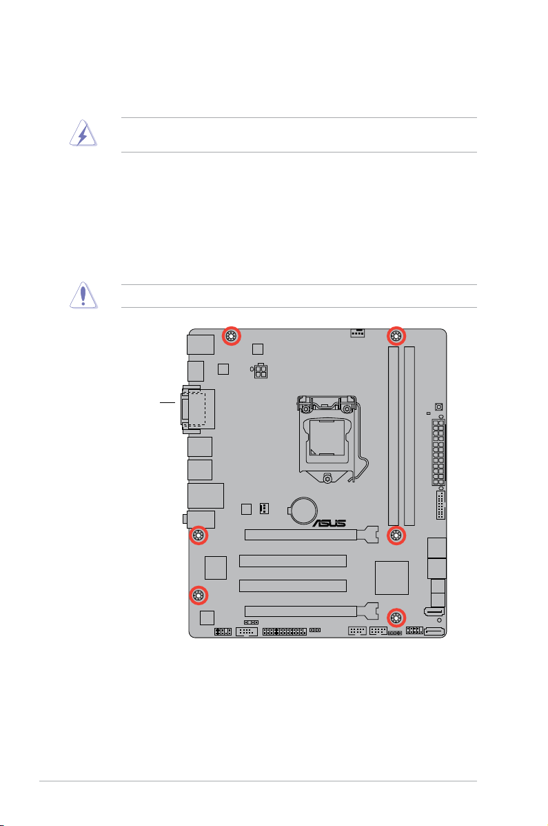
1.5.2 Screw holes
Place six screws into the holes indicated by circles to secure the motherboard to the chassis.
Do not overtighten the screws! Doing so can damage the motherboard.
Place this side towards
the rear of the chassis
ASUS P8B75-M LE Series 1-7
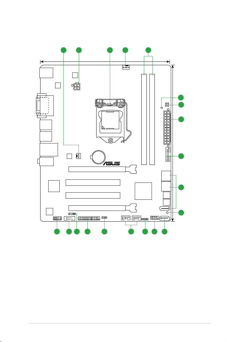
1.5.3 Motherboard layout
P8B75-M LE PLUS
P8B75-M LE PLUS
PCIEX16_1
PCIEX16_2
PCI2
PCI1
AAFP
EATXPWR
CPU_FAN
CHA_FAN
Lithium Cell
CMOS Power
Super
I/O
VIA
VT1708S
DIGI
+VRM
ATX12V
KBMS
64Mb
BIOS
64Mb
BIOS
CLRTC
20.3cm(8.0in)
24.4cm(9.6in)
Intel
®
B75
DDR3 DIMM_A1 (64bit, 240-pin module)
DDR3 DIMM_A2 (64bit, 240-pin module)
SATA6G_1
SATA3G_5
SATA3G_1
SATA3G_2
SATA3G_3
SATA3G_4
AUDIO
USB34
USB3_12
ASM
1442
LAN_USB12
SPDIF_OUT
DVI_VGA
DRAM_LED
MemOK!
LGA1155
USB3_34
F_PANEL
SPEAKER
RTL
8111E
COM1
LPT
USB78 USB56
SB_PWR
1 42 13
1213 101117 16 15 1418
6
2
7
8
9
5
1-8 Chapter 1: Product introduction
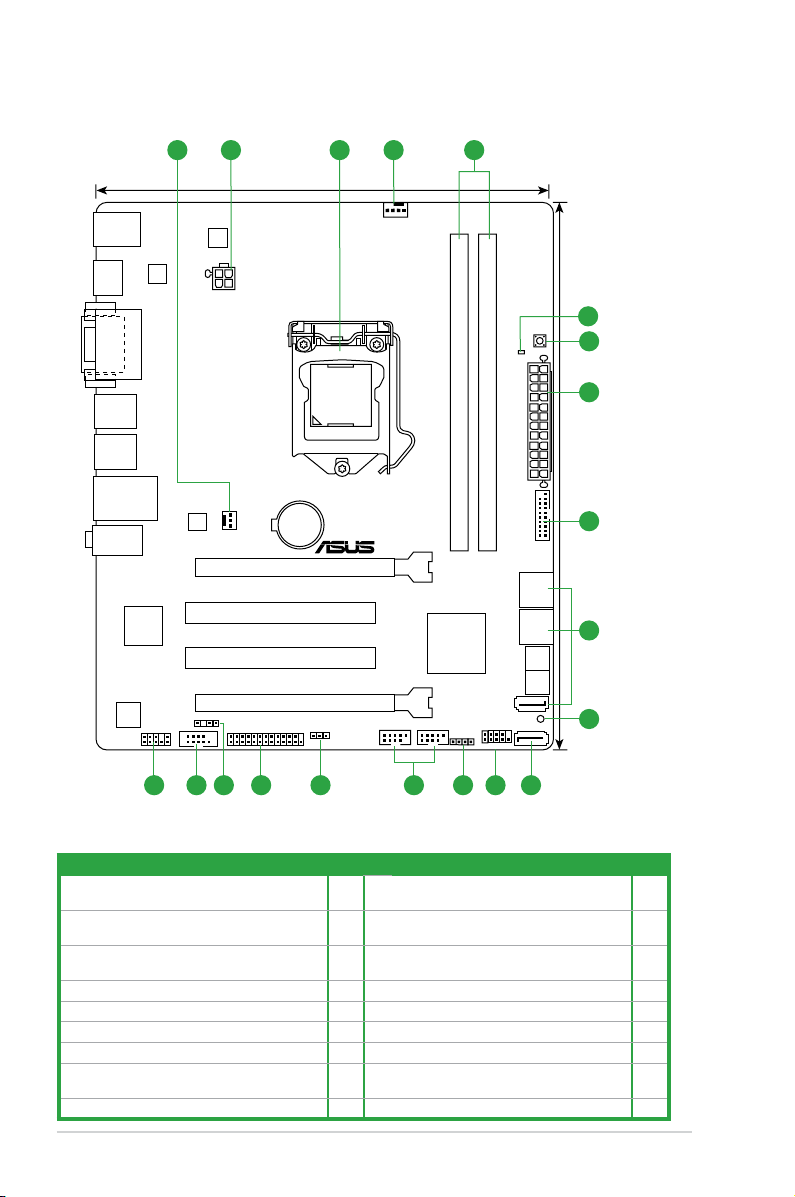
1.5.4 Layout contents
Connectors/Jumpers/Slots/LED Page Connectors/Jumpers/Slots/LED Page
1. CPU and chassis fan connectors (4-pin
CPU_FAN, 3-pin CHA_FAN)
1-26 10. Intel® B75 Serial ATA 6.0Gb/s connectors
(7-pin SATA6G_1 [gray])
1-28
2. ATX power connectors (24-pin EATXPWR,
4-pin ATX12V)
1-25 11. System panel connector (10-1 pin F_PANEL) 1-27
3. Intel® LGA1155 CPU socket 1-9 12. Speaker connector (4-pin SPEAKER) 1-27
4. DDR3 DIMM slots 1-14 13. USB 2.0 connectors (10-1 pin USB56, USB78) 1-29
5. DRAM LED (DRAM_LED) 1-31 14 Clear RTC RAM (3-pin CLRTC) 1-21
6. MemOK! switch 1-30 15. LPT connector (26-1 pin LPT) 1-26
7. USB 3.0 connector (20-1 pin USB3_34) 1-29 16. Digital audio connector (4-1 pin SPDIF_OUT) 1-24
8. Intel® B75 Serial ATA 3.0Gb/s connectors (7-pin
SATA3G_1~5 [blue])
1-28 17. Serial port connector (10-1 pin COM1) 1-25
9. Onboard LED (SB_PWR) 1-31 18 Front panel audio connector (10-1 pin AAFP) 1-24
P8B75-M LE
PCIEX16_1
PCIEX16_2
PCI2
PCI1
AAFP
EATXPWR
CPU_FAN
CHA_FAN
Lithium Cell
CMOS Power
Super
I/O
VIA
VT1708S
DIGI
+VRM
ATX12V
KBMS
HDMI
64Mb
BIOS
64Mb
BIOS
CLRTC
20.3cm(8.0in)
24.4cm(9.6in)
Intel
®
B75
DDR3 DIMM_A1 (64bit, 240-pin module)
DDR3 DIMM_A2 (64bit, 240-pin module)
SATA6G_1
SATA3G_5
SATA3G_1
SATA3G_2
SATA3G_3
SATA3G_4
AUDIO
USB34
USB3_12
ASM
1442
LAN_USB12
SPDIF_OUT
DVI_VGA
DRAM_LED
MemOK!
LGA1155
USB3_34
F_PANEL
SPEAKER
RTL
8111F
COM1
LPT
USB78 USB56
SB_PWR
1 42 13
1213 101117 16 15 1418
6
2
7
8
9
5
ASUS P8B75-M LE Series 1-9
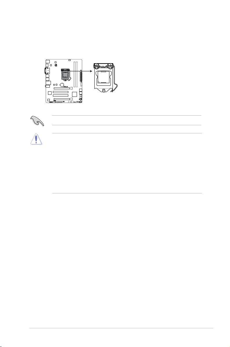
1.6 Central Processing Unit (CPU)
The motherboard comes with a surface mount LGA1155 socket designed for the Intel®
3rd/2nd generation Core™ i7 / Core™ i5 / Core™ i3 processors.
Unplug all power cables before installing the CPU.
• Upon purchase of the motherboard, ensure that the PnP cap is on the socket and the
socket contacts are not bent. Contact your retailer immediately if the PnP cap is missing,
or if you see any damage to the PnP cap/socket contacts/motherboard components.
ASUS will shoulder the cost of repair only if the damage is shipment/transit-related.
• Keep the cap after installing the motherboard. ASUS will process Return Merchandise
Authorization (RMA) requests only if the motherboard comes with the cap on the
LGA1155 socket.
• The product warranty does not cover damage to the socket contacts resulting from
incorrect CPU installation/removal, or misplacement/loss/incorrect removal of the PnP
cap.
Right
P8B75-M LE
P8B75-M LE CPU socket LGA1155
1-10 Chapter 1: Product introduction
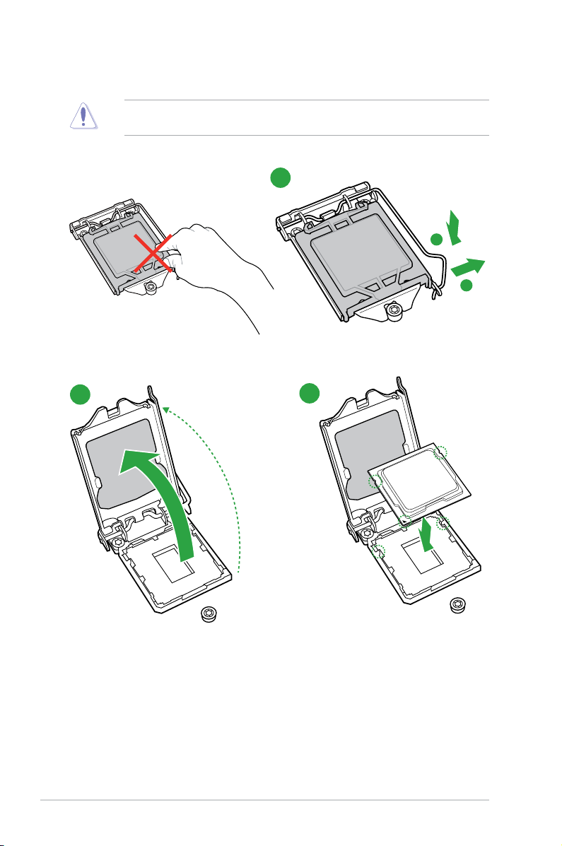
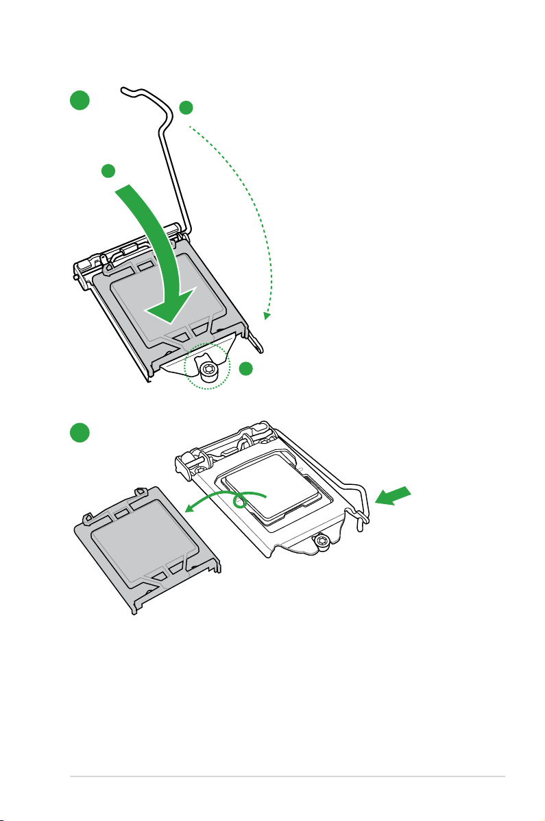
1.6.1 Installing the CPU
1
2
3
The LGA1156 CPU is incompatible with the LGA1155 socket. DO NOT install a LGA1156
CPU on the LGA1155 socket.
ASUS P8B75-M LE Series 1-11

1-12 Chapter 1: Product introduction
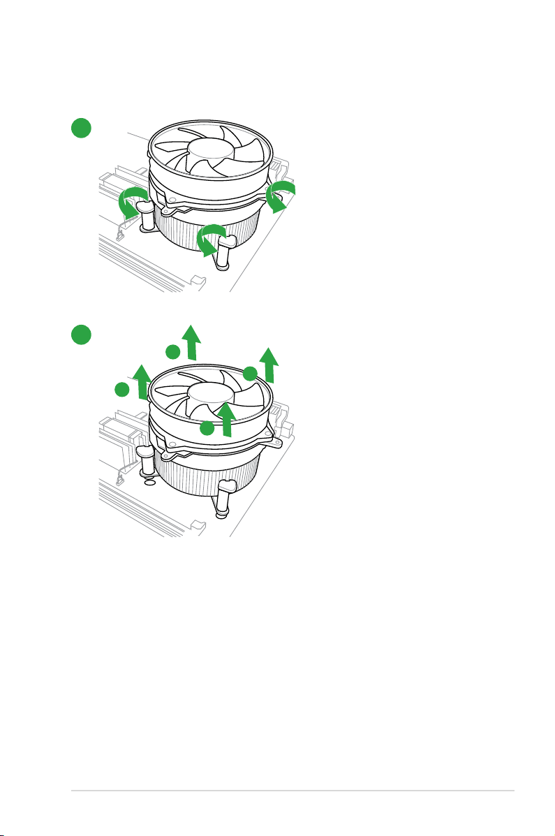
1.6.2 CPU heatsink and fan assembly installation
Apply the Thermal Interface Material
to the CPU heatsink and CPU
before you install the heatsink and
fan if necessary.
To install the CPU heatsink and fan assembly
2
B
A
A
B
3
1
4
ASUS P8B75-M LE Series 1-13
A
B
B
A
To uninstall the CPU heatsink and fan assembly
2
1
1-14 Chapter 1: Product introduction
P8B75-M LE
P8B75-M LE 240-pin DDR3 DIMM sockets
DIMM_A1
DIMM_B1
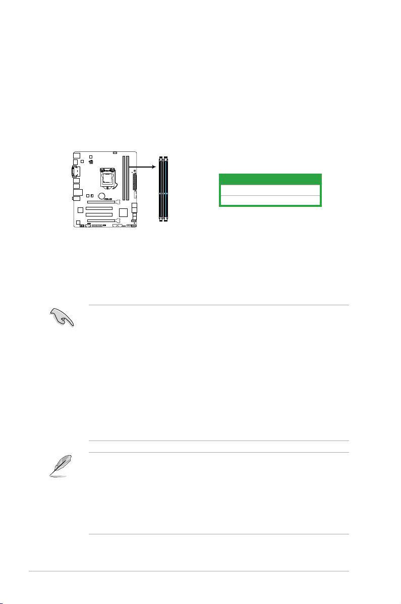
1.7 System memory
1.7.1 Overview
The motherboard comes with four Double Data Rate 3 (DDR3) Dual Inline Memory Modules
(DIMM) sockets. A DDR3 module has the same physical dimensions as a DDR2 DIMM but
is notched differently to prevent installation on a DDR2 DIMM socket. DDR3 modules are
developed for better performance with less power consumption.
The gure illustrates the location of the DDR3 DIMM sockets:
Channel Sockets
Channel A DIMM_A1
Channel B DIMM_B1
1.7.2 Memory congurations
You may install 1GB, 2GB, 4GB and 8GB unbuffered non-ECC DDR3 DIMMs into the DIMM
sockets.
• The default memory operation frequency is dependent on its Serial Presence Detect
(SPD), which is the standard way of accessing information from a memory module.
Under the default state, some memory modules for overclocking may operate at a
lower frequency than the vendor-marked value. To operate at the vendor-marked or at a
higher frequency, refer to section 2.4 Ai Tweaker menu for manual memory frequency
adjustment.
• For system stability, use a more efcient memory cooling system to support a full
memory load (2 DIMMs) or overclocking condition.
• You may install varying memory sizes in Channel A and Channel B. The system maps
the total size of the lower-sized channel for the dual-channel conguration. Any excess
memory from the higher-sized channel is then mapped for single-channel operation.
• Always install DIMMs with the same CAS latency. For optimum compatibility, we
recommend that you obtain memory modules from the same vendor.
• Due to the memory address limitation on 32-bit Windows
®
OS, when you install 4GB
or more memory on the motherboard, the actual usable memory for the OS can be
about 3GB or less. For effective use of memory, we recommend that you do any of the
following:
— Use a maximum of 3GB system memory if you are using a 32-bit Windows
®
OS.
— Install a 64-bit Windows® OS when you want to install 4GB or more on the
motherboard.
• This motherboard does not support DIMMs made up of 512Mb (64MB) chips or less.
Loading…