
Руководства пользователя
Версия T4204
1.97 MB
2009/03/27
Motherboard Installation Guide (Traditional Chinese)
Версия C4204
1.83 MB
2009/03/27
Motherboard Installation Guide (Simplified Chinese)
Версия QJ4204
1.68 MB
2008/10/21
Motherboard Installation Guide (Japanese)
Версия QG4204
1.6 MB
2008/10/21
Motherboard Installation Guide (German)
Версия QF4204
1.59 MB
2008/10/21
Motherboard Installation Guide (French)
Версия Q4204
43.39 MB
2008/10/21
Motherboard Installation Guide (Multiple Languages)
Версия T3241
5.39 MB
2007/07/12
M2N4-SLI user’s manual(Traditional Chinese)
Версия C3241
5.2 MB
2007/07/12
M2N4-SLI user’s manual( Simplified Chinese)
Версия E3241
2.36 MB
2007/07/10
M2N4-SLI user’s manual(English)
Версия —
35.56 KB
2007/05/14
M2N4-SLI Memory QVL
Версия G2670
2.02 MB
2006/10/10
M2N4-SLI User’s Manual for German Edtion(g2670)
Версия j2590
4.26 MB
2006/09/01
M2N4-SLI User’s Manual for Japanese Edtion(j2590)
Версия t2670
5.51 MB
2006/08/30
M2N4-SLI User’s Manual for Traditional Chinese Edtion(T2670)
Версия c2670
5.28 MB
2006/08/30
M2N4-SLI User’s Manual for Simplified Chinese Edtion (C2670)
Версия F2670
3.44 MB
2006/08/09
M2N4-SLI User’s Manual for French Edtion(F2670)
Версия E2670
4.11 MB
2006/08/09
M2N4-SLI English Edition User’s Manual(E2670)
Версия T2437
2.57 MB
2006/05/17
Motherboard DIY Troubleshooting Guide (Traditional Chinese version)

M2N4-SLI
Motherboard

E2670
First Edition
July 2006
Copyright © 2006 ASUSTeK COMPUTER INC. All Rights Reserved.
No part of this manual, including the products and software described in it, may be reproduced,
transmitted, transcribed, stored in a retrieval system, or translated into any language in any form
or by any means, except documentation kept by the purchaser for backup purposes, without the
express written permission of ASUSTeK COMPUTER INC. (“ASUS”).
Product warranty or service will not be extended if: (1) the product is repaired, modied or
altered, unless such repair, modication of alteration is authorized in writing by ASUS; or (2)
the serial number of the product is defaced or missing.
ASUS PROVIDES THIS MANUAL “AS IS” WITHOUT WARRANTY OF ANY KIND, EITHER
EXPRESS OR IMPLIED, INCLUDING BUT NOT LIMITED TO THE IMPLIED WARRANTIES
OR CONDITIONS OF MERCHANTABILITY OR FITNESS FOR A PARTICULAR PURPOSE.
IN NO EVENT SHALL ASUS, ITS DIRECTORS, OFFICERS, EMPLOYEES OR AGENTS BE
LIABLE FOR ANY INDIRECT, SPECIAL, INCIDENTAL, OR CONSEQUENTIAL DAMAGES
(INCLUDING DAMAGES FOR LOSS OF PROFITS, LOSS OF BUSINESS, LOSS OF USE
OR DATA, INTERRUPTION OF BUSINESS AND THE LIKE), EVEN IF ASUS HAS BEEN
ADVISED OF THE POSSIBILITY OF SUCH DAMAGES ARISING FROM ANY DEFECT OR
ERROR IN THIS MANUAL OR PRODUCT.
SPECIFICATIONS AND INFORMATION CONTAINED IN THIS MANUAL ARE FURNISHED
FOR INFORMATIONAL USE ONLY, AND ARE SUBJECT TO CHANGE AT ANY TIME
WITHOUT NOTICE, AND SHOULD NOT BE CONSTRUED AS A COMMITMENT BY
ASUS. ASUS ASSUMES NO RESPONSIBILITY OR LIABILITY FOR ANY ERRORS OR
INACCURACIES THAT MAY APPEAR IN THIS MANUAL, INCLUDING THE PRODUCTS
AND SOFTWARE DESCRIBED IN IT.
Products and corporate names appearing in this manual may or may not be registered
trademarks or copyrights of their respective companies, and are used only for identication or
explanation and to the owners’ benet, without intent to infringe.
ii

Contents
Notices ……………………………………………………………………………………vii
Safety information …………………………………………………………………..viii
About this guide ………………………………………………………………………. ix
Typography ……………………………………………………………………………… x
M2N4-SLI specications summary………………………………………………. xi
Chapter 1: Product introduction
1.1 Welcome! …………………………………………………………………… 1-1
1.2 Package contents ………………………………………………………..
1.3 Special features …………………………………………………………..
1.3.1 Product highlights ……………………………………………
1.3.2 ASUS Special features ………………………………………
Chapter 2: Hardware information
2.1 Before you proceed …………………………………………………….. 2-1
2.2 Motherboard overview ………………………………………………….
2.2.1 Placement direction …………………………………………
2.2.2 Screw holes …………………………………………………….
2.2.3 Motherboard layout …………………………………………
2.2.4 Layout Contents ……………………………………………..
2.3 Central Processing Unit (CPU) ……………………………………….
2.3.1 Installing the CPU …………………………………………….
2.3.2 Installing the heatsink and fan …………………………..
2.4 System memory …………………………………………………………
2.4.1 Overview ………………………………………………………
2.4.2 Memory congurations …………………………………..
2.4.3 Installing a DIMM ……………………………………………
2.4.4 Removing a DIMM …………………………………………..
2.5 Expansion slots ………………………………………………………….
2.5.1 Installing an expansion card …………………………….
2.5.2 Conguring an expansion card …………………………
2.5.3 Interrupt assignments …………………………………….
2.5.4 PCI slots ……………………………………………………….
2.5.5 PCI Express x1 slot ………………………………………..
2.5.6 PCI Express x16 slots ……………………………………..
1-1
1-2
1-2
1-4
2-2
2-2
2-2
2-3
2-4
2-5
2-5
2-7
2-10
2-10
2-10
2-15
2-15
2-16
2-16
2-16
2-17
2-17
2-18
2-18
iii

Contents
2.6 Jumpers …………………………………………………………………… 2-19
2.7 Connectors ……………………………………………………………….
2.7.1 Rear panel connectors ……………………………………
2.7.2 Internal connectors ………………………………………..
Chapter 3: Powering up
3.1 Starting up for the rst time ………………………………………… 3-1
3.2 Powering off the computer ……………………………………………
3.2.1 Using the OS shut down function ………………………
3.2.2 Using the dual function power switch …………………
Chapter 4: BIOS setup
4.1 Managing and updating your BIOS …………………………………. 4-1
4.1.1 Creating a bootable oppy disk …………………………
4.1.2 Updating the BIOS ……………………………………………
4.1.3 Saving the current BIOS le ………………………………
4.1.4 ASUS CrashFree BIOS 3 utility …………………………..
4.1.5 ASUS EZ Flash 2 utility ……………………………………..
4.1.6 ASUS Update utility …………………………………………
4.2 BIOS setup program ……………………………………………………
4.2.1 BIOS menu screen ………………………………………….
4.2.2 Menu bar ………………………………………………………
4.2.3 Legend bar ……………………………………………………
4.2.4 Menu items …………………………………………………..
4.2.5 Sub-menu items …………………………………………….
4.2.6 Conguration elds ………………………………………..
4.2.7 Pop-up window ………………………………………………
4.2.8 General help ………………………………………………….
4.3 Main menu …………………………………………………………………
4.3.1 System Time ………………………………………………..
4.3.2 System Date ………………………………………………..
4.3.3 Legacy Diskette A ………………………………………..
4.3.5 Primary and Secondary IDE Master/Slave ………….
4.3.6 SATA 1, 2, 3, 4 ……………………………………………..
4.3.7 HDD SMART Monitoring …………………………………..
2-22
2-22
2-24
3-2
3-2
3-2
4-1
4-2
4-4
4-5
4-7
4-8
4-11
4-12
4-12
4-13
4-13
4-13
4-13
4-14
4-14
4-15
4-15
4-15
4-15
4-16
4-18
4-19
iv

Contents
4.3.8 Installed Memory …………………………………………… 4-19
4.4 Advanced menu …………………………………………………………
4.4.1 JumperFree Conguration ……………………………….
4.4.3 CPU Conguration ………………………………………….
4.4.4 PCIPnP ………………………………………………………….
4.4.5 Onboard Device Conguration …………………………
4.4.6 SLI Conguration ……………………………………………
4.5 Power menu ………………………………………………………………
4.5.1 ACPI Suspend Type ……………………………………….
4.5.2 ACPI APIC Support ………………………………………..
4.5.3 APM Conguration …………………………………………
4.5.4 Hardware Monitor …………………………………………..
4.6 Boot menu ………………………………………………………………..
4.6.1 Boot Device Priority ……………………………………….
4.6.2 Removable Drives …………………………………………..
4.6.3 Hard Disk Drives …………………………………………….
4.6.4 Boot Settings Conguration …………………………..
4.6.5 Security ………………………………………………………..
4.7 Tools menu ……………………………………………………………….
ASUS EZ Flash 2 ………………………………………………………… 4-43
4.8 Exit menu ………………………………………………………………….
4-20
4-20
4-23
4-25
4-26
4-31
4-32
4-32
4-32
4-33
4-35
4-37
4-37
4-38
4-38
4-39
4-41
4-43
4-44
Chapter 5: Software support
5.1 Installing an operating system ………………………………………. 5-1
5.2 Support CD information ………………………………………………..
5.2.1 Running the support CD ……………………………………
5.2.2 Drivers menu …………………………………………………..
5.2.3 Utilities menu ………………………………………………….
5.2.4 Manuals menu …………………………………………………
5.2.5 ASUS Contact information ………………………………..
5.2.6 Other information ……………………………………………
5.3 Software information ……………………………………………………
5.3.1 Cool ‘n’ Quiet!™ Technology ……………………………..
5.3.2 ASUS PC Probe II ……………………………………………
5.4 RAID congurations ……………………………………………………
5-1
5-1
5-2
5-3
5-4
5-5
5-5
5-8
5-8
5-10
5-16
v

Contents
5.4.1 Installing hard disks ……………………………………….. 5-17
®
5.4.2 NVIDIA
5.5 Creating a RAID driver disk ………………………………………….
Chapter 6: NVIDIA® SLI™ technology support
6.1 Overview ……………………………………………………………………. 6-1
Requirements ……………………………………………………………… 6-1
6.2 Dual graphics card setup ………………………………………………
6.2.1 Installing SLI-ready graphics cards ……………………..
6.2.2 Installing the device drivers ………………………………
6.2.3 Enabling the multi-GPU feature in Windows …………
RAID congurations …………………………… 5-18
5-25
6-2
6-2
6-5
6-5
vi
Notices
Federal Communications Commission Statement
This device complies with Part 15 of the FCC Rules. Operation is subject to
the following two conditions:
•
This device may not cause harmful interference, and
•
This device must accept any interference received including
interference that may cause undesired operation.
This equipment has been tested and found to comply with the limits for a
Class B digital device, pursuant to Part 15 of the FCC Rules. These limits
are designed to provide reasonable protection against harmful interference
in a residential installation. This equipment generates, uses and can radiate
radio frequency energy and, if not installed and used in accordance with
manufacturer’s instructions, may cause harmful interference to radio
communications. However, there is no guarantee that interference will
not occur in a particular installation. If this equipment does cause harmful
interference to radio or television reception, which can be determined by
turning the equipment off and on, the user is encouraged to try to correct
the interference by one or more of the following measures:
•
Reorient or relocate the receiving antenna.
•
Increase the separation between the equipment and receiver.
•
Connect the equipment to an outlet on a circuit different from that to
which the receiver is connected.
•
Consult the dealer or an experienced radio/TV technician for help.
The use of shielded cables for connection of the monitor to the graphics
card is required to assure compliance with FCC regulations. Changes
or modications to this unit not expressly approved by the party
responsible for compliance could void the user’s authority to operate
this equipment.
Canadian Department of Communications Statement
This digital apparatus does not exceed the Class B limits for radio noise
emissions from digital apparatus set out in the Radio Interference
Regulations of the Canadian Department of Communications.
This class B digital apparatus complies with Canadian
ICES-003.
vii

Safety information
Electrical safety
•
To prevent electrical shock hazard, disconnect the power cable from
the electrical outlet before relocating the system.
•
When adding or removing devices to or from the system, ensure that
the power cables for the devices are unplugged before the signal cables
are connected. If possible, disconnect all power cables from the existing
system before you add a device.
•
Before connecting or removing signal cables from the motherboard,
ensure that all power cables are unplugged.
•
Seek professional assistance before using an adapter or extension cord.
These devices could interrupt the grounding circuit.
•
Make sure that your power supply is set to the correct voltage in your
area. If you are not sure about the voltage of the electrical outlet you
are using, contact your local power company.
•
If the power supply is broken, do not try to x it by yourself. Contact a
qualied service technician or your retailer.
Operation safety
•
Before installing the motherboard and adding devices on it, carefully
read all the manuals that came with the package.
•
Before using the product, make sure all cables are correctly connected
and the power cables are not damaged. If you detect any damage,
contact your dealer immediately.
•
To avoid short circuits, keep paper clips, screws, and staples away from
connectors, slots, sockets and circuitry.
•
Avoid dust, humidity, and temperature extremes. Do not place the
product in any area where it may become wet.
•
Place the product on a stable surface.
•
If you encounter technical problems with the product, contact a
qualied service technician or your retailer.
viii
The symbol of the crossed out wheeled bin indicates that the product
(electrical and electronic equipment) should not be placed in municipal
waste. Check local regulations for disposal of electronic products.

About this guide
This user guide contains the information you need when installing and
conguring the motherboard.
How this guide is organized
This manual contains the following parts:
• Chapter 1: Product introduction
This chapter describes the features of the motherboard and the new
technology it supports.
• Chapter 2: Hardware information
This chapter lists the hardware setup procedures that you have to
perform when installing system components. It includes description of
the switches, jumpers, and connectors on the motherboard.
• Chapter 3: Powering up
This chapter describes the power up sequence, the vocal POST
messages, and ways of shutting down the system.
• Chapter 4: BIOS setup
This chapter tells how to change system settings through the BIOS
Setup menus. Detailed descriptions of the BIOS parameters are also
provided.
• Chapter 5: Software support
This chapter describes the contents of the support CD that comes
with the motherboard package.
®
• Chapter 6: NVIDIA
This chapter tells how to install SLI-ready PCI Express graphics cards.
SLI™ technology support
ix
Where to nd more information
Refer to the following sources for additional information and for product
and software updates.
1. ASUS websites
The ASUS website provides updated information on ASUS hardware
and software products. Refer to the ASUS contact information.
2. Optional documentation
Your product package may include optional documentation, such as
warranty yers, that may have been added by your dealer. These
documents are not part of the standard package.
Conventions used in this guide
To make sure that you perform certain tasks properly, take note of the
following symbols used throughout this manual.
DANGER/WARNING: Information to prevent injury to yourself
when trying to complete a task.
CAUTION: Information to prevent damage to the components
when trying to complete a task.
IMPORTANT: Instructions that you MUST follow to complete a
task.
NOTE: Tips and additional information to help you complete a
task.
Typography
Bold text Indicates a menu or an item to select
Italics
Used to emphasize a word or a phrase
<Key> Keys enclosed in the less-than and greater-than sign means
that you must press the enclosed key
Example: <Enter> means that you must press the Enter or
Return key
<Key1>+<Key2>+<Key3> If you must press two or more keys simultaneously, the
key names are linked with a plus sign (+)
Example: <Ctrl>+<Alt>+<D>
Command Means that you must type the command exactly as shown,
then supply the required item or value enclosed in
brackets
Example: At the DOS prompt, type the command line:
awdash M2N4SLI.ROM
x
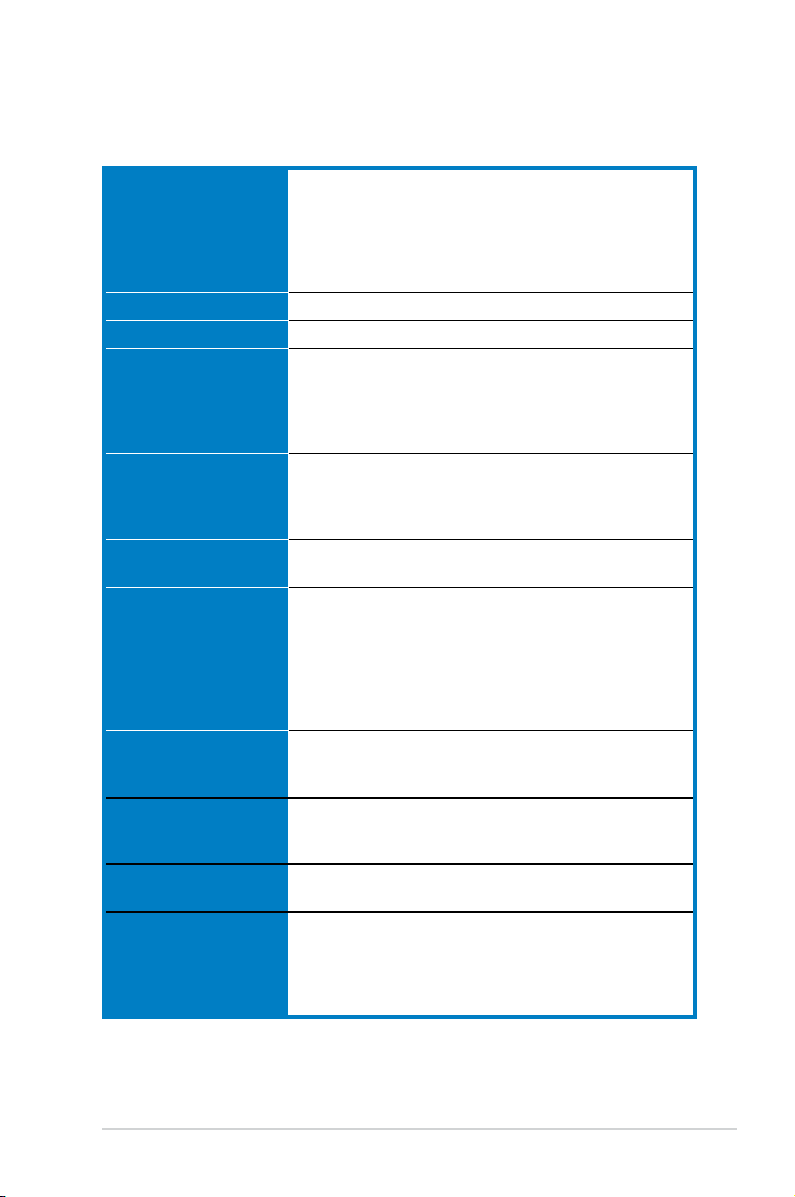
M2N4-SLI specications summary
CPU Socket AM2 for AMD Athlon™ 64 FX/AMD Athlon™ 64 X2
/AMD Athlon 64™/AMD Sempron™ processors
Supports AMD Cool ‘n’ Quiet™ Technology
AMD64 architecture enables simultaneous 32-bit and
64-bit computing
AMD Live!™ ready
Chipset NVIDIA
®
nForce® 4 SLI™ MCP
System bus 2000 / 1600 MT/s
Memory Dual-channel memory architecture
— 4 x 240-pin DIMM sockets support unbuffered
ECC/non-ECC DDR2 800/667/533 MHz memory
modules
— Supports up to 8 GB system memory
Expansion slots 2 x PCI Express™ x16 slots
Supports NVIDIA® SLI™ Technology (both at x8 mode)
2 x PCI Express™ x1 slots
2 x PCI 2.2 slots
Scalable Link Interface
(SLI™)
Supports two identical NVIDIA
ASUS two-slot thermal design
Storage NVIDIA® nForce
®
4 SLI™ MCP supports:
®
SLI™-ready graphics card
— 2 x IDE connector for up to four Ultra DMA
133/100/66/33 devices
— 4 x Serial ATA 3.0 Gb/s connectors support four
Serial ATA devices
— RAID 0, RAID 1, RAID 0+1, RAID 5, and JBOD
congurations spanning across Serial ATA drives
LAN NVIDIA® nForce
®
4 SLI™ MCP built-in Gigabit MAC with
external Attansic PHY
Supports TCP/IP Acceleration
Audio Realtek® ALC850 6-channel AC’97 CODEC
Supports Jack-Sensing and Enumeration Technology
Supports S/PDIF Out interface
USB 2.0 Supports up to 10 USB 2.0/1.1 ports (six at mid-board,
four on the rear panel)
ASUS Exclusive
Overclocking features
AI Overclocking (intelligent CPU frequency tuner)
Stepless Frequency Selection(SFS) allows FSB tuning
from 200 MHz up to 400 MHz at 1 MHz increment
ASUS C.P.R. (CPU Parameter Recall)
Adjustable FSB/DDR2 ratio. Fixed PCI/PCIe frequencies
(continued on the next page)
xi
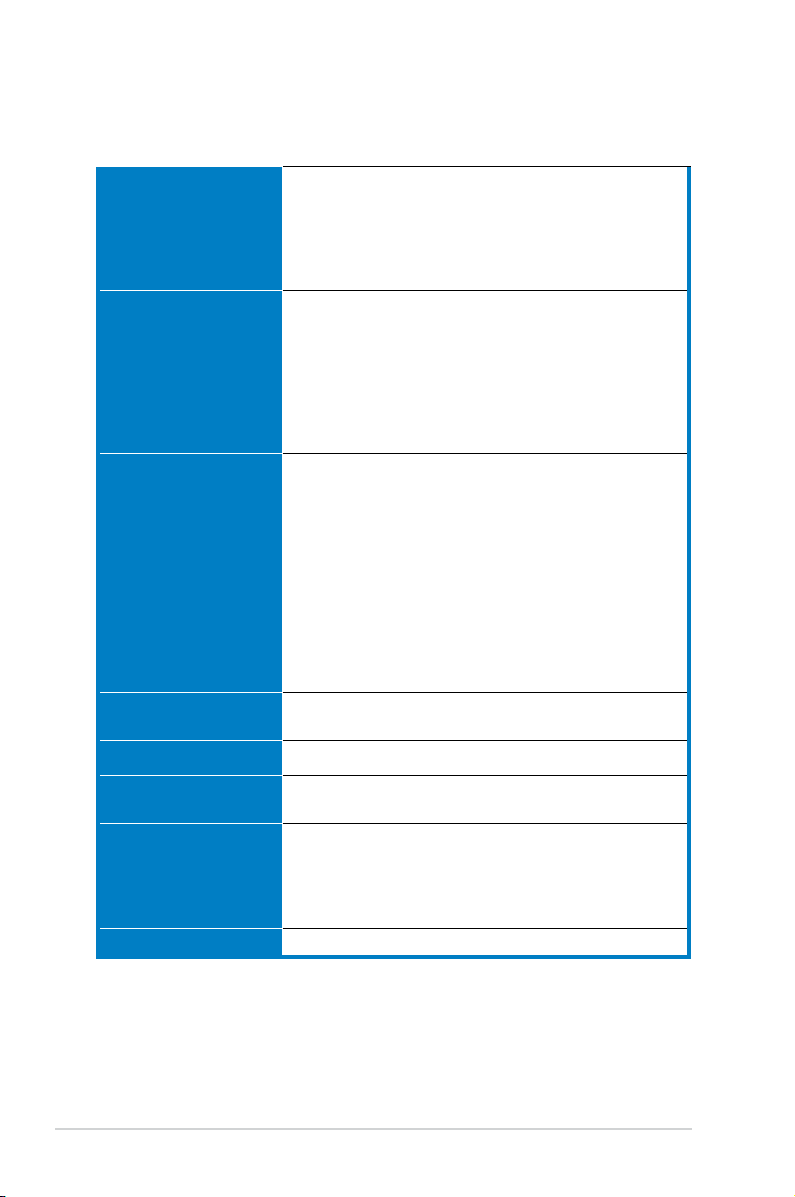
M2N4-SLI specications summary
Special features ASUS EZ DIY:
Rear panel 1 x Parallel port
Internal connectors 3 x USB 2.0 connectors support six additional USB 2.0
BIOS features 4 Mb BIOS ROM, AWARD BIOS, PnP, DMI 2.0, WfM2.0,
Manageability WOL by PME, WOR by PME, Chassis intrusion, PXE
— Q-Connector
— ASUS CrashFree BIOS 3
— ASUS EZ Flash 2
ASUS Q-Fan 2
ASUS MyLogo2
1 x PS/2 keyboard port (purple)
1 x PS/2 mouse port (green)
1 x Serial (COM1) port
1 x Coaxial S/PDIF Out port
1 x LAN (RJ-45) ports
4 x USB 2.0/1.1 ports
6-channel audio ports
ports
1 x Floppy disk drive connector
2 x IDE connector for four devices
4 x Serial ATA connectors
1 x CPU / 1 x Chassis / 1 x Power fan connectors
S/PDIF out connector
Front panel audio connector
CD/AUX audio in connectors
24-pin ATX power connector
4-pin ATX 12 V power connector
System panel connector
SM BIOS 2.3
Power requirements ATX power supply with 24-pin and 4-pin 12V plugs
Support CD contents Device drivers
Form factor ATX form factor: 12 in x 9 in (30.5 cm x 22.8 cm)
*Specications are subject to change without notice.
xii
ATX 12V 2.0 compliant
ASUS PC Probe II
ASUS Update
NVIDIA® MediaShield™ RAID
Anti-virus software (OEM version)

This chapter describes the motherboard
features and the new technologies
it supports.
introduction
Product
1

Chapter summary
1.1 Welcome! …………………………………………………………………… 1-1
1.2 Package contents ………………………………………………………..
1.3 Special features …………………………………………………………..
1-1
1-2
ASUS M2N4-SLI
1.1 Welcome!
Thank you for buying an ASUS
The motherboard delivers a host of new features and latest technologies,
making it another standout in the long line of ASUS quality motherboards!
Before you start installing the motherboard, and hardware devices on it,
check the items in your package with the list below.
®
M2N4-SLI motherboard!
1.2 Package contents
Check your motherboard package for the following items.
Motherboard ASUS M2N4-SLI motherboard
Cables 2 x Serial ATA signal cables
1 x Serial ATA power cable with dual plugs
1 x Ultra DMA/133 cable
1 x Floppy disk drive cable
Accessories I/O shield
ASUS SLI™ bridge
1 x ASUS Q-Connector Kit
(USB, System panel; Retail version only)
Application CDs ASUS motherboard support CD
Documentation User guide
If any of the above items is damaged or missing, contact your retailer.
ASUS M2N4-SLI 1-1
1.3 Special features
1.3.1 Product highlights
Latest processor technology
The motherboard comes with a 940-pin AM2 socket that supports AMD
Athlon™ 64 X2/AMD Athlon™ 64/AMD Athlon™ 64 FX/AMD Sempron™
processors. With an integrated low-latency high-bandwidth memory
controller and a highly scalable HyperTransport™ technology-based system
bus, the motherboard provides a powerful platform for your diverse
computing needs, increased ofce productivity, and enhanced digital media
experience. See page 2-5 for details.
Scalable Link Interface (SLI™) technology
The NVIDIA® nForce4® Scalable Link Interface (SLI™) technology allows two
graphics processing units (GPUs) in a single system. This technology takes
advantage of the PCI Express™ bus architecture and features intelligent
hardware and software solutions that allows multiple GPUs to work
together and achieve exceptional graphics performance. See Chapter 6 for
details.
AMD Cool ‘n’ Quiet!™ Technology
The motherboard supports the AMD Cool ‘n’ Quiet!™ Technology that
dynamically and automatically changes the CPU speed, voltage and amount
of power depending on the task the CPU performs. See pages 4-25, 5-3
and 5-9.
Gigabit LAN
The motherboard comes with a Gigabit LAN controller built into the
NVIDIA® nForce™4 chipset to meet your growing networking needs. The
controller uses the PCI Express segment to provide faster data bandwidth
for your Internet, LAN, and le sharing requirements. See page 2-22 for
details.
DDR2 memory support
The motherboard supports DDR2 memory that features data transfer rates
of 800/667/533 MHz to meet the higher bandwidth requirements of the
latest 3D graphics, multimedia, and Internet applications. The dual-channel
DDR2 architecture doubles the bandwidth of your system memory to boost
system performance, eliminating bottlenecks with peak bandwidths of up
to 12.8 GB/s. See pages 2-10 to 2-13 for details.
1-2 Chapter 1: Product introduction

Serial ATA 3Gb/s RAID
The motherboard supports the next-generation Serial ATA hard drives
based on the SATA 3Gb/s storage specication. The onboard NVIDIA
nForce® 4 SLI™ MCP allows RAID 0, RAID 1, RAID 0+1, RAID 5, and JBOD.
See page 2-25.
PCI Express™ interface
The motherboard fully supports PCI Express, the latest I/O interconnect
technology that speeds up the PCI bus. PCI Express features point-to-point
serial interconnections between devices and allows higher clockspeeds by
carrying data in packets. This high speed interface is software compatible
with existing PCI specications. See page 2-18 for details.
S/PDIF digital sound ready
The motherboard supports the S/PDIF Out function through the S/PDIF
interfaces on the rear panel. The S/PDIF technology turns your computer
into a high-end entertainment system with digital connectivity to powerful
audio and speaker systems. See page 2-23 for details.
USB 2.0 technology
The motherboard implements the Universal Serial Bus (USB) 2.0
specication, dramatically increasing the connection speed from the
12 Mbps bandwidth on USB 1.1 to a fast 480 Mbps on USB 2.0. USB 2.0 is
backward compatible with USB 1.1. See page 2-23 and 2-27 for details.
ASUS M2N4-SLI 1-3
1.3.2 ASUS Special features
ASUS Two-slot thermal design
The motherboard is designed with two PCI Express x1 slots placed between
the PCI Express x16 slots allowing an increase in airow between the two
PCI Express x16 graphics cards. This special design permits more room for
ventilation thus lowering the overall system temperature.
ASUS CrashFree BIOS 3
The ASUS CrashFree BIOS 3 allows users to restore corrupted BIOS data
from a USB ash disk containing the BIOS le. This utility saves users
the cost and hassle of buying a replacement BIOS chip. See page 4-5 for
details.
ASUS EZ Flash 2
EZ Flash 2 is a user-friendly BIOS update utility. Simply press the predened
hotkey to launch the utility and update the BIOS without entering the OS.
Update your BIOS easily without preparing a bootable diskette or using an
OS-based ash utility. See page 4-7 for details.
ASUS Q-Connector
ASUS Q-Connector allows you to easily connect or disconnect the chassis
front panel cables to the motherboard. This unique module eliminates the
trouble of connecting the system panel cables one at a time and avoiding
wrong cable connections.
ASUS Q-Fan 2 technology
The ASUS Q-Fan technology smartly adjusts the CPU and chassis fan
speeds according to the system loading to ensure quiet, cool, and efcient
operation. See page 4-35 for details.
ASUS MyLogo2™
This new feature present in the motherboard allows you to personalize and
add style to your system with customizable boot logos.
1-4 Chapter 1: Product introduction

This chapter lists the hardware setup
procedures that you have to perform
when installing system components.
It includes description of the jumpers
and connectors on the motherboard.
information
Hardware
2

Chapter summary
2.1 Before you proceed …………………………………………………….. 2-1
2.2 Motherboard overview ………………………………………………….
2.3 Central Processing Unit (CPU) ……………………………………….
2.4 System memory …………………………………………………………
2.5 Expansion slots ………………………………………………………….
2.6 Jumpers ……………………………………………………………………
2.7 Connectors ……………………………………………………………….
2-2
2-5
2-10
2-16
2-19
2-22
ASUS M2N4-SLI

2.1 Before you proceed
R
M2N4-SLI
M2N4-SLI Onboard LED
SB_PWR
ON
Standby
Power
OFF
Powered
Off
Take note of the following precautions before you install motherboard
components or change any motherboard settings.
• Make sure that your power supply unit (PSU) can provide at least
the minimum power required by your system. See “8. ATX power
connectors” on page 2-26 for details.
• Unplug the power cord from the wall socket before touching any
component.
• Use a grounded wrist strap or touch a safely grounded object or
to a metal object, such as the power supply case, before handling
components to avoid damaging them due to static electricity
• Hold components by the edges to avoid touching the ICs on them.
• Whenever you uninstall any component, place it on a grounded
antistatic pad or in the bag that came with the component.
• Before you install or remove any component, ensure that the ATX
power supply is switched off or the power cord is detached from
the power supply. Failure to do so may cause severe damage to the
motherboard, peripherals, and/or components.
Onboard LED
The motherboard comes with a standby power LED that lights up to
indicate that the system is ON, in sleep mode, or in soft-off mode.
This is a reminder that you should shut down the system and unplug
the power cable before removing or plugging in any motherboard
component. The illustration below shows the location of the onboard
LED.
ASUS M2N4-SLI 2-1
2.2 Motherboard overview
Before you install the motherboard, study the conguration of your chassis
to ensure that the motherboard ts into it.
Make sure to unplug the power cord before installing or removing the
motherboard. Failure to do so can cause you physical injury and damage
motherboard components.
2.2.1 Placement direction
When installing the motherboard, make sure that you place it into the
chassis in the correct orientation. The edge with external ports goes to the
rear part of the chassis as indicated in the image below.
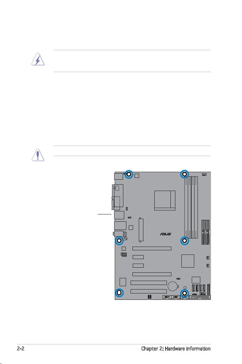
2.2.2 Screw holes
Place six (6) screws into the holes indicated by circles to secure the
motherboard to the chassis.
Do not overtighten the screws! Doing so can damage the motherboard.
Place this side towards
the rear of the chassis
2-2 Chapter 2: Hardware information
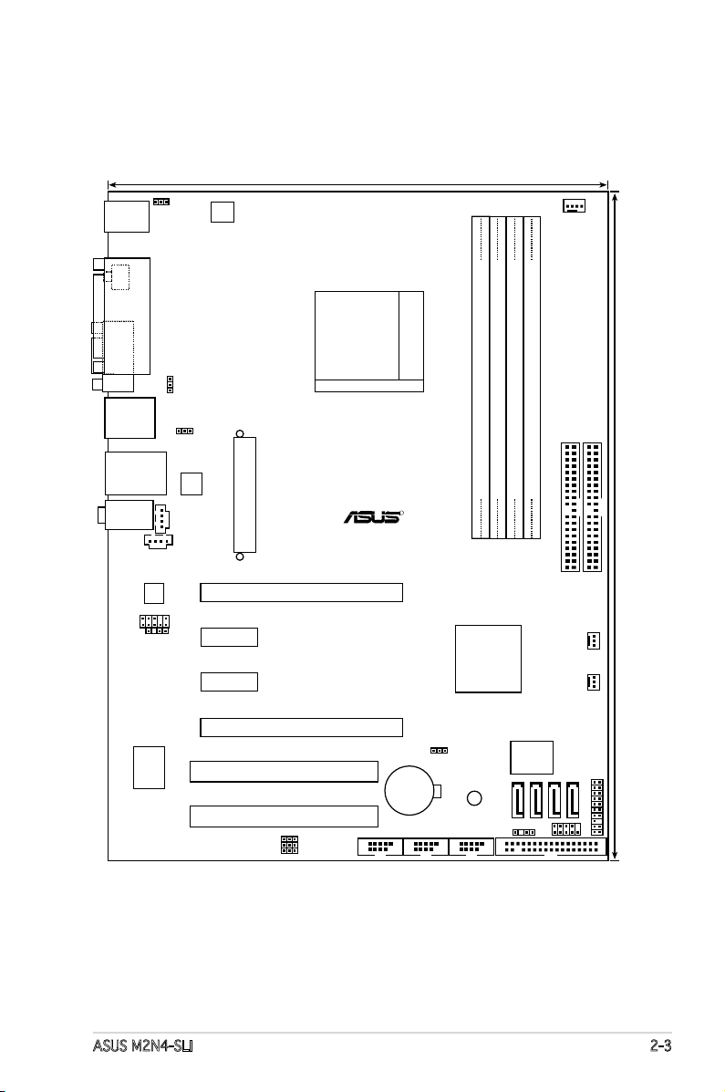
Socket AM2
Super I/O
R
M2N4-SLI
CR2032 3V
SB_PWR
Lithium Cell
CMOS Power
ATX12V
KBPWR
23.0cm (9.0in)
30.5cm (12.0in)
PANEL
CPU_FAN
PS/2KBMS
T: Mouse
B: Keyboard
PARALLEL PORT
COM1
SPDIF_O1
PRI_IDE
SEC_IDE
USBPW56
USBPW78
USBPW910
USB910
FLOPPY
USB78USB56
SATA4
SATA3
SATA2
SATA1
CLRTC
CHASSIS
F_PANEL
USBPW34
NVIDIA NF4 SLI
CHA_FAN PWR_FAN
USB12
LAN_USB34
FP_AUDIO
SPDIF_OUT
USBPW12
CD
AUX
PCIEX16_1
PCIEX1_1
PCIEX1_2
PCIEX16_2
PCI1
PCI2
DDR2 DIMM_A1 (64 bit,240-pin module)
DDR2 DIMM_B1 (64 bit,240-pin module)
DDR2 DIMM_A2 (64 bit,240-pin module)
DDR2 DIMM_B2 (64 bit,240-pin module)
EATXPWR
AUDIO
Attansic
F1
ALC850
4Mb
BIOS
2.2.3 Motherboard layout
ASUS M2N4-SLI 2-3
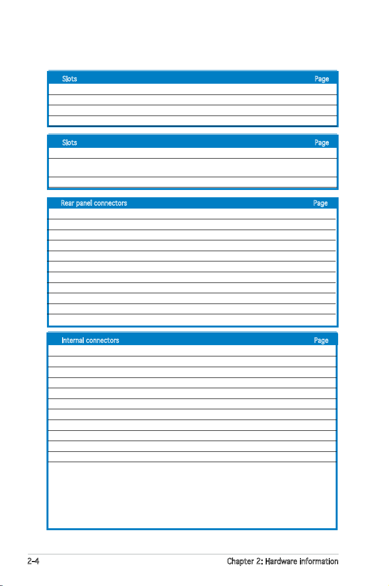
2.2.4 Layout Contents
Slots Page
1. DDR2 DIMM slots 2-10
2. PCI slots 2-17
3. PCI Express x16 slot 2-18
4. PCI Express x1 slot 2-18
Slots Page
1. CLRTC (3-pin CLRTC1) 2-19
2. USB device wake-up (3-pin USBPW12, USBPW34, USBPW56,
USBPW78, USBPW910) 2-20
3. Keyboard Power (3-pin KBPWR) 2-21
Rear panel connectors Page
1. PS/2 mouse port (green) 2-22
2. Parallel port 2-22
3. Serial (COM) port 2-22
4. LAN (RJ-45) port 2-22
5. Line In port (light blue) 2-22
6. Microphone port (pink) 2-22
7. Line Out port (lime) 2-22
8. USB 2.0 ports 3 and 4 2-23
9. USB 2.0 ports 1 and 2 2-23
10. Coaxial S/PDIF out port 2-23
11. PS/2 keyboard port (purple) 2-23
Internal connectors Page
1. Floppy disk drive connector (34-1 pin FLOPPY) 2-23
2. Primary/Secondary IDE connector (40-1 pin PRI_IDE, SEC_IDE) 2-24
3. nForce 4 Serial ATA connectors (7-pin SATA1, SATA2, SATA3, SATA4) 2-25
4. CPU fan connector (3-pin CPU_FAN) 2-26
5. Power fan connector (3-pin PWR_FAN) 2-26
6. Chassis fan connector (3-pin CHA_FAN) 2-26
7. USB headers (10-1 USB56, USB78, USB910) 2-27
8. ATX power connector (24-pin EATXPWR1) 2-28
9. ATX 12V power connector (4-pin ATX12V1) 2-28
10. Internal audio connectors (4-pin CD/AUX) 2-29
11. Front panel audio connector (10-1 pin FP_AUDIO) 2-29
12. System panel connector (20-8 pin PANEL) 2-30
•
System power LED (2-pin LED)
•
Hard disk drive activity LED (2-pin IDE_LED)
•
System warning speaker (4-pin SPEAKER)
•
ATX power button/soft-off button (2-pin PWR)
•
Reset button (2-pin RESET)
2-4 Chapter 2: Hardware information

2.3 Central Processing Unit (CPU)
R
M2N4-SLI
M2N4-SLI CPU Socket AM2
The motherboard comes with a 940-pin AM2 socket designed for the AMD
Athlon™ 64 X2/AMD Athlon™ 64 FX/AMD Athlon™ 64 and AMD Sempron™
processors.
Make sure you use a CPU is designed for the AM2 socket. The CPU ts in
only one correct orientation. DO NOT force the CPU into the socket to
prevent bending the connectors on the socket and damaging the CPU!
2.3.1 Installing the CPU
To install a CPU:
1. Locate the CPU socket on the motherboard.
2. Unlock the socket by pressing
the lever sideways, then lift it up
to a 90º angle.
ASUS M2N4-SLI 2-5
Make sure that the socket lever is lifted up to a 90º angle; otherwise,
the CPU will not t in completely.
Socket lever
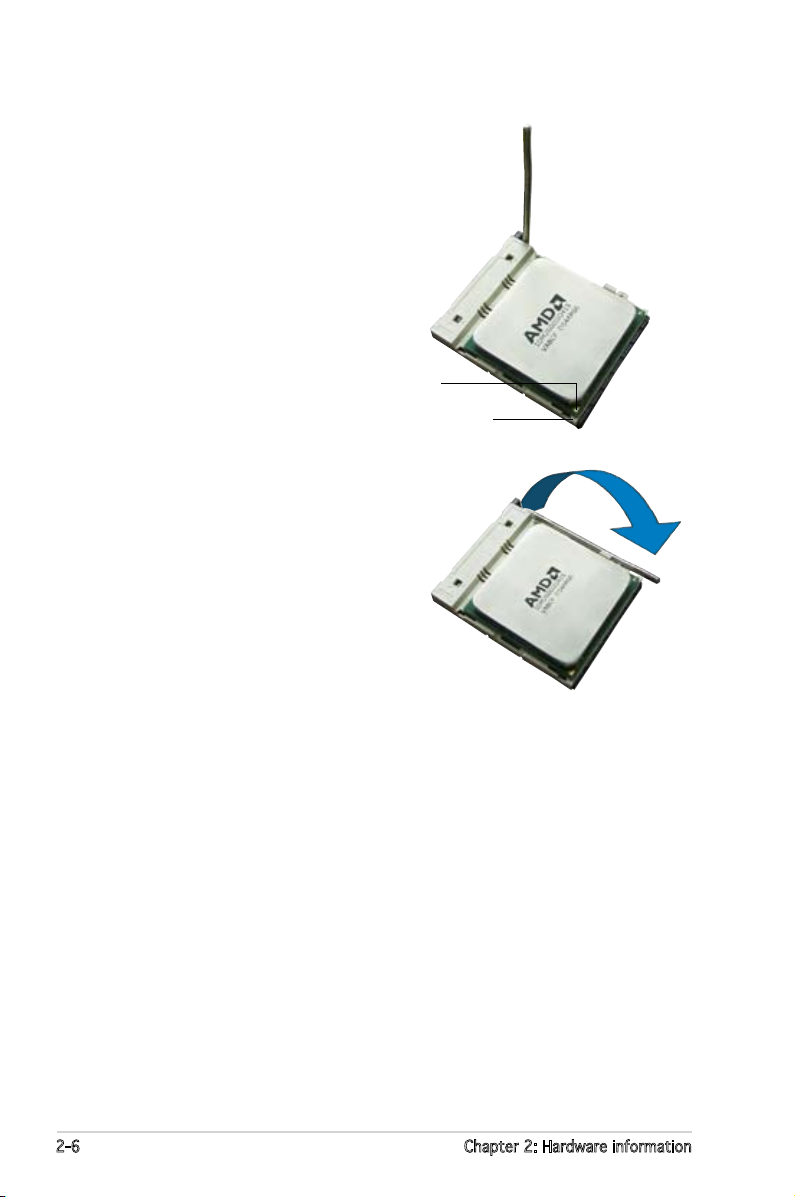
3. Position the CPU above the
socket such that the CPU corner
with the gold triangle matches
the socket corner with a small
triangle.
Gold triangle
5. When the CPU is in place, push
down the socket lever to secure
the CPU. The lever clicks on the
side tab to indicate that it is
locked.
6. Install a CPU heatsink and fan
following the instructions that
came with the heatsink package.
Small triangle
2-6 Chapter 2: Hardware information
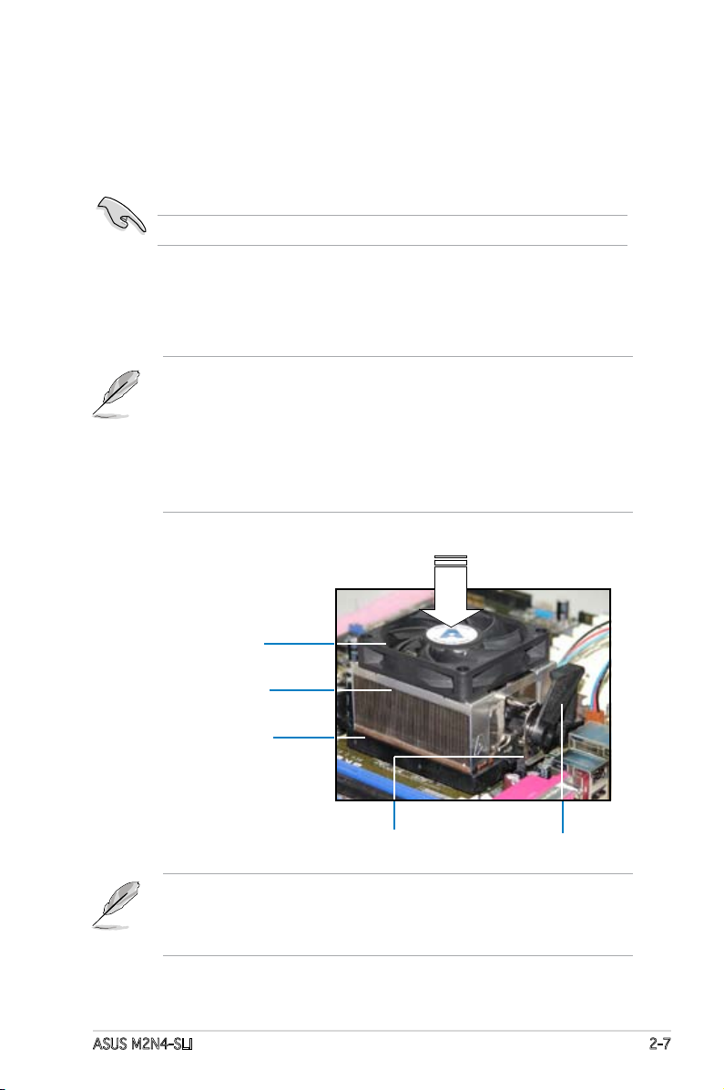
2.3.2 Installing the heatsink and fan
The the AMD Athlon™ FX, AMD Athlon 64™, AMD Sempron™ or AMD
Athlon™ X2 processor require a specially designed heatsink and fan
assembly to ensure optimum thermal condition and performance.
Make sure that you use only qualied heatsink and fan assembly.
Follow these steps to install the CPU heatsink and fan.
1. Place the heatsink on top of the installed CPU, making sure that the
heatsink ts properly on the retention module base.
• The retention module base is already installed on the motherboard
upon purchase.
• You do not have to remove the retention module base when
installing the CPU or installing other motherboard components.
• If you purchased a separate CPU heatsink and fan assembly, make
sure that a Thermal Interface Material is properly applied to the CPU
heatsink or CPU before you install the heatsink and fan assembly.
CPU Fan
CPU Heatsink
Retention Module Base
Retention bracket lockRetention bracket
Your boxed CPU heatsink and fan assembly should come with installation
instructions for the CPU, heatsink, and the retention mechanism. If the
instructions in this section do not match the CPU documentation, follow
the latter.
ASUS M2N4-SLI 2-7
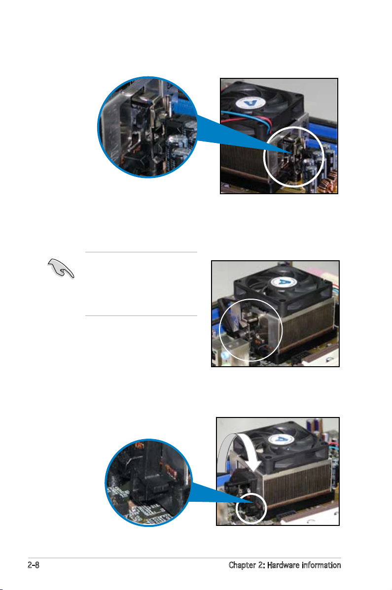
2. Attach one end of the retention bracket to the retention module base.
3. Align the other end of the retention bracket (near the retention
bracket lock) to the retention module base. A clicking sound denotes
that the retention bracket is in place.
Make sure that the fan and
heatsink assembly perfectly
ts the retention mechanism
module base, otherwise you
cannot snap the retention
bracket in place.
4. Push down the retention bracket lock on the retention mechanism to
secure the heatsink and fan to the module base.
2-8 Chapter 2: Hardware information

5. When the fan and heatsink assembly is in place, connect the CPU fan
R
M2N4-SLI
M2N4-SLI CPU Fan Connectors
GND
CPU FAN PWR
CPU FAN IN
CPU FAN PWM
CPU_FAN
cable to the connector on the motherboard labeled CPU_FAN.
Do not forget to connect the CPU fan connector! Hardware monitoring
errors can occur if you fail to plug this connector.
ASUS M2N4-SLI 2-9
2.4 System memory
R
M2N4-SLI
M2N4-SLI 240-pin DDR2 DIMM Sockets
DIMM_B1
DIMM_A2
DIMM_B2
DIMM_A1
112 Pins128 Pins
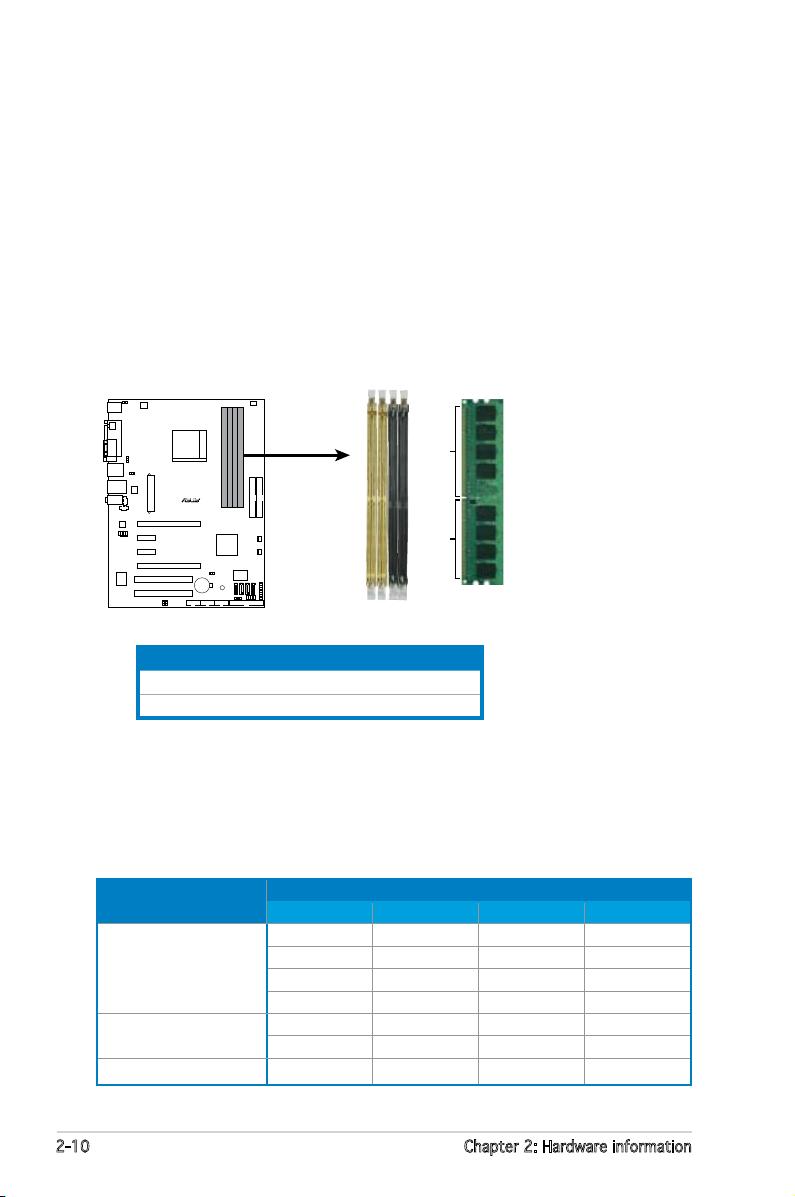
2.4.1 Overview
The motherboard comes with four Double Data Rate 2 (DDR2) Dual Inline
Memory Modules (DIMM) sockets.
A DDR2 module has the same physical dimensions as a DDR DIMM but has
a 240-pin footprint compared to the 184-pin DDR DIMM. DDR2 DIMMs are
notched differently to prevent installation on a DDR DIMM socket.
The gure illustrates the location of the DDR2 DIMM sockets:
Channel Sockets
Channel A DIMM_A1 and DIMM_A2
Channel B
DIMM_B1 and DIMM_B2
2.4.2 Memory congurations
You may install 256 MB, 512 MB, 1 GB, and 2GB unbuffered ECC/non-ECC
DDR2 DIMMs into the DIMM sockets.
Recommended Memory Congurations
Mode
Single Channel
Dual-channel (1)
Dual-channel (2)
DIMM_A1 DIMM_A2 DIMM_B1 DIMM_B2
Populated – – –
– Populated – –
– – Populated –
– – – Populated
Populated – Populated –
– Populated – Populated
Populated Populated Populated Populated
2-10 Chapter 2: Hardware information
Sockets
Loading…
- Инструкции и руководства
- Бренды
- ASUS
- M2N4-SLI
- Справочник Пользователя
Хорошее руководство по эксплуатации
Законодательство обязывает продавца передать покупателю, вместе с товаром, руководство по эксплуатации Asus M2N4-SLI. Отсутствие инструкции либо неправильная информация, переданная потребителю, составляют основание для рекламации в связи с несоответствием устройства с договором. В законодательстве допускается предоставлении руководства в другой, чем бумажная форме, что, в последнее время, часто используется, предоставляя графическую или электронную форму инструкции Asus M2N4-SLI или обучающее видео для пользователей. Условием остается четкая и понятная форма.
Что такое руководство?
Слово происходит от латинского «instructio», тоесть привести в порядок. Следовательно в инструкции Asus M2N4-SLI можно найти описание этапов поведения. Цель инструкции заключается в облегчении запуска, использования оборудования либо выполнения определенной деятельности. Инструкция является набором информации о предмете/услуге, подсказкой.
К сожалению немного пользователей находит время для чтения инструкций Asus M2N4-SLI, и хорошая инструкция позволяет не только узнать ряд дополнительных функций приобретенного устройства, но и позволяет избежать возникновения большинства поломок.
Из чего должно состоять идеальное руководство по эксплуатации?
Прежде всего в инструкции Asus M2N4-SLI должна находится:
— информация относительно технических данных устройства Asus M2N4-SLI
— название производителя и год производства оборудования Asus M2N4-SLI
— правила обслуживания, настройки и ухода за оборудованием Asus M2N4-SLI
— знаки безопасности и сертификаты, подтверждающие соответствие стандартам
Почему мы не читаем инструкций?
Как правило из-за нехватки времени и уверенности в отдельных функциональностях приобретенных устройств. К сожалению само подсоединение и запуск Asus M2N4-SLI это слишком мало. Инструкция заключает ряд отдельных указаний, касающихся функциональности, принципов безопасности, способов ухода (даже то, какие средства стоит использовать), возможных поломок Asus M2N4-SLI и способов решения проблем, возникающих во время использования. И наконец то, в инструкции можно найти адресные данные сайта Asus, в случае отсутствия эффективности предлагаемых решений. Сейчас очень большой популярностью пользуются инструкции в форме интересных анимаций или видео материалов, которое лучше, чем брошюра воспринимаются пользователем. Такой вид инструкции позволяет пользователю просмотреть весь фильм, не пропуская спецификацию и сложные технические описания Asus M2N4-SLI, как это часто бывает в случае бумажной версии.
Почему стоит читать инструкции?
Прежде всего здесь мы найдем ответы касательно конструкции, возможностей устройства Asus M2N4-SLI, использования отдельных аксессуаров и ряд информации, позволяющей вполне использовать все функции и упрощения.
После удачной покупки оборудования/устройства стоит посвятить несколько минут для ознакомления с каждой частью инструкции Asus M2N4-SLI. Сейчас их старательно готовят или переводят, чтобы они были не только понятными для пользователя, но и чтобы выполняли свою основную информационно-поддерживающую функцию.
Скачать файл PDF «ASUS M2N4-SLI Инструкция по эксплуатации» (4.11 Mb)
Популярность:
7924 просмотры
Подсчет страниц:
138 страницы
Тип файла:
Размер файла:
4.11 Mb
Google Ads: