

Version 1.1
Published November 2017
Copyright©2017 ASRock INC. All rights reserved.
Copyright Notice:
No part of this documentation may be reproduced, transcribed, transmitted, or
translated in any language, in any form or by any means, except duplication of
documentation by the purchaser for backup purpose, without written consent of
ASRock Inc.
Products and corporate names appearing in this documentation may or may not
be registered trademarks or copyrights of their respective companies, and are used
only for identication or explanation and to the owners’ benet, without intent to
infringe.
Disclaimer:
Specications and information contained in this documentation are furnished for
informational use only and subject to change without notice, and should not be
constructed as a commitment by ASRock. ASRock assumes no responsibility for
any errors or omissions that may appear in this documentation.
With respect to the contents of this documentation, ASRock does not provide
warranty of any kind, either expressed or implied, including but not limited to
the implied warranties or conditions of merchantability or tness for a particular
purpose.
In no event shall ASRock, its directors, ocers, employees, or agents be liable for
any indirect, special, incidental, or consequential damages (including damages for
loss of prots, loss of business, loss of data, interruption of business and the like),
even if ASRock has been advised of the possibility of such damages arising from any
defect or error in the documentation or product.
is device complies with Part 15 of the FCC Rules. Operation is subject to the following
two conditions:
(1) this device may not cause harmful interference, and
(2) this device must accept any interference received, including interference that
may cause undesired operation.
CALIFORNIA, USA ONLY
e Lithium battery adopted on this motherboard contains Perchlorate, a toxic substance
controlled in Perchlorate Best Management Practices (BMP) regulations passed by the
California Legislature. When you discard the Lithium battery in California, USA, please
follow the related regulations in advance.
“Perchlorate Material-special handling may apply, see ww w.dtsc.ca.gov/hazardouswaste/
perchlorate”
ASRock Website: http://www.asrock.com
AUSTRALIA ONLY
Our goods come with guarantees that cannot be excluded under the Australian
Consumer Law. You are entitled to a replacement or refund for a major failure and
compensation for any other reasonably foreseeable loss or damage caused by our
goods. You are also entitled to have the goods repaired or replaced if the goods fail
to be of acceptable quality and the failure does not amount to a major failure. If
you require assistance please call ASRock Tel : +886-2-28965588 ext.123 (Standard
International call charges apply)
e terms HDMI™ and HDMI High-Denition Multimedia Interface, and the HDMI
logo are trademarks or registered trademarks of HDMI Licensing LLC in the United
States and other countries.
Manufactured under license under U.S. Patent Nos: 5,956,674; 5,974,380; 6,487,535;
7,003,467 & other U.S. and worldwide patents issued & pending. DTS, the Symbol, &
DTS and the Symbol together is a registered trademark & DTS Connect, DTS Interactive,
DTS Neo:PC are trademarks of DTS, Inc. Product includes soware.
© DTS, Inc., All Rights Reserved.

Contents
Chapter 1 Introduction 1
1.1 Package Contents 1
1.2 Specications 2
1.3 Motherboard Layout 8
1.4 I/O Panel 10
Chapter 2 Installation 12
2.1 Installing the CPU 13
2.2 Installing the CPU Fan and Heatsink 16
2.3 Installing Memory Modules (DIMM) 17
2.4 Expansion Slots (PCI Express Slots) 19
2.5 Jumpers Setup 20
2.6 Onboard Headers and Connectors 21
2.7 SLITM and Quad SLITM Operation Guide 26
2.7.1 Installing Two SLITM-Ready Graphics Cards 26
2.7.2 Driver Installation and Setup 28
2.8 CrossFireXTM , 3-Way CrossFireXTM and Quad CrossFireXTM
Operation Guide 29
2.8.1 Installing Two CrossFireXTM-Ready Graphics Cards 29
2.8.2 Installing Three CrossFireXTM-Ready Graphics Cards 31
2.8.3 Driver Installation and Setup 32
2.9 M.2 WiFi/BT Module Installation Guide (M2_3) 33
2.10 M.2_SSD (NGFF) Module Installation Guide (M2_1 and M2_2) 35

Chapter 3 Software and Utilities Operation 39
3.1 Installing Drivers 39
3.2 A-Tuning 40
3.2.1 Installing A-Tuning 40
3.2.2 Using A-Tuning 40
3.3 ASRock Live Update & APP Shop 43
3.3.1 UI Overview 43
3.3.2 Apps 44
3.3.3 BIOS & Drivers 47
3.3.4 Setting 48
3.4 ASRock RGB LED 49
Chapter 4 UEFI SETUP UTILITY 51
4.1 Introduction 51
4.2 EZ Mode 52
4.3 Advanced Mode 53
4.3.1 UEFI Menu Bar 53
4.3.2 Navigation Keys 54
4.4 Main Screen 55
4.5 OC Tweaker Screen 56
4.6 Advanced Screen 67
4.6.1 CPU Conguration 68
4.6.2 Chipset Conguration 70
4.6.3 Storage Conguration 73
4.6.4 Intel® Thunderbolt 75

4.6.5 Super IO Conguration 76
4.6.6 ACPI Conguration 77
4.6.7 USB Conguration 79
4.6.8 Trusted Computing 80
4.7 Tools 81
4.8 Hardware Health Event Monitoring Screen 84
4.9 Security Screen 87
4.10 Boot Screen 88
4.11 Exit Screen 91

Z370 Extreme4
Chapter 1 Introduction
ank you for purchasing ASRock Z370 Extreme4 motherboard, a reliable
motherboard produced under ASRock’s consistently stringent quality control.
It delivers excellent performance with robust design conforming to ASRock’s
commitment to quality and endurance.
In this documentation, Chapter 1 and 2 contains the introduction of the
motherboard and step-by-step installation guides. Chapter 3 contains the operation
guide of the soware and utilities. Chapter 4 contains the conguration guide of
the BIOS setup.
Becau se the motherboard specications and the BIOS soware might be updated, the
content of this documentation will be subject to change without notice. In case any modications of this documentation occur, the updated version will be available on ASRock’s
website w ithout further notice. If you require technical support related to this motherboard, please visit our website for specic information about the model you are using. You
may nd the l atest VGA cards and CPU suppor t list on ASRock’s website a s well. ASRock
website http://www.asrock.com.
1.1 Package Contents
ASRock Z370 Extreme4 Motherboard (ATX Form Factor)
•
ASRock Z370 Extreme4 Quick Installation Guide
•
ASRock Z370 Extreme4 Support CD
•
1 x I/O Panel Shield
•
4 x Serial ATA (SATA) Data Cables (Optional)
•
1 x ASRock SLI_HB_Bridge_2S Card (Optional)
•
3 x Screws for M.2 Socket (Optional)
•
English
1

1.2 Specications
Platform
CPU
Chipset
Memory
•
•
•
•
•
•
•
•
•
•
•
* Please refer to Memory Support List on ASRock’s website for
more information. (http://www.asrock.com/)
* 8th Gen Intel® CPU supports DDR4 up to 2666.
•
•
•
•
ATX Form Factor
Supports 8th Generation Intel® CoreTM Processors (Socket
1151)
Digi Power design
12 Power Phase design
Supports Intel® Turbo Boost 2.0 Technology
Supports Intel® K-Series unlocked CPUs
Supports ASRock BCLK Full-range Overclocking
Intel® Z370
Dual Channel DDR4 Memory Technology
4 x DDR4 DIMM Slots
Supports DDR4 4333+(OC)*/4000(OC)/3866(OC)/
3800(OC)/3733(OC)/3600(OC)/3200(OC)/2933(OC)/2800
(OC)/2666/2400/2133 non-ECC, un-buered memory
Supports ECC UDIMM memory modules (operate in non-
ECC mode)
Max. capacity of system memory: 64GB
Supports Intel® Extreme Memory Prole (XMP) 2.0
15μ Gold Contact in DIMM Slots
English
2
Expansion
Slot
3 x PCI Express 3.0 x16 Slots (PCIE2/PCIE4/PCIE6: single
•
at x16 (PCIE2); dual at x8 (PCIE2) / x8 (PCIE4); triple at x8
(PCIE2) / x8 (PCIE4) / x4 (PCIE6))*
* Supports NVMe SSD as boot disks
3 x PCI Express 3.0 x1 Slots (Flexible PCIe)
•
Supports AMD Quad CrossFireXTM, 3-Way CrossFireXTM
•
and CrossFireXTM
Supports NVIDIA® Quad SLITM and SLI
•
1 x M.2 Socket (Key E), supports ty pe 2230 WiFi/BT module
•
15μ Gold Contact in VGA PCIe Slot (PCIE2)
•
TM

Graphics
Z370 Extreme4
Intel® UHD Graphics Built-in Visuals and the VGA outputs
•
can be supported only with processors which are GPU
integrated.
Supports Intel® UHD Graphics Built-in Visuals : Intel®
•
Quick Sync Video with AVC, MVC (S3D) and MPEG-2 Full
HW Encode1, Intel® InTruTM 3D, Intel® Clear Video HD
Technology, Intel® InsiderTM, Intel® UHD Graphics
DirectX 12
•
HWAEncode/Decode: VP9 8-bit, VP9 10-bit (Encode only),
•
VP8, HEVC (MPEG-H Part2, h.265), AVC (MPEG4, h.264),
MPEG2-Part2 (h.262), JPEG/MJPEG,VC-1
Max. shared memory 1024MB
•
* e size of ma ximum shared memory may vary from dierent
operating systems.
ree graphics output options: D-Sub, DVI-D and HDMI
•
Supports Triple Monitor
•
Supports HDMI with max. resolution up to 4K x 2K
•
(4096×2160) @ 30Hz
Supports DVI-D with ma x. resolution up to 1920×1200 @
•
60Hz
Supports D-Sub with max. resolution up to 1920×1200 @
•
60Hz
Supports Auto Lip Sync, Deep Color (12bpc), xvYCC and
•
HBR (High Bit Rate Audio) with HDMI Port (Compliant
HDMI monitor is required)
Supports HDCP with DVI-D and HDMI Ports
•
Supports 4K Ultra HD (UHD) playback with HDMI Port
•
Audio
7.1 CH HD Audio with Content Protection (Realtek
•
ALC1220 Audio Codec)
Premium Blu-ray Audio support
•
Supports Surge Protection
•
Supports Purity SoundTM 4
•
— Nichicon Fine Gold Series Audio Caps
— 120dB SNR DAC with Dierential Amplier
— NE5532 Premium Headset Amplier for Front Panel
Audio Connector (Supports up to 600 Ohm headsets)
— Pure Power-In
English
3

LAN
Rear Panel
I/O
— Direct Drive Technology
— PCB Isolate Shielding
— Impedance Sensing on Front Out port
—
Individual PCB Layers for R/L Audio Channel
— RGB LED
— 15μ Gold Audio Connector
Supports DTS Connect
•
Gigabit LAN 10/100/10 00 Mb/s
•
Giga PHY Intel® I219V
•
Supports Wake-On-LAN
•
Supports Lightning/ESD Protection
•
Supports Energy Ecient Ethernet 802.3az
•
Supports PXE
•
2 x Antenna Ports
•
1 x PS/2 Mouse/Keyboard Port
•
1 x D-Sub Port
•
1 x DVI-D Port
•
1 x HDMI Port
•
1 x Optical SPDIF Out Port
•
1 x USB 3.1 Gen2 Type-A Port (10 Gb/s) (ASMedia ASM3142)
•
(Supports ESD Protection)
1 x USB 3.1 Gen2 Type-C Port (10 Gb/s) (ASMedia ASM3142)
•
(Supports ESD Protection)
4 x USB 3.1 Gen1 Ports (Intel® Z370) (Supports ESD
•
Protection)
1 x RJ-45 LAN Port with LED (ACT/LINK LED and SPEED
•
LED)
HD Audio Jacks: Rear Speaker / Centra l / Bass / Line in /
•
Front Speaker / Microphone
English
4
Storage
6 x SATA3 6.0 Gb/s Connectors, support RAID (RAID 0,
•
RAID 1, RAID 5, RAID 10, Intel Rapid Storage Technology
15), NCQ, AHCI and Hot Plug*
2 x SATA3 6.0 Gb/s Connectors by ASMedia ASM1061, sup-
•
port NCQ, AHCI and Hot Plug
* M2_1, SATA3_0 and SATA3_1 share lanes. If either one of
them is in use, the others will be disabled.
* M2_ 2, SATA3_4 and SATA3_5 share lanes. If either one of
them is in use, the others will be disabled.

Connector
Z370 Extreme4
1 x Ultra M.2 Socket (M2_1), supports M Key type
•
2230/2242/2260/2280 M.2 SATA3 6.0 Gb/s module and M.2
PCI Express module up to Gen3 x4 (32 Gb/s)**
1 x Ultra M.2 Socket (M2_2), supports M Key ty pe
•
2230/2242/2260/2280/22110 M.2 SATA3 6.0 Gb/s module
and M.2 PCI Express module up to Gen3 x4 (32 Gb/s)**
** Supports Intel® OptaneTM Tech nolo gy
** Supports NVMe SSD as boot disks
** Supports ASRock U.2 Kit
1 x COM Port Header
•
1 x TPM Header
•
1 x Power LED and Speaker Header
•
1 x RGB LED Header
•
* Supports in total up to 12V/3A, 36W LED Strip
1 x CPU Fan Connector (4-pin)
•
* e CPU Fan Connector supports the CPU fan of ma ximum
1A (12W) fan power.
1 x CPU Optional/Water Pump Fan Connector (4-pin)
•
* e CPU Optional/Water Pump Fan supports the water cooler
fan of maximum 1.5A (18W) fan power.
2 x Chassis Fan Connectors (4-pin) (Smart Fan Speed
•
Control)
1 x Chassis Optional/Water Pump Fan Connector (4-pin)
•
* e Chassis Optiona l/Water Pump Fan supports the water
cooler fan of maximum 1.5A (18W) fan power.
* CHA_FAN1 and CHA _FAN2 can auto detect if 3-pin or 4-pin
fan is in use.
1 x 24 pin ATX Power Connector (Hi-Density Power
•
Connec tor)
1 x 8 pin 12V Power Connector (Hi-Density Power
•
Connec tor)
1 x Front Panel Audio Connector (15μ Gold Audio
•
Connec tor)
1 x underbolt AIC Connector (5-pin)
•
3 x USB 2.0 Headers (Support 6 USB 2.0 ports) (Intel® Z370)
•
(Supports ESD Protection)
1 x USB 3.1 Gen1 Header (Supports 2 USB 3.1 Gen1 ports)
•
(Intel® Z370) (Supports ESD Protection)
English
5

BIOS
Feature
Hardware
Monitor
1 x USB 3.1 Gen1 Header (Supports 2 USB 3.1 Gen1 ports)
•
(ASMedia ASM1074 hub) (Supports ESD Protection)
1 x Front Panel Type C USB 3.1 Gen1 Header (ASMedia
•
ASM1074 hub)
2 x AMI UEFI Legal BIOS with multilingual GUI support
•
(1 x Main BIOS and 1 x Backup BIOS)
Supports Secure Backup UEFI Technology
•
ACPI 6.0 Compliant wake up events
•
SMBIOS 2.7 Support
•
CPU Core/Cache, GT Core/Cache, DRAM, PCH 1.0V,
•
VCCIO, VCCST, VCCSA, VCCPLL, CPU Internal PLL, GT
PLL, Ring PLL, System Agent PLL, Memory Controller PLL
Voltage Multi-adjustment
Temperature Sensing: CPU, CPU Optional/Water Pump,
•
Chassis, Chassis Optional/Water Pump Fans
Fan Tachometer: CPU, CPU Optional/Water Pump, Chassis,
•
Chassis Optional/Water Pump Fans
Quiet Fan (Auto adjust chassis fan speed by CPU tempera-
•
ture): CPU, CPU Optional/Water Pump, Chassis, Chassis
Optional/Water Pump Fans
Fan Multi-Speed Control: CPU, CPU Optional/Water Pump,
•
Chassis, Chassis Optional/Water Pump Fans
Voltage monitoring: +12V, +5V, +3.3V, CPU Vcore, DRAM,
•
VPPM, PCH 1.0V, VCCSA, VCCST
English
6
Microso® Windows® 10 64-bit
OS
Certications
* For detailed product information, please visit our website: http://www.asrock .com
•
FCC, CE
•
ErP/EuP ready (ErP/EuP ready power supply is required)
•

Z370 Extreme4
Please realiz e that the re is a certain r isk involved with o verclocking, including adjusting
the setting in the BIOS, applying Untied Overclocking Technolog y, or using third-party
overclocking to ols. O verclocking may aect your system’s stability, or even c ause damage to
the components and devices of your system. It should be don e at your ow n risk and expense.
We are not responsibl e for possible damage caused by overclo cking.
English
7
Intel
Z370
DDR 4_A2 (6 4 bit, 28 8-pin mo dule)
DDR 4_A1 (6 4 bit, 28 8-pin mo dule)
DDR 4_B2 (6 4 bit, 28 8-pin mo dule)
DDR 4_B1 (6 4 bit, 28 8-pin mo dule)
ATX12V1
ATXP WR 1
LAN
PCIE2
Top:
RJ-45
USB 3.1 Gen1
T: USB3
B: USB4
Top:
Central/Bass
Center :
REAR SPK
Top:
LINE IN
Center :
FRONT
Bottom :
Optica l
SPDIF
Bottom :
MIC IN
PCIE4
HDLED RESET
PLED PWRBTN
PANEL1
1
1
SPK_PLED1
COM1
1
1
HD_AUDIO1
PCIE6
SATA3_2_3
SATA3_0_1
SATA3_A1_ A2
PCIE1
RoHS
6
8
9
10
11
12
13
USB_1_2
1
19
USB_3_4
1
20
USB_5_6
1
18 1726
27
HDMI1
SATA3_4_5
1
5
4
25
14
BIOS_A1
BIOS_B1
BIOS_B_LED1
BIOS
BIOS
BIOS_A_LED1
USB 3.1 Ge n1
T: USB1
B: USB2
PS2
Keybo ard
/Mous e
CMOS
Battery
PCIE3
M2_1
M2_2
CT2
CT2
CT3
CT3
CT4
CT4CT5
T B1
1
23
2
USB3_7 _8
1
1516
CPU_FAN1
7
21
1
TPMS1
PCIE5
USB 3.1 Gen2
T: USB31_TA_1
B: USB31_TC_1
CT1
CT1
CHA_FAN1
Ultra M.2
PCIe Gen3x4
CHA_FAN2
CPU_OPT/
W_PUMP
CHA_FAN3/W_PUMP
3
USB3_5 _6
1
RGB_LED
1
24
CLRMOS1
1
22
Ult ra M.2
PCIe G en3 x4
USB3_TC_1
Purity
Sound 4
TM
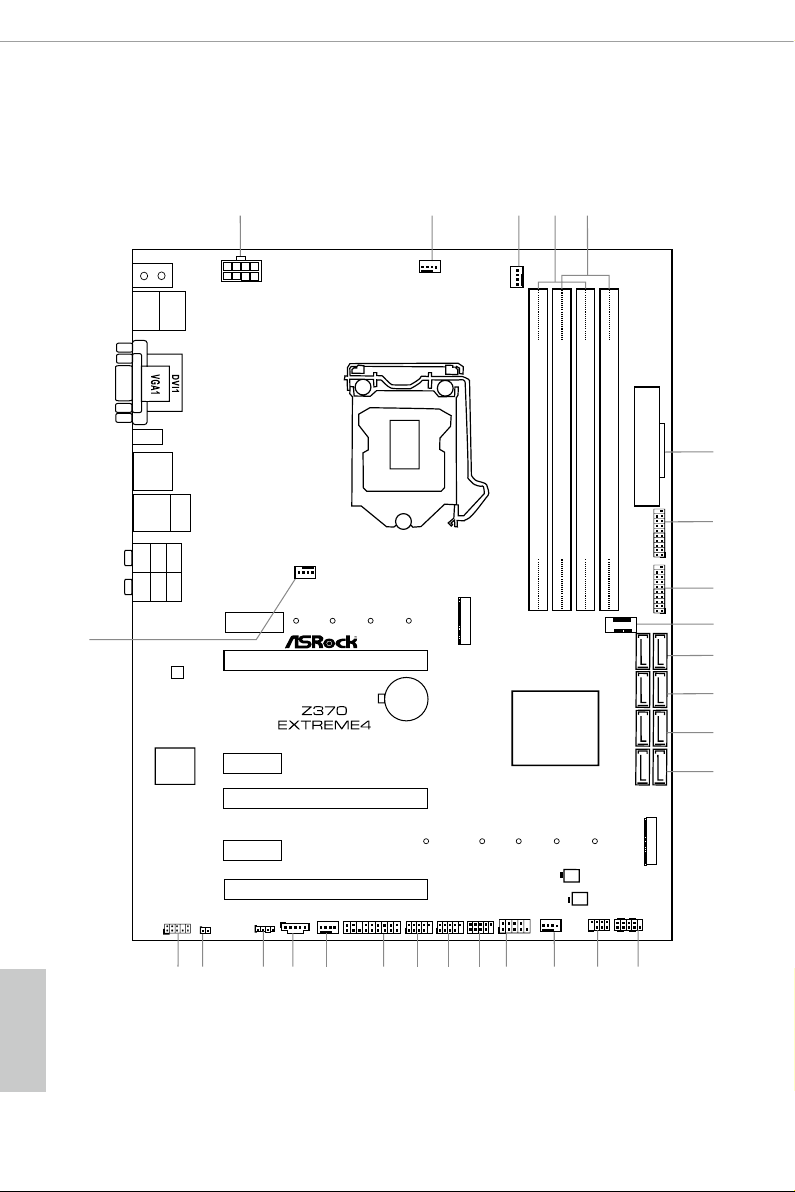
1.3 Motherboard Layout
English
8

No. Description
1 ATX 12V Power Connector (ATX12V1)
2 CPU Fan Connector (CPU_FAN1)
3 CPU Fan / Waterpump Fan Connector (CPU_OPT/W_PUMP)
4 2 x 288-pin DDR4 DIMM Slots (DDR4_A1, DDR4_B1)
5 2 x 288-pin DDR4 DIMM Slots (DDR4_A2, DDR4_B2)
6 ATX Power Connector (ATXPWR1)
7 USB 3.1 Gen1 Header (USB3_5_6)
8 USB 3.1 Gen1 Header (USB3_7_8)
9 Front Panel Type C USB 3.1 Gen1 Header (USB3_TC_1)
10 SATA3 Connectors (SATA3_4_5)
11 SATA3 Connectors (SATA3_2_3)
12 SATA3 Connectors (SATA3_0_1)
13 SATA3 Connectors (SATA3_A1_A2)
14 System Panel Header (PANEL1)
15 Power LED and Speaker Header (SPK_PLED1)
16 Chassis Fan / Waterpump Fan Connector (CHA_FAN3/W_PUMP)
17 COM Port Header (COM1)
18 USB 2.0 Header (USB_ 5_6)
19 USB 2.0 Header (USB_1_2)
20 USB 2.0 Header (USB_3_4)
21 TPM Header (TPMS1)
22 Chassis Fan Connector (CHA_FAN2)
23 underbolt AIC Connector (TB1)
24 RGB LED Header (RGB_LED)
25 Clear CMOS Jumper (CLRMOS1)
26 Front Panel Audio Header (HD_AUDIO1)
27 Chassis Fan Connector (CHA_FAN1)
Z370 Extreme4
English
9

1.4 I/O Panel
6
1
2 547
3
15 10131416
12
No. Description No. Description
1 PS/2 Mouse/Keyboard Port (PS2_KB1) 9 Optical SPDIF Out Port
2 D-Sub Port 10 USB 3.1 Gen1 Ports (USB3_34)
3 LAN RJ-45 Port* 11 USB 3.1 Gen2 Type-A Port (USB31_TA_1)
4 Central / Bass (Orange) 12 USB 3.1 Gen2 Type-C Port (USB31_TC_1)
5 Rear Speaker (Black) 13 HDMI Port
6 Line In (Light Blue) 14 DVI-D Port
7 Front Speaker (Lime)** 15 USB 3.1 Gen1 Port (USB3_12)
8 Microphone (Pink) 16 Antenna Ports
8911
English
10
Z370 Extreme4
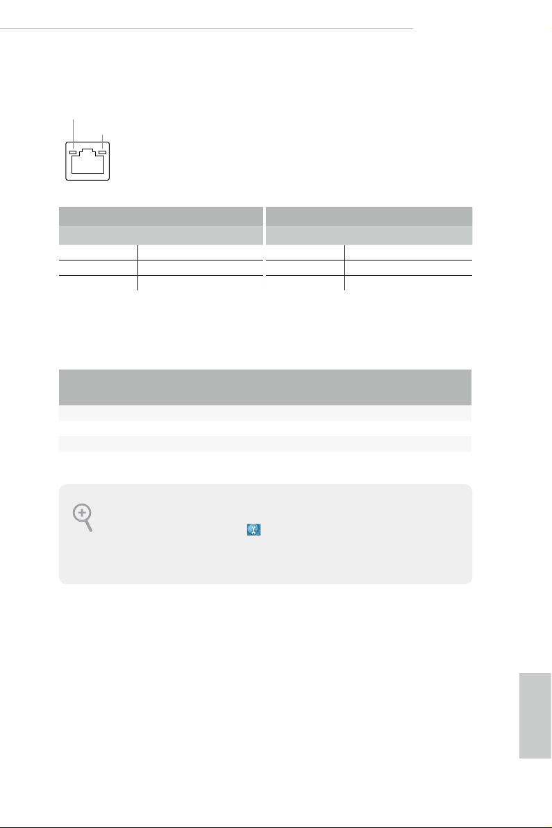
* ere are two LEDs on each LAN port. Please refer to the table below for the LAN port LED indications.
ACT/LINK LED
SPEED LED
LAN Por t
Activity / Link LED Speed LED
Status Description Status Description
O No Link O 10Mbps connection
Blinking Data Activity Orange 100Mbps connection
On Link Green 1Gbps connection
** If you use a 2- channel speaker, plea se connect the speake r’s plug into “Front Speaker Jack”. See the table below
for connection d etails in accordance w ith the type of speaker you use.
Audio Output
Channels
Front Speaker
(No. 7)
Rear Speaker
(No. 5)
Central / Bass
(No. 4)
2 V — — —
4 V V — —
6 V V V —
8 V V V V
To enable Multi-Streaming, you need to connect a front panel audio cable to the front
panel au dio header. Aer re starting your computer, you will nd the “Mixe r” tool on your
system. Plea se sele ct “Mixe r ToolBox” , click “Enable playback multi-streaming”, and
click “ok”. Choose “2CH”, “4CH”, “6CH”, or “8CH” and then you are a llowed to select
“Realtek HDA Primary output” to u se the Rear Speaker, Central/Ba ss, and Front Speaker,
or select “Realtek HDA Audio 2nd output” to use the front panel audio.
Line In
(No. 6)
English
11

Chapter 2 Installation
is is an ATX form factor motherboard. Before you install the motherboard, study
the conguration of your chassis to ensure that the motherboard ts into it.
Pre-installation Precautions
Take note of the following precautions before you install motherboard components
or change any motherboard settings.
Make sure to unplug the power cord before installing or removing the motherboard
•
components. Failure to do so may cause physical injuries and damages to motherboard
components.
In order to avoid damage from static electricity to the motherboard’s components,
•
NEVER place your motherboard directly on a carpet. Also remember to use a grounded
wrist strap or touch a safety grounded object before you handle the components.
Hold components by the edges and do not touch the ICs.
•
Whenever you uninstall any components, place them on a grounded anti-static pad or
•
in the bag that comes with the components.
When placing screws to secure the motherboard to the chassis, please do not over-
•
tighten the screws! Doing so may damage the motherboard.
English
12
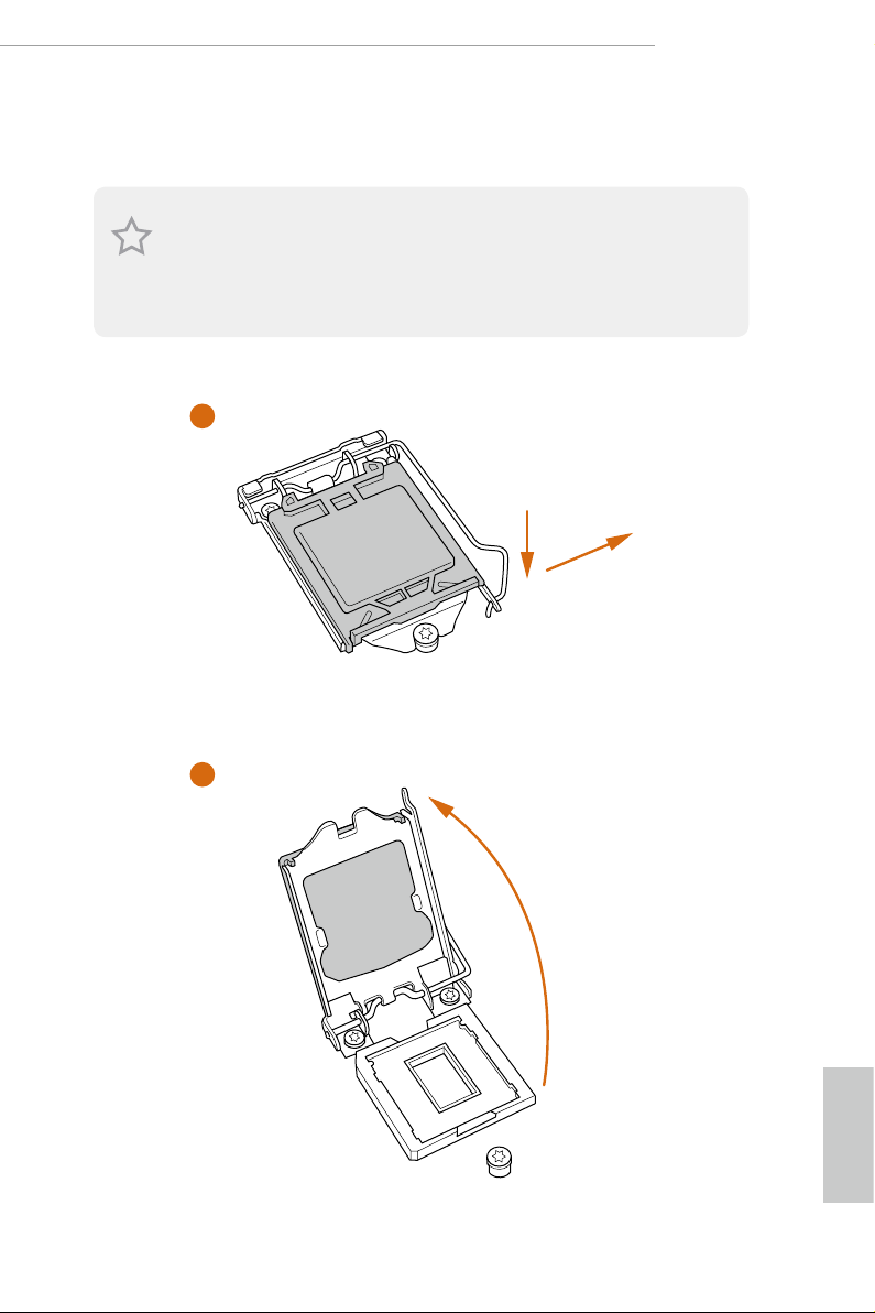
2.1 Installing the CPU
1. Before you insert the 1151-Pin CPU into the socket, please check if the P nP cap is on the
socket, if the CPU surface is unclean, or if there are any bent pins in the sock et. Do not
force to in sert the CPU into the socket if above situation is found . Otherwise, the CPU
will be seriously damaged.
2. Unplug all power c ables before in stalling the CPU.
1
Z370 Extreme4
A
B
2
English
13
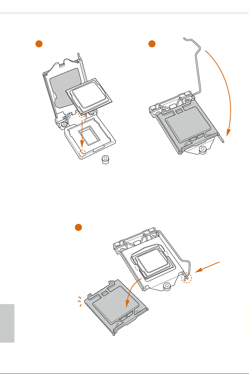
3
4
English
14
5

Please save and replace the cover if the processor i s removed. e cover must be placed if
you wish to return the motherboard for aer service.
Z370 Extreme4
15
English
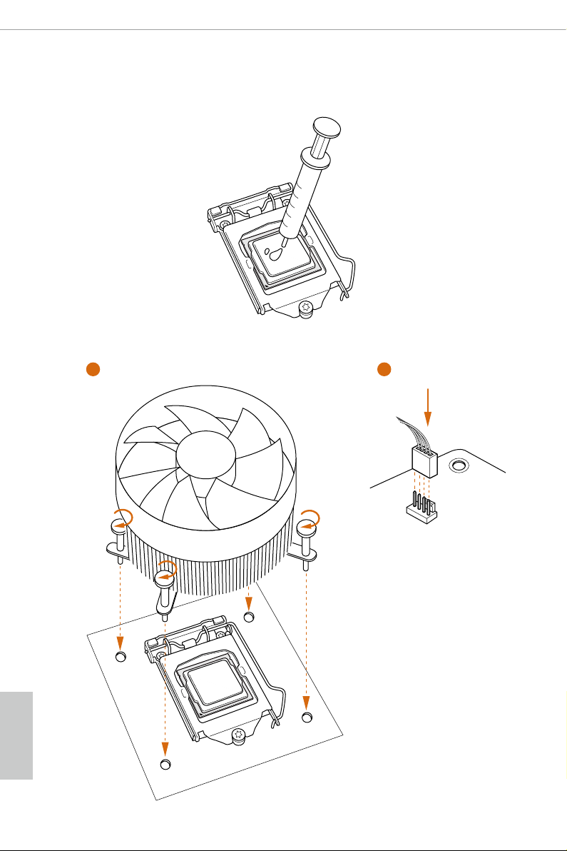
2.2 Installing the CPU Fan and Heatsink
1 2
English
16
FAN
CPU_
Z370 Extreme4
2.3 Installing Memory Modules (DIMM)
is motherboard provides four 288-pin DDR4 (Double Data Rate 4) DIMM slots,
and supports Dual Channel Memory Technology.
1. For dual channel cong uration , you always need to in stall identical (the same b rand,
speed , size and chip-type) DDR4 DIMM pairs.
2. It is unable to activate Dual Channel Memor y Technology with only one or three memory
module installed.
3. It is not allowed to install a DDR, DDR2 or DDR3 memory module into a DDR4 sl ot;
otherwise , this motherboard and DIM M may be damaged.
Dual Channel Memory Conguration
Priority DDR4_A1 DDR4_A2 DDR4_B1 DDR4_B2
1 Populated Populated
2 Populated Populated Populated Populated
e DIMM only ts in one correct orie ntation. It will cause permanent dam age to the
motherboard and the DIMM if you force the DIMM into the slot at incorrect orientation.
17
English

1
2
English
18
3
2.4 Expansion Slots (PCI Express Slots)
ere are 6 PCI Express slots on the motherboard.
Before installing an ex pansion card, please make sure that the power supply is switched o
or the power cord is unplug ged. Pl ease re ad the documentation of the expansion card and
make necessary hardware settings for the card before you start the installation.
PCIe slots:
PCIE1 (PCIe 3.0 x1 slot) is used for PCI Express x1 lane width cards.
PCIE2 (PCIe 3.0 x16 slot) is used for PCI Express x16 lane width graphics cards.
PCIE3 (PCIe 3.0 x1 slot) is used for PCI Express x1 lane width cards.
PCIE4 (PCIe 3.0 x16 slot) is used for PCI Express x8 lane width graphics cards.
PCIE5 (PCIe 3.0 x1 slot) is used for PCI Express x1 lane width cards.
PCIE6 (PCIe 3.0 x16 slot) is used for PCI Express x4 lane width graphics cards.
PCIe Slot Congurations
PCIE2 PCIE4 PCIE6
Z370 Extreme4
Single Graphics Card x16 N/A N/A
Two Graphics Cards in
CrossFireXTM or SLITM
Mode
ree Graphics Cards in
3-Way CrossFireXTM Mode
For a better ther mal environme nt, ple ase connect a ch assis fan to the motherboard’s ch assis fan connector (CHA_ FAN1, CHA_FAN2 or CHA_ FAN3 ) when using multiple graphic s
cards.
x8 x8 N/A
x8 x8 x4
English
19
2.5 Jumpers Setup
e illustration shows how jumpers are setup. When the jumper cap is placed on
the pins, the jumper is “Short”. If no jumper cap is placed on the pins, the jumper is
“O pen”.
English
Clear CMOS Jumper
(CLRCMO S1)
(see p.8, No. 25)
CLRCMOS1 allows you to clear the data in CMOS. e data in CMOS includes
system setup information such as system password, date, time, and system setup
parameters. To clear and reset the system parameters to default setup, please
turn o the computer and unplug the power cord, then use a jumper cap to short
the pins on CLRCMOS1 for 3 seconds. Please remember to remove the jumper
cap aer clearing the CMOS. If you need to clear the CMOS when you just nish
updating the BIOS, you must boot up the system rst, and then shut it down
before you do the clear-CMOS action.
2-pin Jumper
Short: Clear CMOS
Open: Default
20
2.6 Onboard Headers and Connectors
Onboard headers and connectors are NOT jump ers. Do NOT place jumper caps over these
heade rs and connectors. Placing jumper caps over the headers and connectors will cause
permanent damage to the motherboard.
Z370 Extreme4
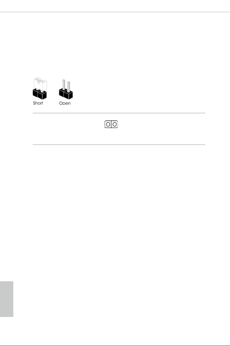
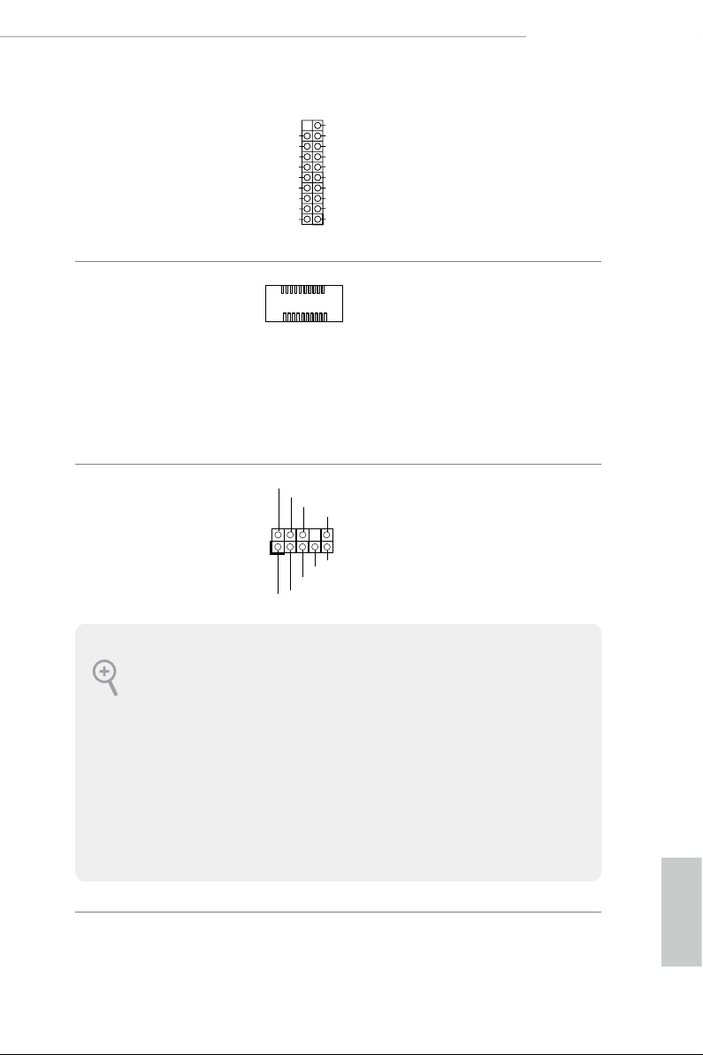
System Panel Header
(9-pi n PANEL1)
(see p.8, No. 14)
PWRBTN (Power Button):
Connec t to the power button on the ch assi s front panel. You may congure the way to tur n
o your system using the power button.
RESET (Reset B utton):
Connec t to the reset button on the ch assi s front panel. P ress the reset button to re start the
computer if the computer f reezes and fails to per form a normal restar t.
PLED (Syste m Power LED):
Connec t to the power status indicator on the chas sis front panel. e LED i s on when the
system is operating. e LED keeps blinking when the system is in S1/S3 sleep state. e
LED is o when the system is in S4 slee p state or powered o (S5).
HDLED (Ha rd Drive Activity LED):
Connec t to the hard drive ac tivity LED on the chassis front panel. e LED is on when the
hard drive is reading or wr iting data.
e front panel de sign may dier by chassis. A front panel module mainly consists of powe r
button, reset button , power LED, hard dr ive activity LED, speaker and etc. When connecting your ch assi s front panel module to thi s header, make sure the wire a ssignments and the
pin assignments are matched correctly.
PLED+
PLED-
HDLED-
HDLED+
PWRBTN#
GND
RESET#
GND
GND
Connect the power
button, reset button and
system status indicator on
the chassis to this header
according to the pin
assignments below. Note
the positive and negative
pins before connecting
the cables.
English
21
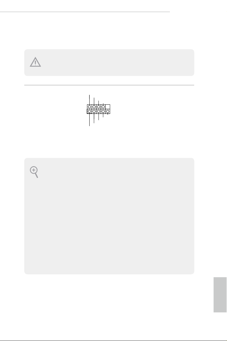
Power LED and Speaker
1
+5V
DUMMY
PLED+
PLED+
PLED-
DUMMY
SPEAKER
DUMMY
GND
GND
P+
P-
USB_PWR
P+
P-
USB_PWR
1
Header
(7-pin SPK_PLED1)
(see p.8, No. 15)
Please connect the
chassis power LED and
the chassis speaker to this
header.
English
Serial ATA3 Connectors
(SATA3_4_5:
see p.8, No. 10)
(SATA3_2_3:
see p.8, No. 11)
(SATA3_0_1:
see p.8, No. 12)
(SATA3_A1_A2:
see p.8, No. 13)
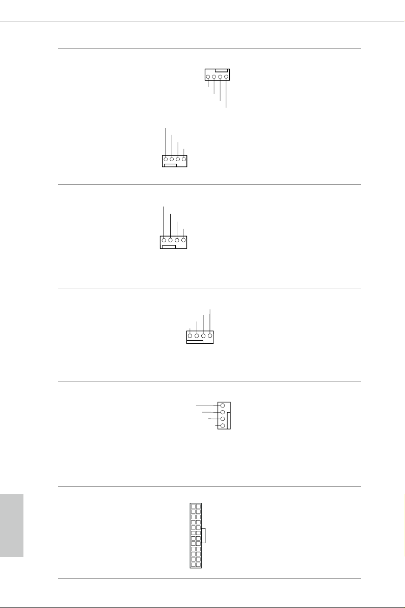
USB 2.0 Headers
(9-pin USB_1_2)
(see p.8, No. 19)
(9-pin USB_3_4)
(see p.8, No. 20)
(9-pin USB_5_6)
(see p.8, No. 18)
SATA3_2SATA3_0
SATA3_A1 SATA3_4
ese eight SATA3
connectors support SATA
data cables for internal
storage devices with up to
6.0 Gb/s data transfer rate.
* M2_1, SATA3_0 and
SATA3_3SATA3_1
SATA3_1 share lanes. If
either one of them is in
use, the others will be
disabled.
* M2_ 2, SATA3_4 and
SATA3_5 share lanes. If
either one of them is in
use, the others will be
SATA3_A2 SATA3_5
disabled.
*To minimize the boot
time, use Intel® Z370
SATA ports (SATA3_0)
for your bootable devices.
ere are three headers
on this motherboard.
Each USB 2.0 header can
support two ports.
22
Z370 Extreme4
J_SENSE
OUT2_L
1
MIC_RET
PRESENCE#
GND
OUT2_R
MIC2_R
MIC2_L
OUT_RET
USB 3.1 Gen1 Headers
(19-pin USB3_5_6)
(see p.8, No. 7)
(19-pin USB3_7_8)
(see p.8, No. 
Front Panel Type C USB
3.1 Gen1 Header
(26-pin USB3_TC_1)
(see p.8, No. 9)
Front Panel Audio Header
(9-pin HD_ AUDIO1)
(see p.8, No. 26)
Vbus
IntA_PA_SSRX-
IntA_PA_SSRX+
GND
IntA_PA_SSTX-
IntA_PA_SSTX+
GND
IntA_PA_D-
IntA_PA_D+
VbusVbus
IntA_PB_SSRX-
IntA_PB_SSRX+
GND
IntA_PB_SSTX-
IntA_PB_SSTX+
GND
IntA_PB_D-
IntA_PB_D+
Dummy
ere are two headers on
this motherboard. Each
USB 3.1 Gen1 header can
support two ports.
ere is one Front
Panel Type C USB 3.1
Gen1 Header on this
motherboard. is header
is used for connecting a
USB 3.1 Gen1 module for
additional USB 3.1 Gen1
ports.
is header is for
connecting audio devices
to the front audio panel.
1. High Denition Audio support s Jack Sensing, but the panel wire on the cha ssis must sup port HDA to function correctly. Ple ase fol low the instructions in our manual and chassis
manual to install your system.
2. If you use an AC’97 audio panel , please install it to th e front panel audio header by the
steps below:
A. Connect Mic_IN (MIC) to MIC2_ L.
B. Conne ct Audio_R (RIN) to OUT2_R and Audio_ L (LIN) to OUT2_ L.
C. Connect Ground (GND) to Ground (GND).
D. MIC_ RET and OUT_RET are for the HD audio panel only. You don’t ne ed to conn ect
them for the AC’97 audio panel .
E. To activate the front mic, go to the “FrontMic” Tab in the Realtek Control panel and
adjust “Recording Volume”.
English
23
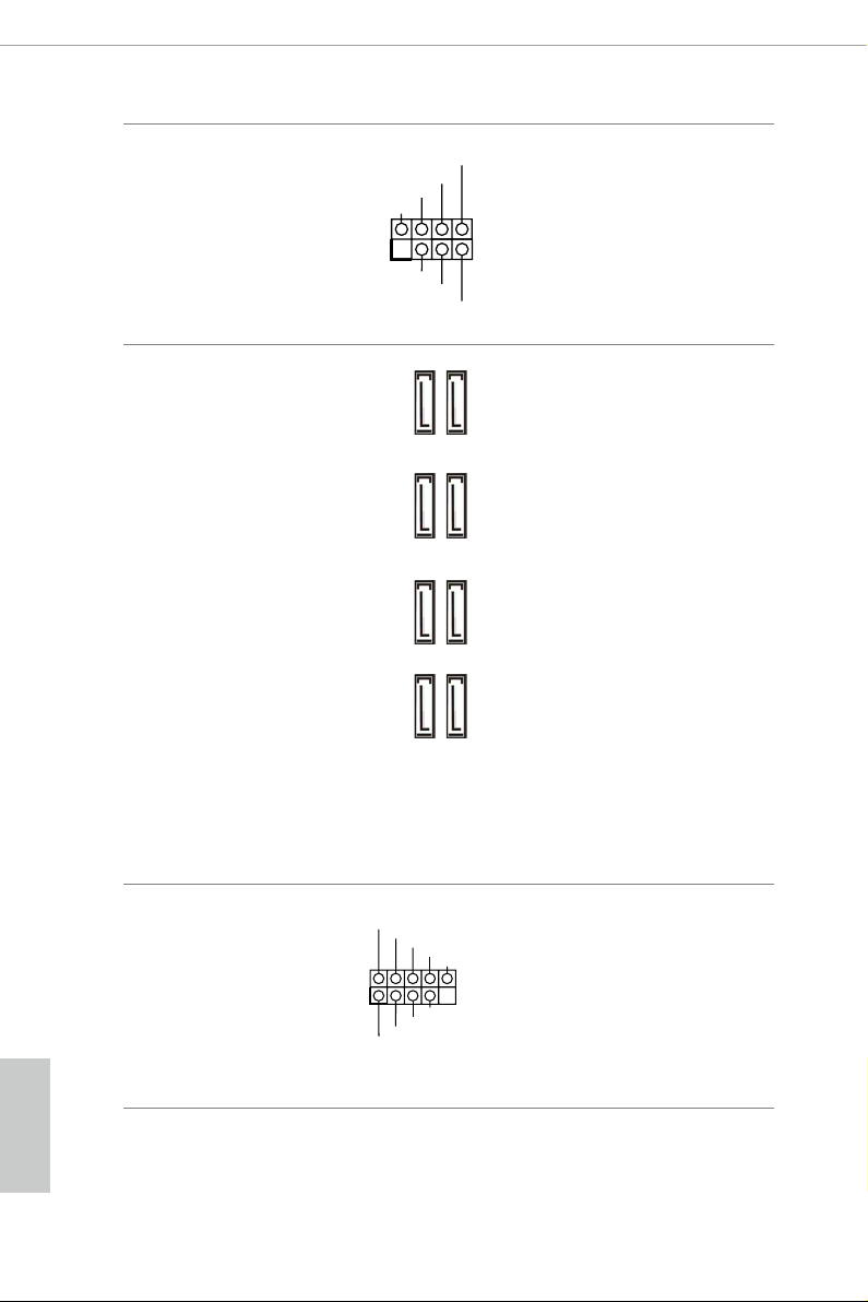
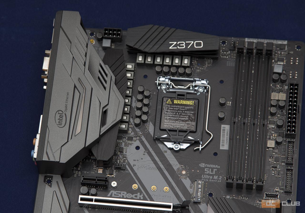
Chassis Fan Connectors
FAN_SPEED_CONTROL
1 2 3 4
(4-pin CHA_FAN1)
(see p.8, No. 27)
(4-pin CHA_FAN2)
(see p.8, No. 22)
AN_SPEED_CONTROL
CHA_FAN_SPEED
FAN_VOLTAGE
FAN_VOLTAGE
FAN_SPEED
FAN_SPEED_CONTR
1 2 3 4
Please connect fan cables
to the fan connectors and
match the black wire to
the ground pin.
GN
Chassis Optional/Water
Pump Fan Connector
(4-pin CHA_FAN3/W_
PUMP)
(see p.8, No. 16)
CPU Fan Connector
(4-pin CPU_FAN1)
(see p.8, No. 2)
CPU Optional/Water
Pump Fan Connector
(4-pin CPU_OPT/W_
PUM P)
(see p.8, No. 3)
D
FAN_VOLTAGE
FAN_SPEED
FAN_SPEED_CONTR
1 2 3 4
CPU_FAN_SPEED
FAN_VOLTAGE
GND
N_SPEED_CONTROL
CPU_FAN_SPEED
FAN_VOLTAGE
GND
is motherboard
provides a 4-Pin water
cooling
chassis
connectors. If you plan to
connect a 3-Pin
water cooler fan, please
connect it to Pin 1-3.
is motherboard
provides a 4-Pin CPU fan
(Quiet Fan) connector.
If you plan to connect a
3-Pin CPU fan, please
connect it to Pin 1-3.
is motherboard
4
provides a 4-Pin water
3
2
cooling CPU fan
1
connector. If you plan
to connect a 3-Pin CPU
water cooler fan, please
connect it to Pin 1-3.
fan
chassis
English
24
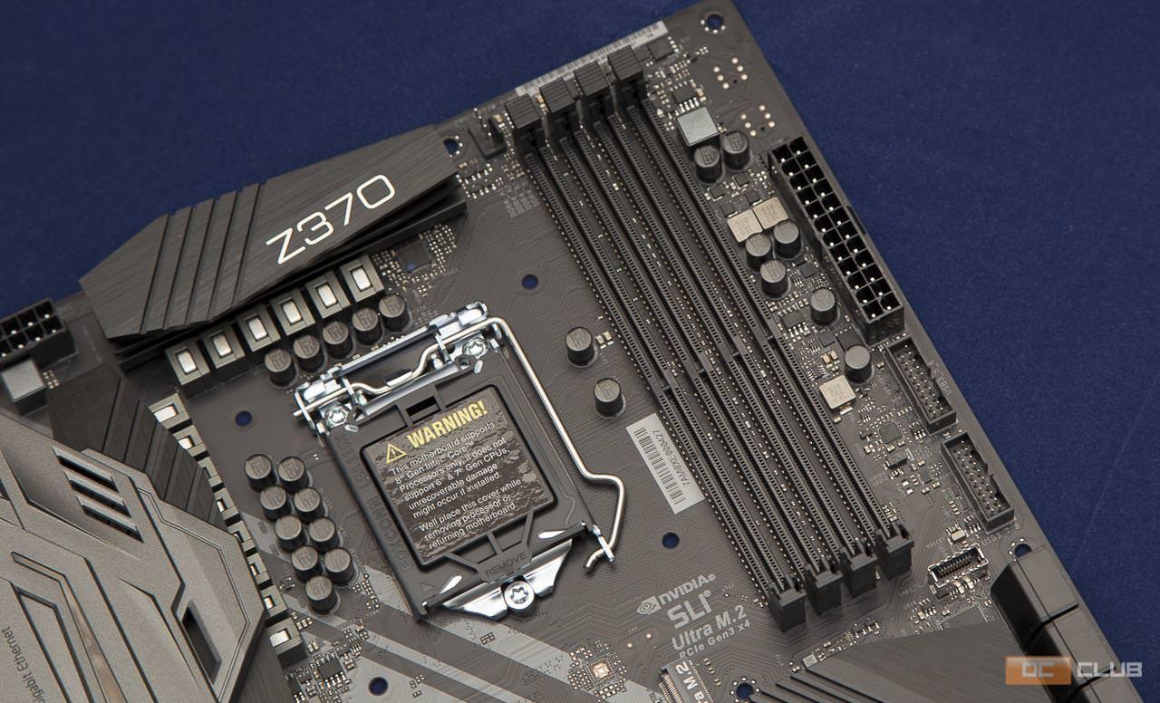
ATX Power Connector
(24-p i n ATX PWR1)
(see p.8, No. 6)
12
24
is motherboard pro-
vides a 24-pin ATX power
connector. To use a 20-pin
ATX power supply, please
plug it along Pin 1 and Pin
1
13
13.
Loading…
Asrock Z370 Extreme4
View the manual for the Asrock Z370 Extreme4 here, for free. This manual comes under the category motherboards and has been rated by 1 people with an average of a 9.5.
This manual is available in the following languages: English. Do you have a question about the Asrock Z370 Extreme4 or do you need help?
Ask your question here
Product Images (8)

Asrock Z370 Extreme4 specifications
Below you will find the product specifications and the manual specifications of the Asrock Z370 Extreme4.
The Asrock Z370 Extreme4 is a motherboard designed to support both HDD and SSD storage drive types, making it versatile and suitable for various storage needs. It comes with four DIMM memory slots, allowing for a maximum internal memory capacity of 64 GB. The motherboard does not support ECC memory, but it does support memory clock speeds of 2133 and 4333 MHz. The Intel Extreme Memory Profile (XMP) feature is also supported, providing enhanced memory performance.
This motherboard is compatible with Intel processors, specifically those in the Core i3, Core i5, and Core i7 series. It is also capable of supporting discrete graphics cards, making it suitable for gaming or graphics-intensive tasks. The graphics card family supported by this motherboard is Intel.
When it comes to operating systems, the Asrock Z370 Extreme4 is compatible with Windows. It provides a reliable and stable platform for running Windows-based applications.
Constructed with high-quality materials, this motherboard ensures durability and longevity. It is a reliable choice for users seeking a motherboard that can support their storage and memory needs efficiently. The Asrock Z370 Extreme4 offers a range of features and capabilities that make it a suitable option for various computing purposes.
Supported memory types
DDR4-SDRAM
Supported storage drive types
HDD & SSD
Intel Extreme Memory Profile (XMP)
Yes
Windows operating systems supported
Yes
Processor manufacturer
Intel
Graphics card family
Intel
General
| Brand | Asrock |
| Model | Z370 Extreme4 | 90-MXB5U0-A0UAYZ |
| Product | motherboard |
| Language | English |
| Filetype | User manual (PDF) |
Memory
| Supported memory types | DDR4-SDRAM |
| Memory slots type | DIMM |
| Number of memory slots | 4 |
| Supported memory clock speeds | 2133,4333 MHz |
| Memory channels | Dual-channel |
| Maximum internal memory | 64 GB |
| Unbuffered memory | Yes |
Storage controllers
| Supported storage drive types | HDD & SSD |
| Supported storage drive interfaces | M.2, SATA III |
| RAID levels | 0, 1,5, 10 |
Processor special features
| Intel Extreme Memory Profile (XMP) | Yes |
| Intel® Optane™ Memory Ready | Yes |
Features
| Windows operating systems supported | Yes |
| Component for | PC |
| Motherboard chipset family | Intel |
| Motherboard chipset | Intel® Z370 |
| Motherboard form factor | ATX |
| Audio output channels | 7.1 channels |
| Cooling type | Passive |
| PC health monitoring | CPU, FAN, Power supply, Temperature, Voltage |
| Audio chip | Realtek ALC1220 |
| Power source type | ATX |
| Certification | FCC, CE, ErP/EuP ready |
Processor
| Processor manufacturer | Intel |
| Compatible processor series | Intel Core i3, Intel Core i5, Intel Core i7 |
| Processor socket | LGA 1151 (Socket H4) |
| Maximum number of SMP processors | 1 |
| Supported processor sockets | LGA 1151 (Socket H4) |
Graphics
| Graphics card family | Intel |
| Discrete graphics support | Yes |
| Parallel processing technology support | 2-Way CrossFireX, 2-Way SLI, 3-Way CrossFireX, Quad-GPU CrossFireX, Quad-GPU SLI |
| DirectX version | 12.0 |
| Maximum resolution | 4096 x 2160 pixels |
Internal I/O
| USB 2.0 connectors | 3 |
| USB 3.2 Gen 2 (3.1 Gen 2) connectors | 0 |
| USB 3.2 Gen 1 (3.1 Gen 1) connectors | 3 |
| Number of SATA connectors | 8 |
| ATX Power connector (24-pin) | Yes |
| CPU fan connector | Yes |
| Front panel audio connector | Yes |
| Front panel connector | Yes |
| Number of Parallel ATA connectors | 0 |
| Number of SATA II connectors | 0 |
| Number of SATA III connectors | 8 |
| Number of COM connectors | 1 |
| Number of chassis fan connectors | 2 |
| TPM connector | Yes |
| EPS power connector (8-pin) | Yes |
| Thunderbolt headers | 1 |
BIOS
| BIOS type | UEFI |
| BIOS memory size | 16 Mbit |
| ACPI version | 6.0 |
| System Management BIOS (SMBIOS) version | 2.7 |
Rear panel I/O ports
| USB 2.0 ports quantity | 0 |
| USB 3.2 Gen 1 (3.1 Gen 1) Type-C ports quantity | 0 |
| USB 3.2 Gen 1 (3.1 Gen 1) Type-A ports quantity | 4 |
| USB 3.2 Gen 2 (3.1 Gen 2) Type-A ports quantity | 1 |
| Ethernet LAN (RJ-45) ports | 1 |
| USB 3.2 Gen 2 (3.1 Gen 2) Type-C ports quantity | 1 |
| Headphone outputs | 1 |
| eSATA ports quantity | 0 |
| Microphone in | Yes |
| PS/2 ports quantity | 1 |
| HDMI ports quantity | 1 |
| DVI-D ports quantity | 1 |
| VGA (D-Sub) ports quantity | 1 |
| Firewire (IEEE 1394) ports | 0 |
| S/PDIF out port | Yes |
| WiFi-AP antenna jack | 2 |
Network
| Ethernet LAN | Yes |
| Ethernet interface type | Gigabit Ethernet |
| Wake-on-LAN ready | Yes |
| LAN controller | Intel® I219-V |
Weight & dimensions
Expansion slots
| PCI Express x1 (Gen 3.x) slots | 3 |
| PCI Express x16 (Gen 3.x) slots | 3 |
| Number of M.2 (M) slots | 2 |
Other features
| Number of M.2 (E) slots | 1 |
| Quick installation guide | Yes |
Packaging content
| Cables included | SATA |
| Drivers included | Yes |
Logistics data
| Harmonized System (HS) code | 84733020 |
show more
Frequently Asked Questions
Can’t find the answer to your question in the manual? You may find the answer to your question in the FAQs about the Asrock Z370 Extreme4 below.
Does the Asrock Z370 Extreme4 support both HDD and SSD storage drive types?
Yes, the Asrock Z370 Extreme4 supports both HDD and SSD storage drive types, providing users with flexibility in storage solutions.
How many memory slots does the Asrock Z370 Extreme4 have?
The Asrock Z370 Extreme4 has 4 DIMM memory slots, allowing for a maximum internal memory of 64 GB, which is higher than many comparable products.
Does the Asrock Z370 Extreme4 support Intel Extreme Memory Profile (XMP)?
Yes, the Asrock Z370 Extreme4 supports Intel Extreme Memory Profile (XMP), allowing for easy overclocking of memory speeds for improved performance.
Is ECC (Error-Correcting Code) memory supported by the Asrock Z370 Extreme4?
No, ECC memory is not supported by the Asrock Z370 Extreme4, which may be a drawback for users who require advanced error correction capabilities.
What processor socket does the Asrock Z370 Extreme4 use?
The Asrock Z370 Extreme4 uses the LGA 1151 (Socket H4) processor socket, making it compatible with Intel Core i3, i5, and i7 processors, providing users with a wide range of processor options.
How can I troubleshoot issue 1 mentioned on page 23 of the manual?
To troubleshoot issue 1 mentioned on page 23 of the Asrock Z370 Extreme4 manual, follow these steps:
1. Check the connections of all components, ensuring they are securely plugged in.
2. Verify that the power supply is functioning correctly and providing adequate power to the motherboard.
3. Inspect the CPU and ensure it is properly seated in the socket without any bent pins.
4. Check the RAM modules for proper installation and compatibility with the motherboard.
5. Reset the BIOS settings to default by clearing the CMOS.
6. Update the motherboard’s BIOS to the latest version to address any compatibility issues.
7. Test the system with minimal components connected to isolate the faulty hardware.
8. If the issue persists, consult the manufacturer’s support for further assistance.
How do I resolve the problem mentioned on page 19 of the manual related to English14?
To resolve the problem mentioned on page 19 of the Asrock Z370 Extreme4 manual related to English14, follow these steps:
1. Check the connections of the components mentioned in English14 on page 19.
2. Ensure that all cables are securely plugged into their respective ports.
3. Verify that the components are compatible with the motherboard.
4. Restart the system and check if the issue persists.
5. If the problem continues, consult the troubleshooting section of the manual for further assistance.
What is the width of the Asrock Z370 Extreme4?
The Asrock Z370 Extreme4 has a width of 244 mm.
What is the depth of the Asrock Z370 Extreme4?
The Asrock Z370 Extreme4 has a depth of 305 mm.
What certifications does the Asrock Z370 Extreme4 have?
The Asrock Z370 Extreme4 has the following certifications: FCC, CE, ErP/EuP ready.
Is the manual of the Asrock Z370 Extreme4 available in English?
Yes, the manual of the Asrock Z370 Extreme4 is available in English .
Is your question not listed? Ask your question here
Внешний вид и особенности
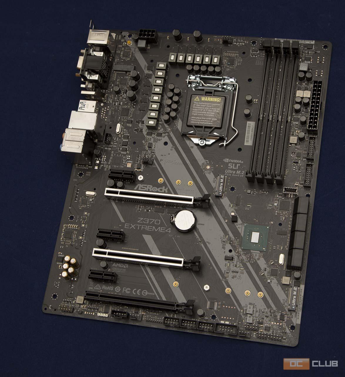
Дизайн платы довольно минималистский, чего, как по мне, в последнее время уж явно не в избытке на рынке материнок, а зря. Да, очень многим нравится, когда каждый сантиметр напоминает новогоднюю гирлянду, но не в каждой же модели-то это делать. Впрочем, и на данной плате некоторые элементы имеют RGB-подсветку, но по минимуму. В качестве основных тонов используются чёрно-серые оттенки. Вид изделия в целом довольно сдержанный, но в то же время достаточно стильный и приятный для глаза.
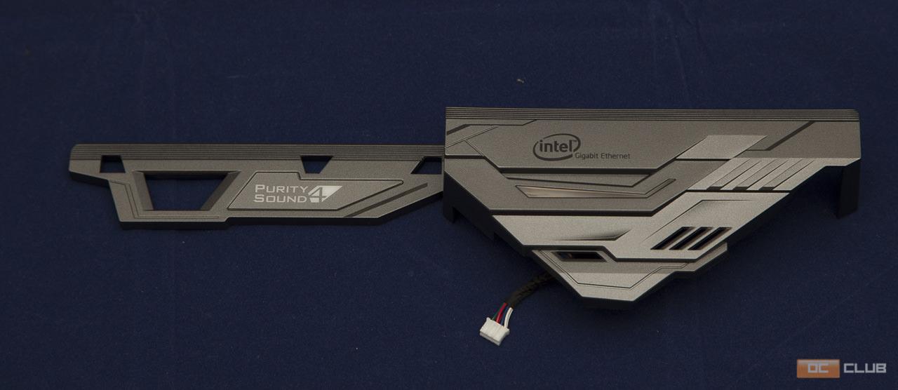
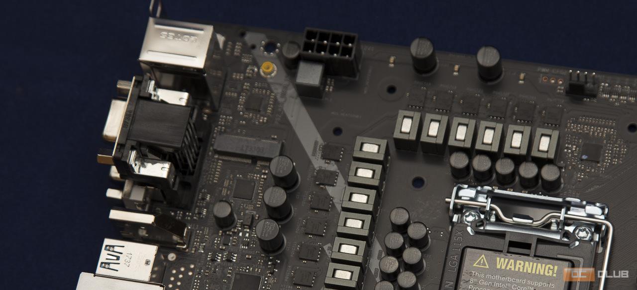
Именуемая обычно задней, хоть фактически она и расположена сбоку, панель входов/выходов полностью закрыта кожухом, который тянется до самого низа. Небольшое окошко под надписью «Intel Gigabit Ethernet» оснащено вышеупомянутой подсветкой. Под кожухом, как и сверху платы, расположены алюминиевые радиаторы, отвечающие за отвод тепла от VRM-Узла процессора. Подробнее к питанию CPU мы ещё вернёмся немного позже.
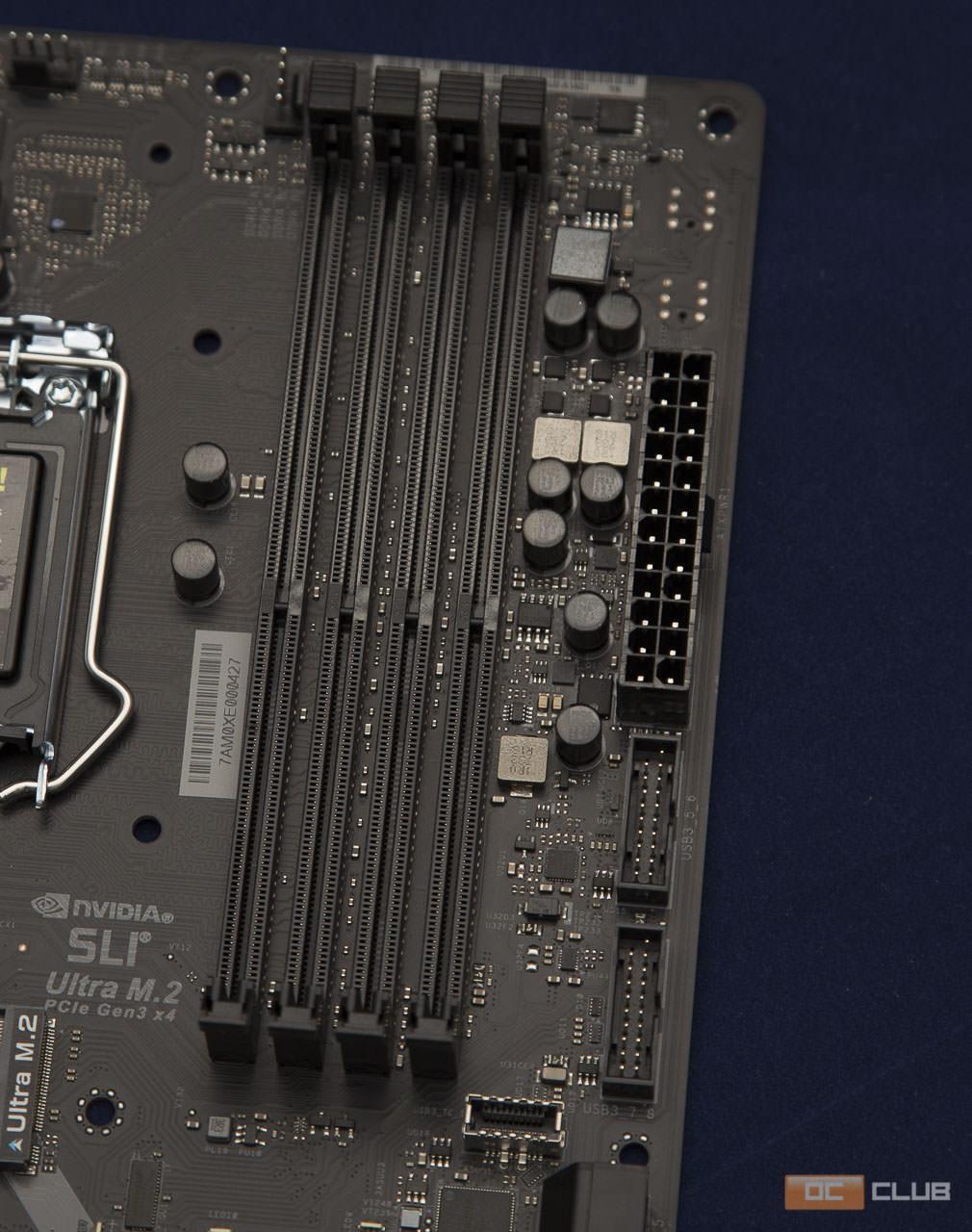
Справа, как обычно, расположились 4 разъёма DIMM, т.е. для установки модулей ОЗУ на плату. Плата рассчитана на работу с конфигурацией модулей с общим объёмом до 64 ГБ и частотой работы вплоть до 4333 МГц, хоть таких наборов пока и крайне мало на рынке.
Разъёмы, разумеется, работают в двухканальном режиме. При 4-х слотах можно спокойно брать киты 2хN ГБ и не беспокоится о невозможности апгрейда в будущем. Ну или можно сразу «воткнуть» 4 планки памяти впрок, хотя при нынешней ситуации на рынке чипов памяти я бы лучше отложил такое решение до так называемых лучших времён =). Контакты разъёмов, что в последнее время стало практически нормой для данного производителя, позолочены.
Наверняка многим знакомо такое словосочетание, как «Super Alloy». У меня оно уже в принципе ассоциируется только с материнками ASRock, даже если и встречается в совершенно другом контексте. За питание памяти в данном случае отвечают Premium Memory Alloy Choke, специально разработанные для памяти, а также обладающие высокой магнитной и теплоустойчивостью. Также тут можно подметить разъёмы для подключения фронтальных USB-колодок корпуса. В распоряжении пользователя присутствует даже USB 3.1 Type-C для корпуса, который не всегда встречается даже в более дорогих платах конкурентов, за что инженерам ASRock отдельная благодарность. Не особо существенная в данном случае экономия обычно грозит некоторым корпусам потерей одной из своих наиболее полезных фич.
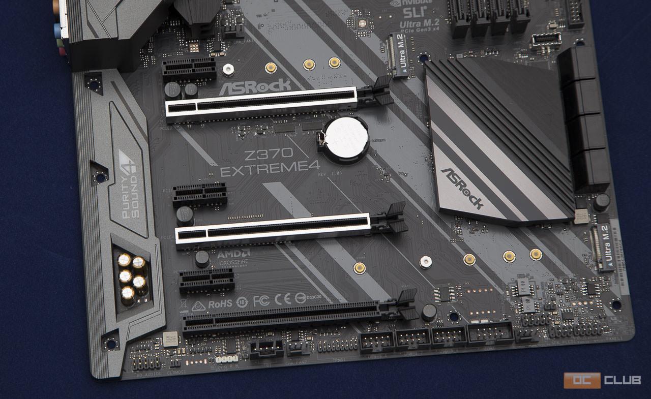
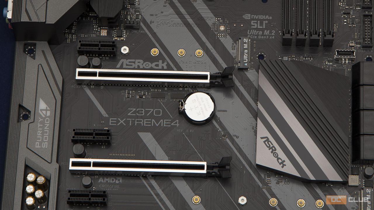
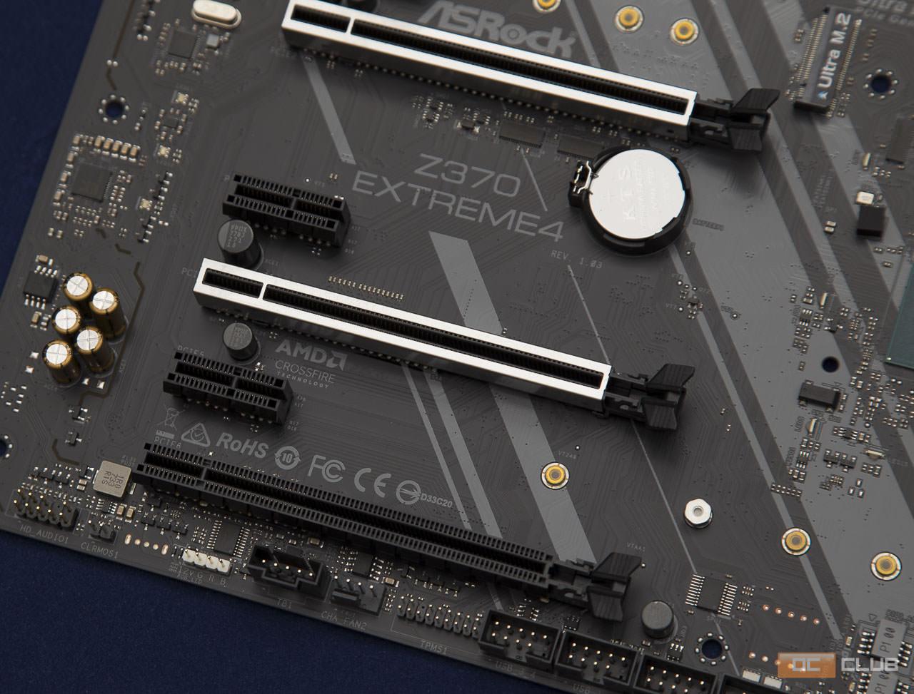
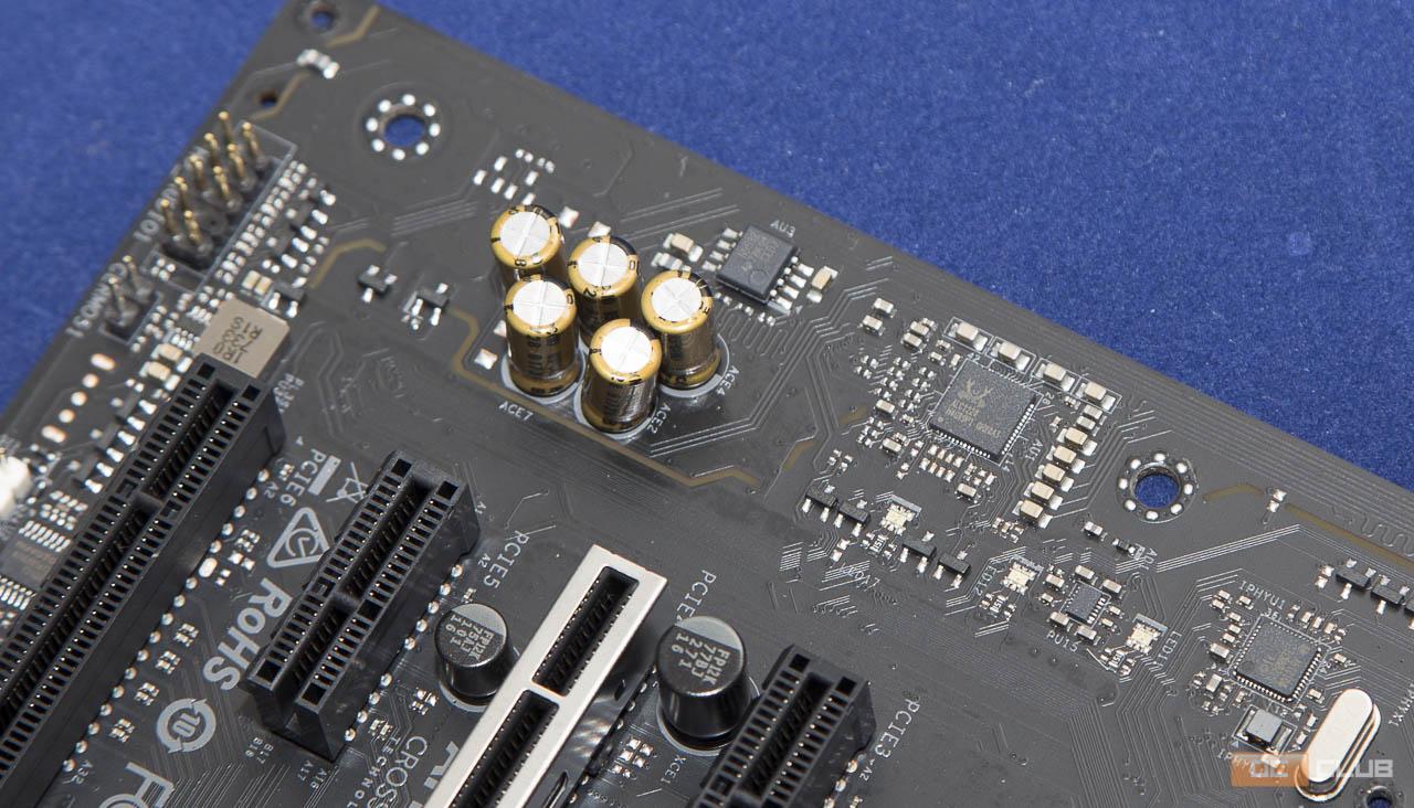
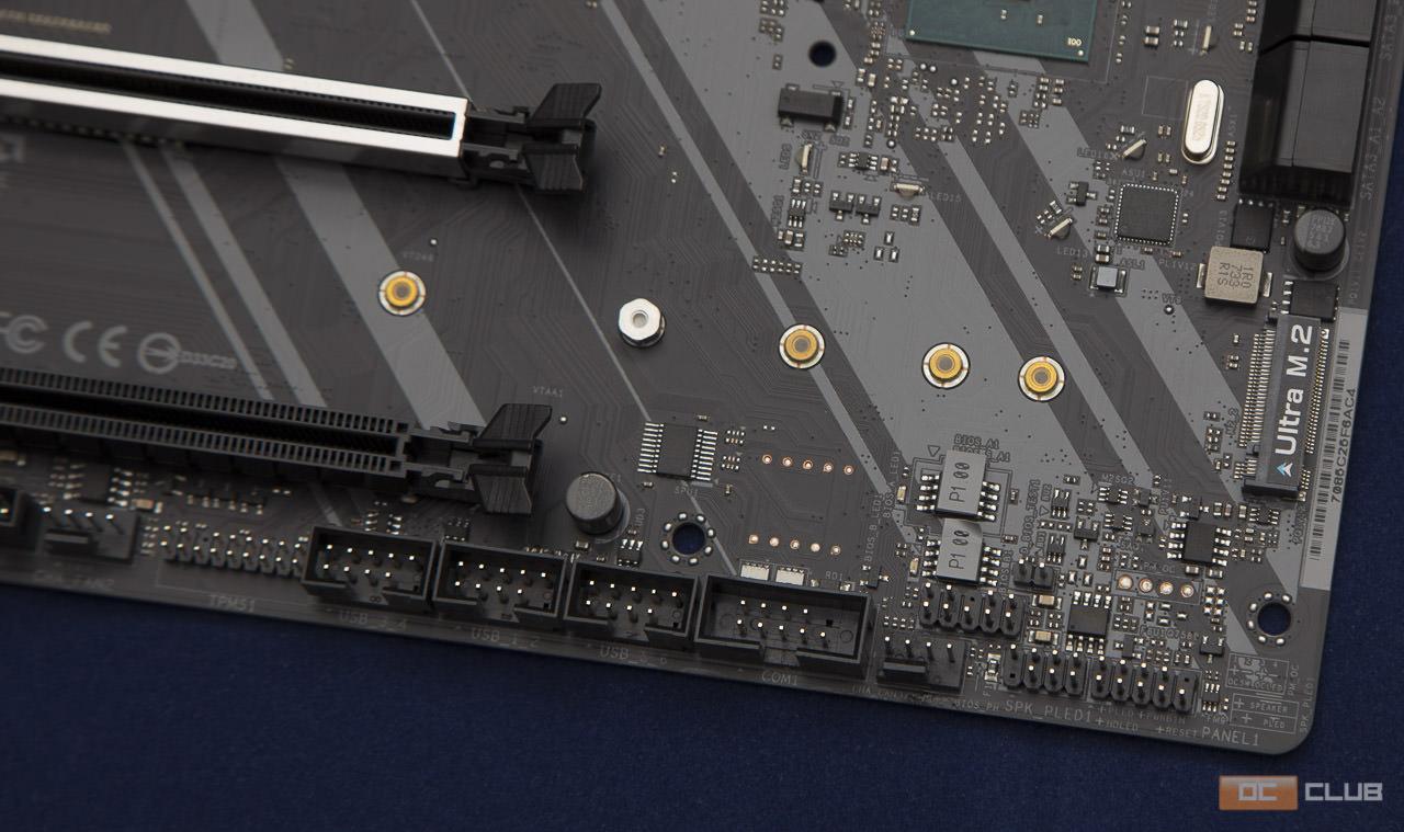
В нижней половине материнки основную долю пространства занимают разъёмы для карт расширения PCI-Express, а также пара M.2 типа Ultra, которые напрямую взаимодействуют с процессором, используя интерфейс PCI-Express, увеличивая тем самым скорость работы по сравнению с обычными М.2. контакты PCI-Express разъёмов тоже позолочены.
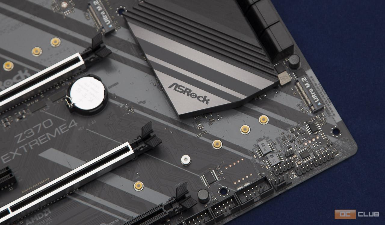
Расположение нижнего M.2 я считаю более удачным относительно своего «коллеги», поскольку даже при использовании более одной видеокарты, на него будет попадать лишь часть тёплого воздуха из них, и то не основная.
Это подводит нас к другим возможностям платы, а именно к возможности работы с несколькими видеокартами. Преимущественно речь идёт о 2-ух графических адаптерах, на что также намекает усиление 2-го и 4-го слотов. Тем не менее есть возможность использования конфигурации с 3-мя «видяхами». Фактически система будет работать в режимах х16 (PCIE2), х8 (PCIE2) / х8 (PCIE4) или же х8 (PCIE2) /х8 (PCIE4) / x4 (PCIE6) для связок из 1-й, 2-ух и 3-х карт соответственно. Также не стоит забывать, что под это дело ещё важно какой именно процессор будет выбран и сколько у него доступных линий.
Сразу под слотами расширения, в нижнем ряду всевозможных контактов, выделяется один из разъёмов белого цвета. Как по цвету, так и по подписям на самой плате не сложно обнаружить, что именно на него можно «повесить» светодиодную ленту для корпуса. К слову, таковой в комплекте обнаружено не было и в случае чего надо докупать отдельно.
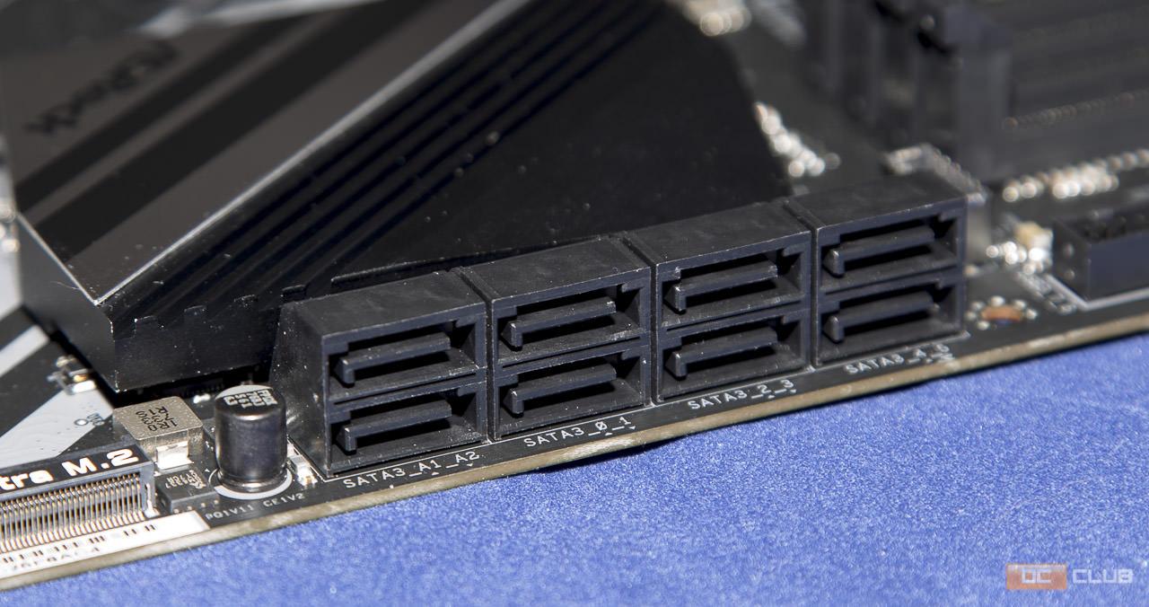
Что касается более традиционных способов организации дискового пространства, то здесь же неподалёку за это отвечают расположенные 8 портов SATA 6 ГБ/с. В совокупности с уже описанными разъёмами M.2 есть где развернуться и даже более чем.
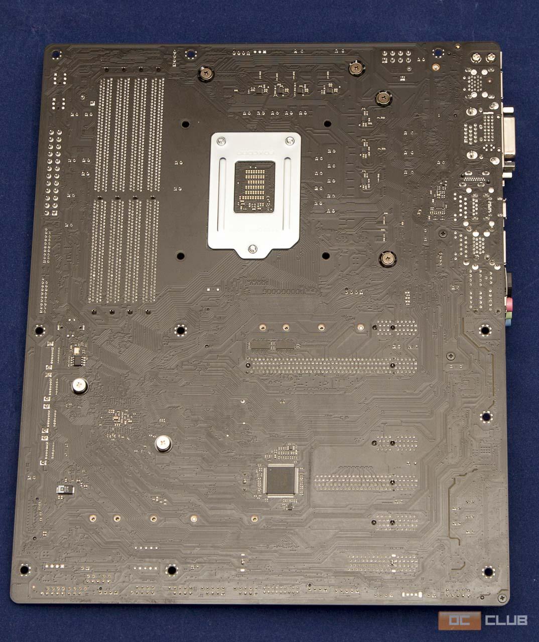
Обратная сторона не может похвастаться столь же обильным разнообразием всяких решений, как «перёд» материнки, но кое-что сюда таки вынесли. Из такого можно заметить частично расположившиеся вокруг сокета элементы узла VRM, несколько чипов и в общем-то всё. По большей части заднее пространство пустует, но так оно даже лучше, а то порой глянешь как некоторые при установке массивного кулера или оперативки вжимают плату, лежащую на твёрдой поверхности, так аж сердце замирает.
Ну, теперь можно и разобрать кое-что. А что ещё разбирать, кроме как снять радиаторы с кожухом. Радиаторы хоть и алюминиевые, но по качеству исполнения ничего особенного, такое на четвёрочку максиум. Фактически, просто пара форменных брусков из вышеупомянутого металла.
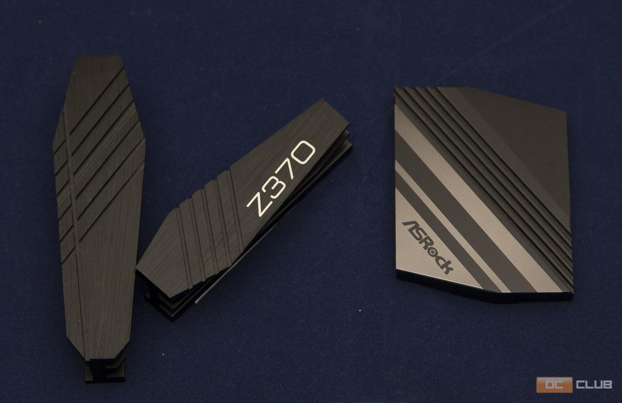
Кожух панели выходов и аудиотракта по качеству исполнения тянет примерно на ту же оценку, но при этом немного красивее и имеет 2 зоны подсветки. Свою декоративную функцию выполняет хорошо.
Избавившись от всего этого, можем узреть немного «обнаженки». Без радиаторов намного лучше видны коннекторы CPU_FAN и OPT_FAN. Последний также имеет подпись W_PUMP, что говорит о его предназначении для подключения помпы и на всякий случай рассчитан на большую нагрузку, до 1,5А. Сказать по правде, при установленном радиаторе путь к ним, особенно к основному процессорному, который используется намного чаще, не то что бы неудобный, но не самый беспрепятственный явно.
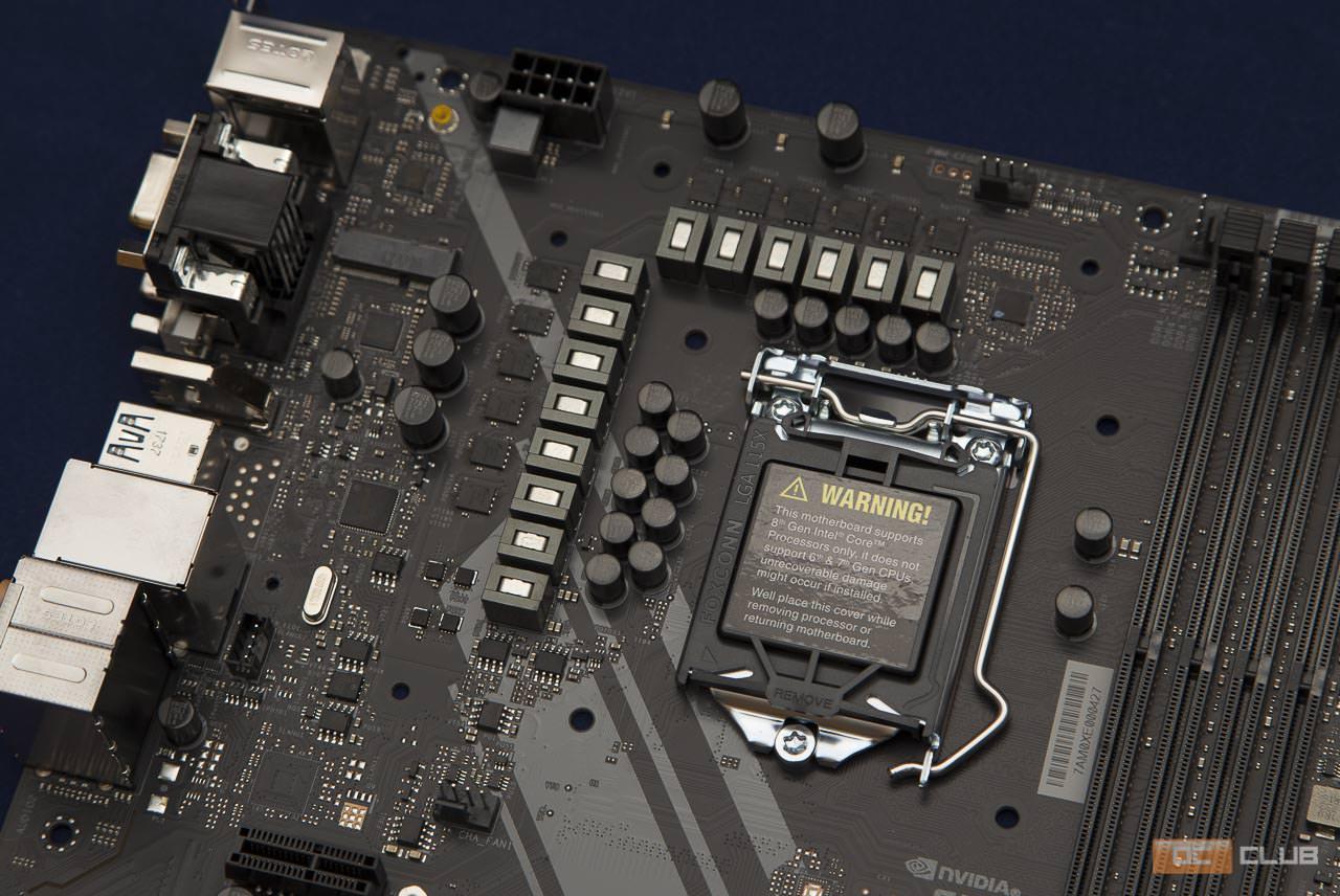
Как я и говорил выше, теперь можем детальнее рассмотреть систему питания процессора. Данная материнская плата использует 12-фазную схему, чего вполне будет достаточно даже в разгоне для 6-ядерных процессоров Coffee Lake. Приятно порадовали как исполнение, так и подобранные компоненты элементной базы. Японские конденсатор небезызвестной японской фирмы Nichicon, добротные дросселя и фирменные Dual-Stack MOSFET (DSM), разработанные компанией ASRock. Всё очень аккуратно, ничего не болтается и не отваливается. Короче говоря, придираться не к чему, идём дальше =).
Подача питания в данном случае осуществляется посредством 8-контактного разъёма.
Возле питания процессора есть ещё один довольно неприметный М.2 слот. Фактически он 3-й на плате, но предназначен он для установки WiFi-модуля с ключом типа Е.
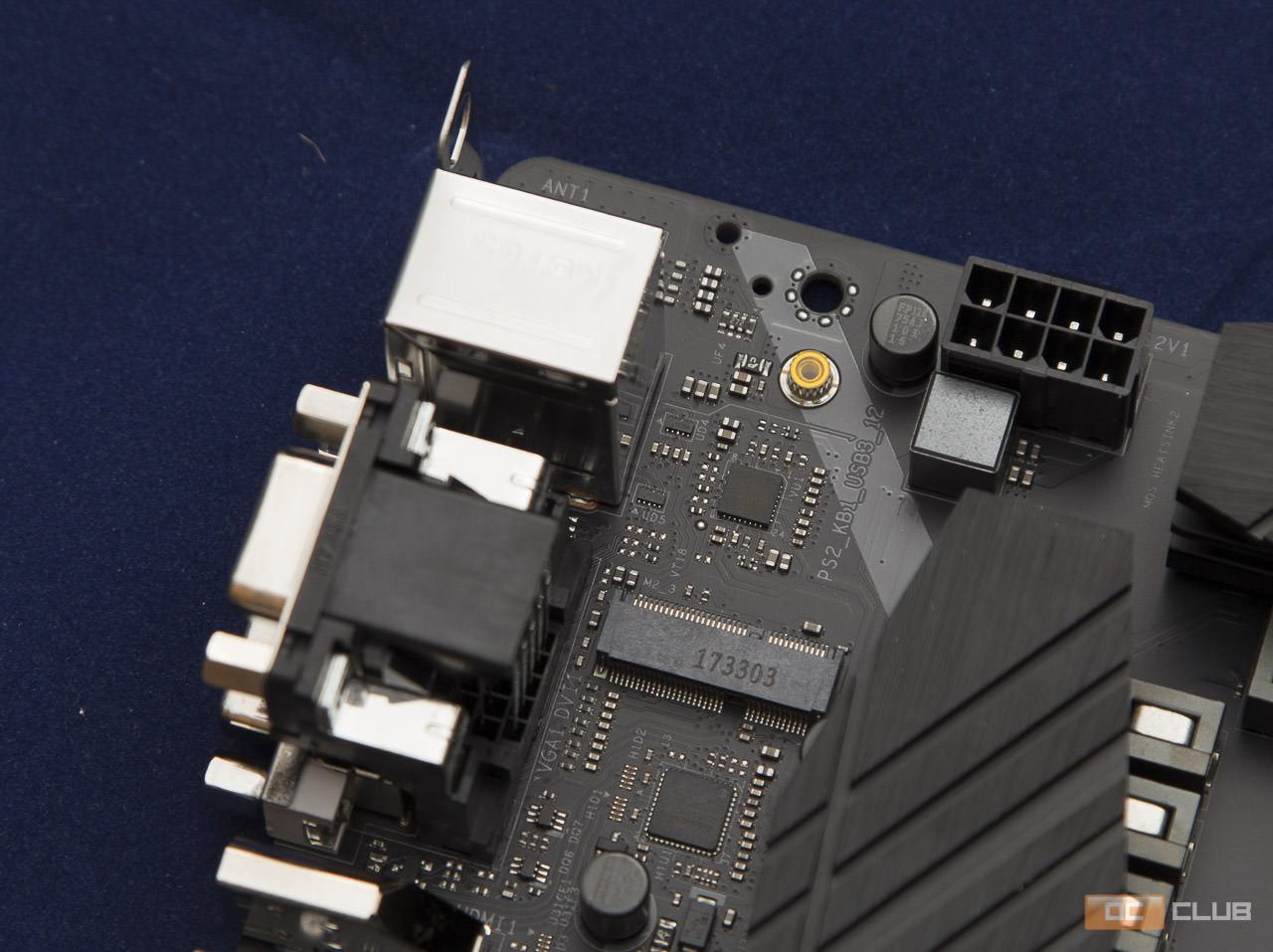
Тут же рассмотрим и панель входов/выходов. Стоит отметить, что все USB-порты, аудио разъёмы, а также Ethernet обладают защитой от резких скачков напряжения. Это, конечно, не самая жизненно необходимая из всех защит, но лишней явно не будет и в общем зачёте добавит условных баллов, пусть и не много.
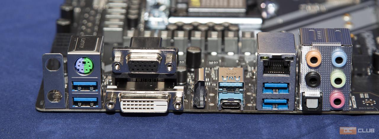
Не сказать, что панель выходов богата на количество, скорее на разнообразие. Очень радует именно широкий спектр портов, позволяющих подключать самые разнообразные устройства. Полный список таков:
- 2х Разъёма для антенн Wifi-модуля;
- 1x Комбинированный порт PS/2;
- 1x Выход D-Sub;
- 1x Выход DVI-D;
- 1x Порт HDMI;
- 1x Порт USB 3.1 Gen2 Type-A;
- 1x Порт USB 3.1 Gen2 Type-C;
- 4x Порта USB 3.1 Gen1;
- 1x Разъём RJ-45 LAN с индикаторами состояния и скорости;
- 1x Оптический выход S/PDIF;
- Набор аудио разъёмов.
Заслуживает внимания и аудиотракт данной материнки с фирменным названием Purity Sound4. Во-первых, он изолирован от остальной части печатной платы во избежание помех и использует отдельные каналы для левого и правого каналов. Во-вторых, 7.1-канальный звук на основе топового кодека Realtek ALC1220 и отличной обвязкой из вновь-таки японских конденсаторов Nichicon, но уже золотых. Кстати, все аудиовыходы также позолочены. Ну и в-третьих, в тракте присутствует усилитель для наушников. Иными словами, звук тут, как ни крути отличный и чёткий.
И, пожалуй, последнее, но ни в коем случае не по значению, что хотелось бы отметить в данном разделе: эта материнка может похвастаться очень полезной фичей в виде присутствия 2-ух BIOS’ов, дабы нерадивый юзер со слишком пытливым умом экспериментатора в случае чего не остался с «кирпичём», требующим исключительно сервисного обслуживания.
Version 1.1
Published November 2017
Copyright©2017 ASRock INC. All rights reserved.
Copyright Notice:
No part of this documentation may be reproduced, transcribed, transmitted, or
translated in any language, in any form or by any means, except duplication of
documentation by the purchaser for backup purpose, without written consent of
ASRock Inc.
Products and corporate names appearing in this documentation may or may not
be registered trademarks or copyrights of their respective companies, and are used
only for identication or explanation and to the owners’ benet, without intent to
infringe.
Disclaimer:
Specications and information contained in this documentation are furnished for
informational use only and subject to change without notice, and should not be
constructed as a commitment by ASRock. ASRock assumes no responsibility for
any errors or omissions that may appear in this documentation.
With respect to the contents of this documentation, ASRock does not provide
warranty of any kind, either expressed or implied, including but not limited to
the implied warranties or conditions of merchantability or tness for a particular
purpose.
In no event shall ASRock, its directors, ocers, employees, or agents be liable for
any indirect, special, incidental, or consequential damages (including damages for
loss of prots, loss of business, loss of data, interruption of business and the like),
even if ASRock has been advised of the possibility of such damages arising from any
defect or error in the documentation or product.
is device complies with Part 15 of the FCC Rules. Operation is subject to the following
two conditions:
(1) this device may not cause harmful interference, and
(2) this device must accept any interference received, including interference that
may cause undesired operation.
CALIFORNIA, USA ONLY
e Lithium battery adopted on this motherboard contains Perchlorate, a toxic substance
controlled in Perchlorate Best Management Practices (BMP) regulations passed by the
California Legislature. When you discard the Lithium battery in California, USA, please
follow the related regulations in advance.
“Perchlorate Material-special handling may apply, see www.dtsc.ca.gov/hazardouswaste/
perchlorate”
ASRock Website: http://www.asrock.com
Обзор материнской платы z370
Подбор правильных компьютерных комплектующих под ту или иную систему является важной задачей, от правильности решения которой зависит её быстродействие. С появлением линейки центральных процессоров (ЦП) Coffee Lake, использующих LGA1151-2 лишь немногие материнские платы (МП) могли нормально работать с этим типом ЦП.
Собственно, на момент их появления, МП на безе чипсета z370 были фактически безальтернативным вариантом подобного решения. Естественно, стоимость подобных МП была весьма высокой. Со временем ситуация изменилась, однако, до сих пор встречаются МП, имеющие стоимость порядка 500 долларов США.
На сегодняшний день ситуация существенно улучшилась, как вы ценовой политике, так и в вопросах ассортимента; в настоящий момент выбрать материнскую плату для 8-го поколения достаточно просто. Тем не менее, по своим функциональным возможностям МП на 370-м чипсете до сих пор вне конкуренции. В данной статье будет освещён вопрос выбора материнской платы для процессоров Coffee Lake.
Обзор модельного ряда Z370
Фактически чипсет Z370 отличается от своего 200-го предшественника только поддержкой новых типов ЦП, у которых немного изменён сокет (переназначено несколько контактных площадок для питания ЦП). Остальные функции не претерпели изменений.
Новая плата поддерживает главную «фишку» своего предшественника – возможность разгона ЦП по множителю, что собственно, и отражено в индексе Z. Общие характеристики 370 чипсета следующие:
- поддержка ЦП: intel core i7, i5, i3 восьмого поколения с сокетом LGA-1151-v2;
- поддержка PCIE 3.0: один х16 или 2 х8 или 1 х8 + 2 х4;
- используемая память: 64 Гб DDR4-4000 в двухканальном режиме;
- количество портов USB: 10 версии 3.0 и 14 версии 2.0;
- дисковые интерфейсы: 6 SATA 3.0 и 3 M.2;
- поддержка мониторов: EDP 1.4, HDMI 1.4, HDMI 2.0, DP 1.2;
- дополнительное питание ЦП: 8pin.
Также МП снабжена стандартным сетевым контроллером с поддержкой 1000 Мбит/с и звуковым модулем на базе ALC887.
Рассмотрим обзоры различных материнских плат на базе чипсета Z370:
MSI Z370a Pro
Один из лучших представителей недорогого сегмента. Стоимость такой материнки составляет порядка 120 долларов. Форм-фактор материнки: АТХ. На ней располагаются два слота PCIEх16 и 4 слота PCIEx1.
Конструктивно МП выполнена достаточно грамотно, поскольку на ней нет нагромождения компонентов как возле ЦП, так и непосредственно возле чипсета. Это существенно улучшает условия вентиляции компонентов.
Периферия стандартна, однако разъёмов М.2 только один.
Asrock Z370 Extreme 4
Материнка, практически полностью повторяющее референс, и имеющая все необходимые функции. При этом, её цена может быть отнесена к бюджетному сегменту. Получить за 140 долларов полноценную материнку в АТХ формате для топовых процессоров – очень даже неплохой вариант для любого пользователя. Какие-либо особенности или «изюминки» у данного решения отсутствуют, но они и не нужны – достаточно полного повторения заявленных параметров в базовой спецификации.
MSI Z370 Godlike gaming
Эта материнская плата на Z370 не только полностью повторяет референсный образец, но ещё и содержит множество дополнительных опций, касающихся в первую очередь, возможностей экстремального разгона и мониторинга состояния процессора, видеокарты, памяти и т.д.
Кроме того, по заявлениям производителя, плата обладает улучшенной подолжкой, более толстыми (и как следствие, более мощными) шинами питания, изоляцией от внешнего воздействия критически важных узлов платы и т.д.
BIOS этой материнки имеет множество настроек, а вместе с ней поставляется большое количество программного обеспечения, призванного обеспечить максимальное быстродействие в играх.
Цена – порядка 220 долларов.
Asrock Z370m Pro4
Недорогое решение в среднем ценовом сегменте с немного урезанной периферией, но с возможностью поддержки DDR4-4300. Имеет формат miniATX, поэтому размеры платы небольшие. На ней помещаются всего 4 слота PCI-express: два PCIEx16 и два PCIEx-1.
Стоимость – около 140 долларов.
Asrock Fatal1ty Z370 для игр
Одна из наиболее продвинутых материнок в настоящее время. Отличается от референсной не только большим количеством периферийных устройств, но и некоторыми принципиально новыми возможностями, что является нечастой ситуацией на рынке материнских плат.
Можно с уверенностью сказать, что эта материнка ничем не хуже аналогичной игровой от MSI.
Цена – около 250 долларов.
Z370 Lightsaber
Материнская плата ECS Z370 Lightsaber обладает стандартным набором всех устройств USB, что же касаемо периферии, то она ней присутствуют следующие компоненты:
- 6 портов SATA 3.0;
- 2 Разъёма М.2;
- 3 слота PCIEx16;
- 3 слота PCIEx1;
- аудиосистема ALC1150.
Плата снабжена радиаторами с тепловыми трубками и системой подсветки, управляемой чрез BIOS.
Отзывы
Приобрёл материнку Asrock Z370 Extreme 4, использую её уже несколько месяцев. Всё работает нормально. Особенно порадовали функции разгона. Смог разогнать свой i7 почти до 5 ГГц. Материнка адекватно реагирует на любые изменения в тепловых режимах процессора и подстраивает систему охлаждения под них практически идеально.
Использую в своём компе MSI Z370a Pro, поскольку это самое недорогое решение, которое сейчас есть на Coffee Lake. Я не сторонник чрезмерной траты средств, потому что не хочу переплачивать за 10% быстродействия 100% наценки, тем более в таком вопросе, как материнка. Но, должен сказать, несмотря на свою дешевизну, она полностью удовлетворяет потребности как процессора, так и всей периферии, которая есть у меня в системнике.
Так же вы можете прочитать статьи на темы: Характеристики Gtx 1070 и Обзор видеокарты gtx 2080
Источник
Russian, Введение, 1 комплектность – ASRock Z77 Extreme4 User Manual
Page 116: Ру сский

ASRock Z77 Extreme4 Motherboard
1. Введение
Благодарим вас за покупку материнской платы ASRock Z77 Extreme4 надежной
материнской платы, изготовленной в соответствии с постоянно предъявляемыми ASRock
жесткими требованиями к качеству. Она обеспечивает превосходную производительность
и отличается отличной конструкцией, которые отражают приверженность ASRock качеству
и долговечности.
Данное руководство по быстрой установке включает вводную информацию о материнской
плате и пошаговые инструкции по ее установке. Более подробные сведения о плате
можно найти в руководстве пользователя на компакт-диске поддержки.
Спецификации материнской платы и программное обеспечение
BIOS иногда изменяются, поэтому содержание этого руководства
может обновляться без уведомления. В случае любых модификаций
руководства его новая версия будет размещена на веб-сайте ASRock
без специального уведомления. Кроме того, самые свежие списки
поддерживаемых модулей памяти и процессоров можно найти на
Адрес веб-сайта ASRock http://www.asrock.com
При необходимости технической поддержки по вопросам данной
материнской платы посетите наш веб-сайт для получения
информации об используемой модели.
1.1 Комплектность
Материнская плата ASRock Z77 Extreme4
(форм-фактор ATX: 12,0 x 8,6 дюйма / 30,5 x 21,8 см)
Руководство по быстрой установке ASRock Z77 Extreme4
Компакт-диск поддержки ASRock Z77 Extreme4
2 x кабель данных Serial ATA (SATA) (дополнительно)
1 x I/O Щит Группы ввода / вывода
1 x карта ASRock SLI_Bridge_2S
ASRock напоминает.
Для обеспечения максимальной производительности ОС Windows
7 / 7 64-bit / Vista
64-bit рекомендуется в BIOS выбрать для
параметра Storage Configuration (Конфигурация запоминающего
устройства) режим AHCI. Подробные сведения о настройке BIOS см.
в руководстве пользователя на прилагаемом компакт-диске.
Источник
ASROCK Z370 Extreme4 Manual
ASROCK Z370 Extreme4 File Information:
ASROCK Z370 Extreme4 PDF Guide Online Viewing:
ASROCK Z370 Extreme4: Summary of Contents
| Page № | Page’s Content |
|---|---|
| 10 | |
| 115 | |
| 161 | |
| 11 | |
| 102 | |
| 147 | |
| 74 | |
| 25 | |
| 166 | |
| 111 | |
| 79 | |
| 168 | |
| 76 | |
| 92 | |
| 131 | |
| 51 | |
| 7 | |
| 33 | |
| 16 | |
| 110 | |
| 94 | |
| 104 | |
| 20 | |
| 39 | |
| 30 | |
| 151 | |
| 28 |
More Manuals for ASROCK Z370 Extreme4:
ASROCK A55iCafe Operation & user’s manual
A55iCafe, Z370 Extreme4 Operation & user’s manual (DT61V7)
ASROCK X99E-ITX/ac Operation & user’s manual
ASROCK Motherboard Operation & user’s manual, #NV779C
ASROCK H61DEL Operation & user’s manual
#9OV966: H61DEL Motherboard Operation & user’s manual
ASROCK B75M-ITX Operation & user’s manual
Motherboard Operation & user’s manual (B75M-ITX, #5X79Y6)
ASROCK WOLFDALE1333-GLAN-M2 — V1.0 Operation & user’s manual
WOLFDALE1333-GLAN-M2 — V1.0, Z370 Extreme4 Operation & user’s manual (RFQ16L)
ASROCK B85M-GL Operation & user’s manual
ASROCK Motherboard Operation & user’s manual, #3MFBO9
ASROCK 990FX EXTREME3 Quick installation manual
Motherboard Quick installation manual (990FX EXTREME3, #4L9496)
ASROCK X48TURBOTWINS-WIFI Installation manual
#B97A11: X48TURBOTWINS-WIFI Motherboard Installation manual
Источник
Обзор материнской платы ASRock Z370 Extreme4
Введение
Выход для новых многоядерных процессоров Intel нового сокета LGA1151v2 стало некоторым шоком для большинства пользователей. Теперь, при желании обновить систему до процессоров Intel core i 3/ i 5/ i 7 8-го поколения, будь любезен купить новую материнскую плату на чипсете Intel Z370. И что самое печальное – выбор на сегодняшний не очень большой, и почти все предложения – совсем не бюджетные, и потому не хочется прогадать, купив не перспективную и не пригодную для разгона модель. Сегодня протестируем одну из самых оптимальных недорогих материнских плат — ASRock Z370 Extreme4.
Внешний вид ASRock Z370 Extreme4
Не соврём, если скажем, что ASRock всегда сталась идти в ногу со временем и удовлетворять все основные потребности, а иногда и предлагая то, на что не решались другие производители. И в случае с Z370 Extreme4 бренд не стал идти против себя и за относительно небольшие деньги предлагает очень интересную материнскую плату, в которой учтены практически все современные тенденции. Но давайте по порядку.
Встречают по одёжке, а потому особенно интересно, что из коробки материнская плата извлекается с пристёгнутым пластиковыми стяжками мягким поддоном для защиты от повреждений в процессе транспортировки. Согласитесь – такая забота не может не радовать.
Чёрный текстолит с серыми элементами сегодня в моде. Это позволяет при создании системы с прозрачным окном в боковой стенке корпуса заострять внимание на элементах системы, а не на самой материнской плате. Хотя и у неё есть на что посмотреть.
В первую очередь предлагаю взглянуть на набор портов на задней панели. Идём справа налево: аудиовыходы 7.1 канальной встроенной звуковой карты, включая оптический аудио-выход, два USB 3.1 Gen1, гигабитный сетевой порт RJ 45, два USB 3.1 Gen2 (один из них – Type C ), видеовыходы при использовании встроенного в процессор видеоядра ( VGA , DVI , HDMI ), ещё пара USB 3.1 Gen1, комбинированный разъём PS /2 для мышки или клавиатуры, а также два отверстия для опционального Wi — Fi модуля, который вставляется в слот M.2 (KEY E), находящийся с обратной стороны панели.
В ASRock Z370 Extreme4 используется 12 фаз питания, десять из которых питают процессор, ещё две – встроенное в него видео ядро. В достоинства производитель также относит применение технологии Dual-Stack MOSFET, которая используется для повышения эффективности питания и снижения сопротивления путём объединения в одном корпусе полевого транзистора двух кремниевых подложек. Плюс не могут не радовать внушительные радиаторы охлаждения на цепях питания.
Источник