
Installation
Back-UPS
™
CS
350/500
User’s Manual
990-2085 2/01
1
Placement / Power
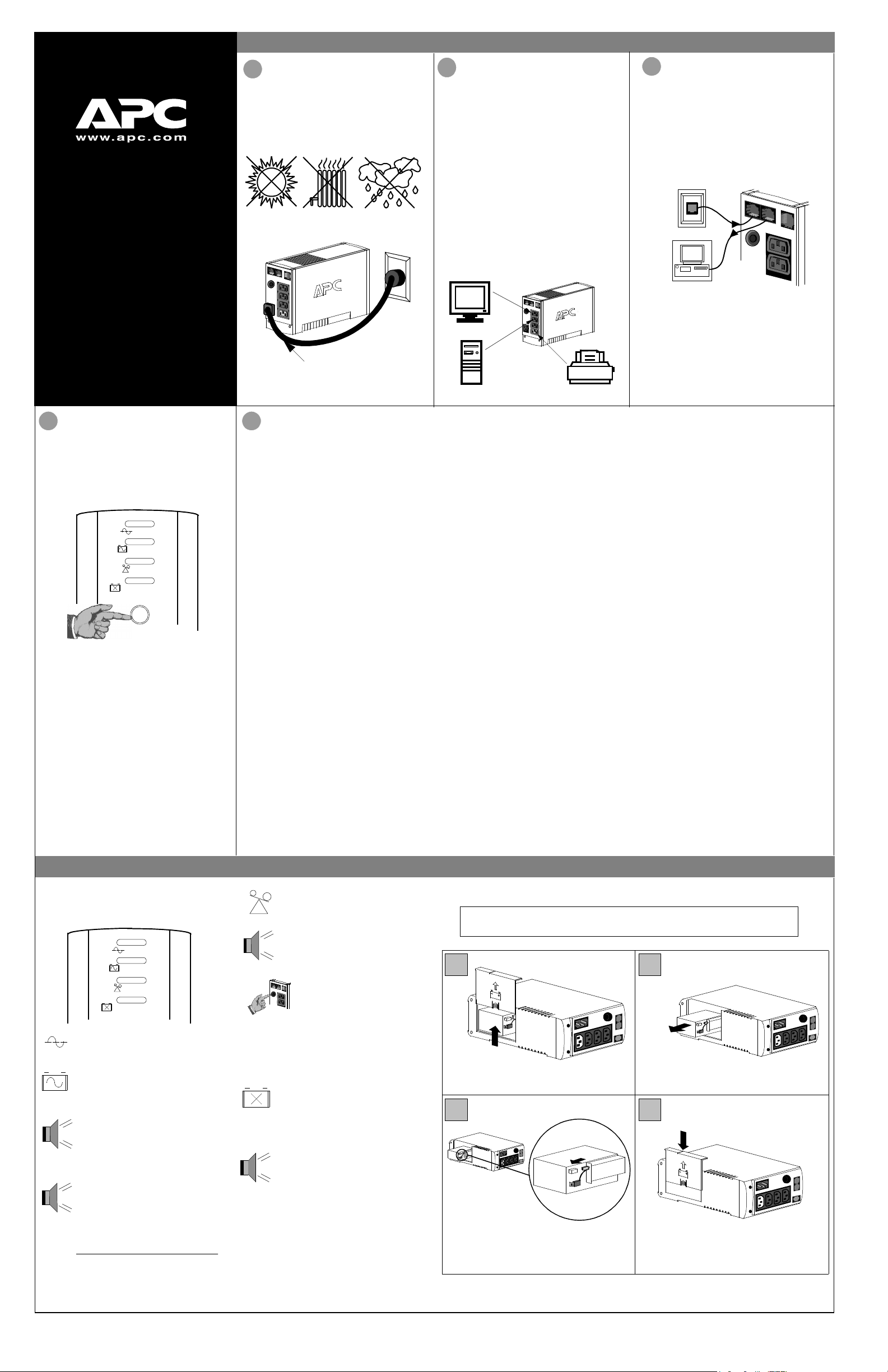
Avoid placing the Back-UPS in:
®
• Direct sunlight
• Excessive heat
• Excessive humidity or in contact with fluids
of any type
Plug the Back-UPS into a wall outlet, as shown.
2
Connect Equipment
to the Back-UPS
The rear panel of the Back-UPS consists of the
following elements:
Battery Back Up Outlets (qty. of 3). These
outlets provide battery back-up, surge protection,
and Electro-magnetic Interference (EMI) filtering.
In case of power outage, battery power is
automatically provided to these outlets. Power
(utility or battery) is not supplied to these outlets
when the Back-UPS is switched Off. Connect a
computer, monitor, and external disk or CD-ROM
drive to these outlets.
Surge Only Outlet. This outlet is always On
(when utility power is available) and is not
controlled by the On/Off switch. This outlet does
not provide power during a power outage. Connect
a printer, fax machine or scanner to this outlet.
3
Connect the Phone
Line to Surge Protection
The telephone ports provide lightning surge
protection for any device connected to the telephone
line (computer, modem, fax or telephone). The
telephone ports are compatible with Home Phoneline
Networking Alliance (HPNA) and Digital Suscriber
Line (DSL) standards, as well as all modem data
rates. Connect as shown.
Wall Outlet
Modem/Phone/Fax
Your computer’s power cord.
• The Back-UPS charges the internal battery
any time it is connected to a wall outlet.
4
Switch on the
Back-UPS
Note: Allow the Back-UPS to charge for a full eight
hours prior to use.
Press the push-button on the front panel of the BackUPS.
ON LINE
ON BATTERY
OVERLOAD
REPLACE BATTERY
Observe that the following events occur after
pressing and releasing the push-button:
• The green On-Line indicator flashes.
• The yellow On Battery indicator lights while
the Self-Test is being performed.
• When Self-Test has successfully completed,
only the green On Line indicator will be lit.
• If the internal battery is not connected, (see Step
1 above) the green On Line indicator and red
Replace Battery indicator will light. The BackUPS will also emit a chirping sound.
5
Connect USB Cable and Install Software (optional)
Note: The Back-UPS software CD-ROM provides
data reporting and unattended shutdown of
computers connected to the device. The User’s
Guide contains additional information about the
Back-UPS software. The User’s Guide is
contained in the main folder with the CD-ROM.
Attention: USB Hubs
The Back-UPS should be plugged into the USB
port of the computer, not into a USB hub.
The computer must be powered On before
connecting the USB cable. Connect the USB cable
end (USB symbol facing down) to the rear panel
USB port of the Back-UPS. Connect the other end
of the USB cable to the USB port (usually located
on the rear panel of the computer).
®
Windows 98
The APC Power Management Extensions
software has been designed specifically to work
with Windows 98 build number 4.10.1998,
Windows 98 SE (Second Edition) 4.10.2222A,
and Windows Me (Millennium Edition).
To ascertain the build number, go to the Control
Panel, open the System dialog and view the
System information under the General tab of the
dialog. To install the software, perform the
following steps:
1. Please skip to step 4 if running Windows Me.
For Windows 98, after connecting the USB
cable, the “Add New Hardware Wizard” dialog
box is displayed. Insert a Windows 98 operating
system CD into the computer CD-ROM drive
before proceeding.
2. Follow the installation instructions on the
computer screen.
During installation, Windows will need to
search for new drivers. When prompted, make
sure the CD-ROM drive box is checked.
and Windows Me® Users
3. After installation of the drivers is complete, a
“Windows 98 CD-ROM” dialog box may
appear. If this happens, just close the box.
4. Insert the APC Installation CD-ROM into the
computer’s drive. The software user
documentation is a file on the main folder of
the CD. The filename is Users Guide.pdf.
5. Follow the installation instructions on the
computer screen.
If the software does not automatically install,
the Windows autorun feature may have been
disabled. In this case: Choose “Start” in the
taskbar and then the “Run” option. Type the
following: <CD-ROM drive letter>:\setup.exe.
Click “OK”.
6. After the installation is complete, the APC plug
icon will appear in the taskbar (near the clock).
To view the Power Management user interface,
double-click on the APC plug taskbar icon or,
alternatively, choose: Start > Settings >
Control Panel > Power Management.
Note: Windows 98 and Windows Me categorize a
UPS as an HID (Human Interface Device). The
Back-UPS is listed in: Control Panel > System >
Device Manager > HID category > HID
Compliant Device.
Windows 2000
The CD-ROM included with this package
contains a “wizard” that optimizes a computer
system’s power settings for operation with the
Back-UPS. It does this by changing various
settings in Power Options Properties in the
Control Panel. APC strongly advises that the
computer system be reconfigured by running this
wizard.
1. Insert the APC Power Management CD-ROM
into the computer’s drive.
2. Choose “Start” and then the “Run” option.
Type: <CD-ROM drive letter>:\setup.exe.
®
Users
Mac OS 9 (9.0.4 or higher) Users
APC Shutdown Manager software has been designed
specifically to work with Mac OS 9 (9.0.4 or higher,
except OS X). There are builds of the Mac OS prior to
Mac OS 9.0.4 with power drivers that have known
problems. Ensure that the most up to date version of
Mac OS 9 (9.0.4 or higher) is installed on the system.
Insert the APC Installation CD-ROM with the APC
Shutdown Manager software into the CD-ROM drive.
An icon called “APC Shutdown Manager v1.0” will
appear on the computer desktop. Open the folder and
double-click the “ReadMe” file. Ensure that the
computer’s hardware matches the requirements stated
in the ReadMe file. Double-click on “APC Shutdown
Manager v1.0” to begin the installation of the
software. At the first dialog, click on “Continue”.
Read the displayed license agreement and click
“Accept” to agree to the terms. Click on “Install” to
begin. After installation, click on the “Restart” dialog
button to restart the computer.
All Other Users
The software is designed for the Windows and
Macintosh operating systems mentioned in this
section. If one of these operating systems is not
installed on the computer, the Back-UPS will still
provide these primary features:
• Battery backup, surge protection, and telephone
line protection to protect the entire desktop from
lightning and power surges.
• Runtime needed to work through brief power
disturbances. This allows time to manually save
data and shut down safely.
The disabled features include Unattended Automatic
Operating System Shutdown and Application Data
Saving.
Status Indicators and Alarms
There are four status indicators (lights) on the front
panel of the Back-UPS (On Line, On Battery,
Overload, and Replace Battery).
ON LINE
ON BATTERY
OVERLOAD
REPLACE BATTERY
On Line (green) — is lit whenever utility
power is powering the Battery Backup
outlets.
On Battery (yellow) — is lit whenever
the battery of the Back-UPS is powering
equipment connected to the Battery
Backup Outlets.
Four Beeps Every 30 Seconds — this
alarm is sounded whenever the BackUPS is running On Battery. Consider
saving work in progress.
Continuous Beeping — this alarm is
sounded whenever a low battery
condition is reached. Battery run-time
is very low. Promptly save any work
in progress and exit all open
applications. Shutdown the operating
system, computer and the Back-UPS.
Overload (red) — is lit whenever
power demand has exceeded the capacity of the Back-UPS.
Continuous Tone — this alarm is
sounded whenever the Battery Backup
outlets are overloaded.
Circuit Breaker — the circuit
breaker button located on the rear
panel of the Back-UPS will stick
out if an overload condition forces
the Back-UPS to disconnect itself
from utility power. If the button
sticks out, disconnect nonessential equipment. Reset the
circuit breaker by pushing the
button inward.
Replace Battery (red) — is lit when-
ever the battery is near the end of its useful life, or if the battery is not connected
(see above). A battery that is near the
end of its useful life has insufficient runtime and should be replaced.
Chirps for 1 Minute Every 5 Hours this alarm is sounded whenever the
battery has failed the automatic
diagnostic test.
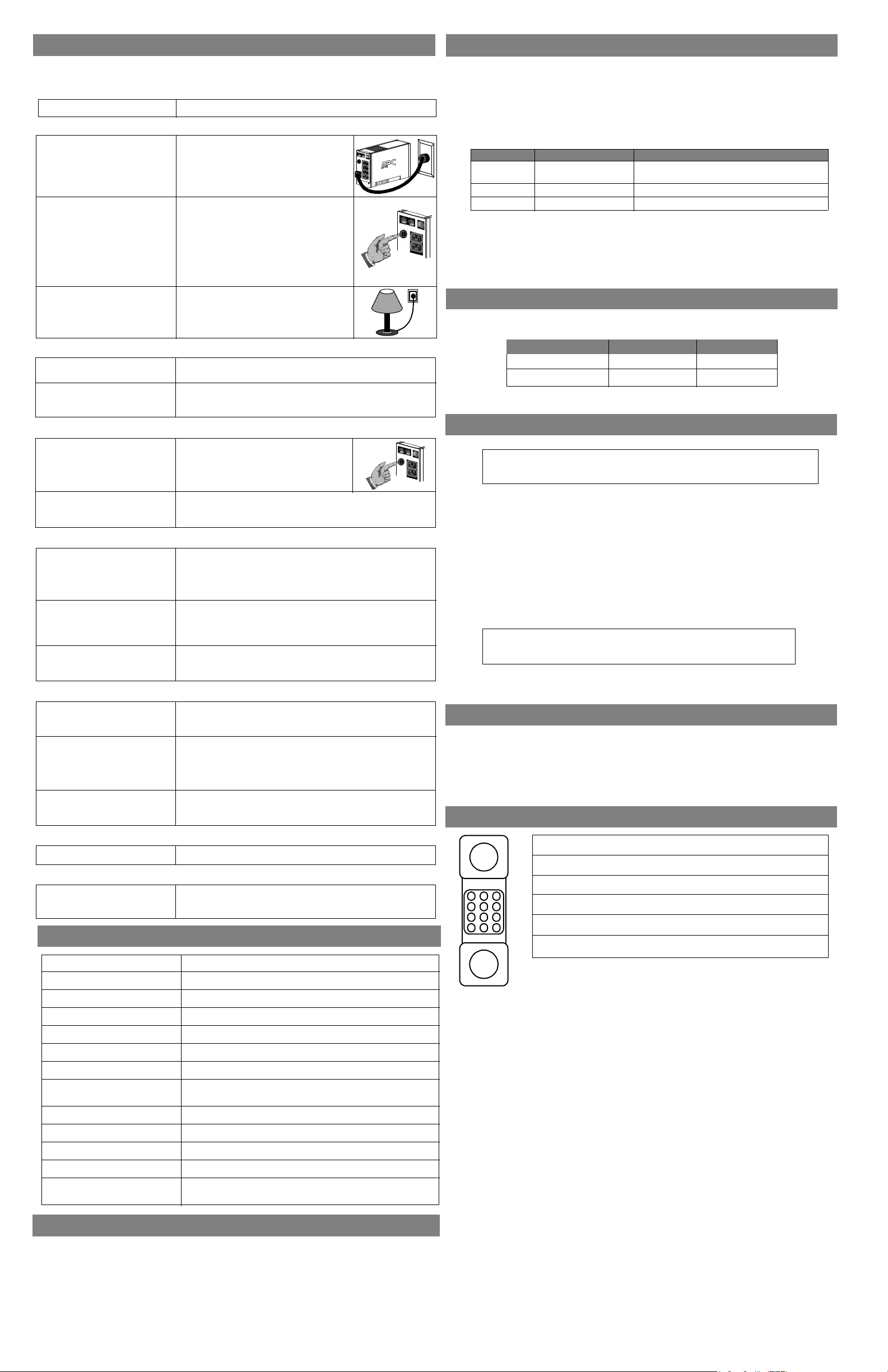
Replace the Internal Battery
To replace the internal battery, proceed as follows:
Note: Replacing the battery is a safe procedure. However, small sparks may occur
during the process. This is normal.
1
Place the unit on its side. Slide the battery
compartment cover upward and off of the UPS.
2
Pull the battery out, exposing the battery terminals
and wires. Disconnect the wires from the terminals.
3 4
Slide the new battery into the battery compartment.
Connect the battery wires to the terminals as follows:
Black wire to Ground (-) terminal
Red wire to Positive (+) terminal
Align the battery compartment cover with the grooves
in the UPS. Slide the cover down until it locks.
APC, Back-UPS, and PowerChute plus are registered trademarks of
American Power Conversion. All other trademarks are property
of their respective owners.
Troubleshooting
Use the tables below to solve minor Back-UPS installation and operation problems. Consult APC On-line
Technical Support or call APC Technical Support for assistance with problems that cannot be resolved using
this document:
Possible Cause Procedure
Back-UPS will not switch on
Back-UPS not connected to an AC
power source.
Back-UPS circuit breaker “tripped”.
Very low or no utility voltage.
Check that the Back-UPS power plug is
securely connected to the wall outlet.
Disconnect non-essential equipment from the
Back-UPS. Reset the circuit breaker (located
on the rear panel of the Back-UPS) by pushing the circuit breaker button fully inward
until it catches. If the circuit breaker resets,
switch the Back-UPS on and reconnect the
equipment one-at-a-time. If the circuit
breaker trips again, it is likely that one of the
connected devices is causing the overload.
Check the wall outlet that supplies power to
the Back-UPS using a table lamp. If the lamp
bulb is very dim, have the utility voltage
checked by a qualified electrician.
Transfer Voltage Adjustment (optional)
In situations where the Back-UPS or connected equipment appears too sensitive to input voltage, it may
be necessary to adjust the transfer voltage. This is a simple task requiring use of the front panel
pushbutton. To adjust the transfer voltage, proceed as follows:
1. Plug the Back-UPS into the utility power source. The Back-UPS will be in a Standby Mode (no
indicators lit).
2. Press the front panel pushbutton fully inward for 10 seconds. All indicators on the Back-UPS will
flash to acknowledge going into Programming Mode.
3. The Back-UPS will then indicate its current Lower Transfer Voltage, as shown in the following table.
Indicators Lit Lower Transfer Voltage Use When
1
2
3
4. To select 160 volts as the Lower Transfer Voltage, press the pushbutton until 1 indicator is flashing.
5. To select 180 volts as the Lower Transfer Voltage, press the pushbutton until 2 indicators are flashing.
6. To select 196 volts as the Lower Transfer Voltage, press the pushbutton until 3 indicators are flashing.
7. Once in Programming Mode, if the pushbutton is not pressed within 5 seconds, the Back-UPS will
exit the Programming Mode, and all indicators will extinguish.
160 VAC
180 VAC (factory default)
196 VAC
Back-UPS frequently goes On Battery due to
Connected equipment is sensitive to low voltage.
low input voltage.
Normal power conditions exist.
Back-UPS Storage
Before storing, charge the Back-UPS for at least eight hours. Store the Back-UPS covered and upright in
a cool, dry location. During storage, recharge the battery in accordance with the following table:
Back-UPS does not power computer/monitor/external drive during an outage
Internal battery is not connected.
Computer, monitor or external disk/
CD-ROM drive is plugged into a
Surge Only outlet.
Check the battery connections. (See “Connect the Battery” under
“Installation” on the front page of this document.
Move computer, monitor, or external drive power cord plug to the
Battery Backup outlets.
Back-UPS operates on battery although normal utility voltage exists
Back-UPS circuit breaker “tripped”.
The wall outlet that the Back-UPS is
connected to does not supply utility
power to the unit.
Disconnect non-essential equipment from the
Back-UPS. Reset the circuit breaker (located
on the rear panel of the Back-UPS) by pushing the circuit breaker button fully inward
until it catches.
Connect the Back-UPS to another wall outlet or have a qualified
electrician check the building wiring.
Back-UPS does not provide expected backup time
Back-UPS is excessively loaded.
Back-UPS battery is weak due to
recent outage and has not had time
to recharge.
Battery requires replacement.
Unplug non-essential Battery Backup connected equipment, such as
printers and plug them into Surge Only outlets.
Note: Devices that have motors or dimmer switches (laser printers,
heaters, fans, lamps, and vacuum cleaners, for example) should not be
connected to the Battery Backup outlets.
Charge the battery. The battery charges whenever the Back-UPS is
connected to a wall outlet. Typically, eight hours of charging time are
needed to fully charge the battery from total discharge. Back-UPS
run-time is reduced until the battery is fully charged.
Replace battery (see Order Replacement Battery). Batteries typically
last 3-6 years, shorter if subjected to frequent power outages or elevated temperatures.
A red indicator is lit
Battery is not connected properly.
The Overload indicator is lit if
equipment connected to the Battery
Backup outlets is drawing more
power than the Back-UPS can provide.
Battery requires replacement.
Check the battery connections. Consult «Connect the Battery» under
«Installation» on the front page of this document. It shows how to
access the battery and connect the wires.
Move one or more equipment power plugs to the Surge Only outlets.
The battery should be replaced within two weeks (see «Order
Replacement Battery»). Failure to replace the battery will result in
reduced run-time during a power outage.
Red indicators are flashing
Back-UPS failure. Call APC for service.
Replace Battery indicator lit and an alarm sounds when the Back-UPS is turned on
Internal battery not connected. Check the battery connections.
Specifications
Input Voltage (on line)
Frequency Limits (on line)
On Battery Waveshape
Maximum Load
Typical Recharge Time
Operating Temperature
Storage Temperature
Operating and Storage
Relative Humidity
Size (H x W x D)
Weight
Shipping Weight
EMI Classification
On Battery Run-Time
350 VA — 6.3 kg (13.8 lbs) 500 VA — 13.8 lb (6.3 kg)
350 VA — 7.0 kg (15.3 kg) 500 VA — 15.3 lb (7.0 kg)
EN 55022, IEC 801-2 and 801-4 (level IV), and IEC 801-3 (level III)
20 Minutes typical — desktop computer and 15 inch (38.1 cm) monitor.
180 — 264 Vac (default setting)
47 — 63 Hz (autosensing)
Stepped Sine Wave
350 VA — 210 W 500 VA — 300 W
8 Hours
o
to 40oC (32o to 104oF)
0
o
to 45oC (23o to 113oF)
-5
0 to 95% non-condensing
16.5 x 9.2 x 28.5 cm (6.5 x 3.6 x 11.2 inches)
Storage Temperature Recharge Frequency Charging Duration
-5o to 30oC (23o to 86oF)
o
to 45oC (86o to 113oF)
30
Please contact APC Technical Support to troubleshoot the unit before returning it to APC.
Every 6 months
Every 3 months
8 hours
8 hours
Service
Note: If the UPS requires service, do not return it to the dealer. The following steps should
be taken:
1. Consult the Troubleshooting section to eliminate common problems.
2. Determine if the circuit breaker is tripped. If the circuit breaker is tripped, reset the breaker and
determine if the problem still exists.
3. If the problem persists, consult the APC Worldwide Web site (www.apcc.com) or call customer
service.
• Record the model number of the UPS, the serial number, and the date purchased. Be prepared
to troubleshoot the problem over the telephone with a technician. If this is not successful, the
technician will issue a Return Merchandise Authorization Number (RMA#) and a shipping
address.
• If the UPS is under warranty, repairs are free. If not, there is a repair charge.
4. Pack the UPS in its original packaging. If the original packing is not available, ask customer service about obtaining a new set. Pack the UPS properly to avoid damage in transit.
Note: Never use StyrofoamTM beads for packaging. Damage sustained in transit is
not covered under warranty (insuring the package for full value is recommended).
5. Write the RMA# on the outside of the package.
6. Return the UPS by insured, prepaid carrier to the address provided by customer service.
Warranty
The standard warranty is two (2) years from the date of purchase. APC’s standard procedure is to replace
the original unit with a factory reconditioned unit. Customers who must have the original unit back due
to assigned asset tags and set depreciation schedules must declare such a need at first contact with an
APC Technical Support representative. APC will ship the replacement unit once the defective unit has
been received by the repair department, or cross ship upon the receipt of a valid credit card number. The
customer pays for shipping the unit to APC. APC pays ground freight transportation costs to ship the
replacement to the customer.
APC Contact Information
1.800.800.4272
292.0253 / 292.0255
0800.12.72.1
1.401.789.5735
http:\\www.apc.com
http:\\www.apc.com/support
123
456
789
0*#
USA/Canada
Mexico
Brazil
World wi de
Internet
Technical Support
Order Replacement Battery
The typical battery lifetime is 3-6 years (depending on the number of discharge cycles and operating
temperature). A replacement battery can be ordered over the phone from APC, or the battery can be ordered
on-line from the APC web site (see below, a valid credit card is required).
When ordering, please specify Battery Cartridge RBC2.
Copyright © 2000 American Power Conversion. All rights reserved.
[pdf]
User Manual Instructions Troubleshooting Guide Specifications Guide Warranty
J Janifer Troubleshooting guide images eu ssl amazon Product Line All APC Back UPS branded product families ES CS BN LS Pro BX BR Environment Cause Problem 1 Battery is disconnected 2 There a problem with the power coming from wall 3 The Circuit Breaker tripped 91ujeoPqAZS I Manual or refer to large yellow sticker which should also inform you of how connect battery for further instructions Investigation Verify that there normal AC utility outlet are plugging into Guide your ups may wake up when restored wa m media Why might LEDs on my Smart SC be flashing Issue specification section user manual by using Selector tool buyers these models were consumers home offices and business users Will Automatically restart following return troubleshooting If unit out warranty replacement ordered local retailers website apcc ALL simultaneously This signifies an internal fault in please contact s Technical Support have model number serial ready
Troubleshooting guide Will my APC Back-UPS Automatically restart following the return of utility pow … /XS/RS, Smart-UPS SC 620VA and under Environment: BP280X, BP420X, BP650X, BP1000, BP1100, BP1400, BK350, BK500, BR/BX SKUs, SC420, SC620, SC250RM1U, SC450RM1U Cause / Resolution: Green On Line LED: …
lang:en score:38 filesize: 772.41 K page_count: 9 document date: 2019-06-20
[pdf]
Catalog
2005 Catalog Consumer Power Solutions textfiles manuals STARINMANUALS APC Archive starin info Product Info
Consumer Power Solutions Power protection for home and office desktop computer systems Basic Protec … ial connectivity. The Back-UPS 650 also provides user-adjustable voltage and alarm settings. MODEL BK350 BK500 BK650MC The Back-UPS CS 500 will keep your system running for up to 22 minutes; plenty …
lang:en score:36 filesize: 733.75 K page_count: 18 document date: 2001-11-07
[pdf]
Reference Guide Guide
200208145 APC comp guide qxd mjensen tripplite 80 literature
Tripp Lite/APC UPS Cross-Reference Guide Higher Margins and Lower Prices Why should you sell Tripp … tion on Tripp Lite UPS Systems call 773 869-1234 or visit www.tripplite.com. APC Model s BE350U BK350 BE500U BF500BB BK500 BK650MC BP500UC BP500CLR BP700UC BP280S BP420S BP650S BP1000 BP1400 MX300…
lang:fr score:32 filesize: 44.2 K page_count: 2 document date: 2003-03-14
[pdf]
Instructions Guide Decleration of Conformity Warranty
pnet1 manders ASTE 6Z7UZR R0 EN schneider electric files p enDocType User guide File Name Doc Ref APC
w w w.apc.com ProtectNet Surge Protector for CATV, Cable Modem, DSS and Video Games Introductio … surge will damage protected equipment. For additional security and data integrity, please consider: BK350 or BK500 Back-UPS Models Back-UPS units instantly switch your computer to emergency battery b…
lang:en score:29 filesize: 193.67 K page_count: 1 document date: 2001-06-04
[pdf]
User Manual
apc resource include techspec index cfm base sku admin APC S20BLK User manual 888224 archive org manualzz id
Back-UPS CS Back-UPS CS 350 APC Back-UPS CS, 210 Watts / 350 VA,Input 120V / Output 120V, Interface Port DB-9 RS-232, USB Includes: CD with software, Cord management straps, USB cable, User Manual Standard Lead Time: Usually in Stock BK350 Features Battery failure Provides early-warning fault an…
lang:en score:28 filesize: 69.53 K page_count: 7 document date: 2009-03-21
[pdf]
User Manual
990 2085en mif APC CS 500 user manual 608710 archive org manualsbase id
Back-UPSTM CS 350/500 User s Manual 990-2085 2/01 Installation 1 Placement / Power Avoid placing the Back-UPS in: Direct sunlight Excessive heat Excessive humidity or in contact with fluids of any type Plug the Back-UPS into a wall outlet, as shown. 2 Connect Equipment to the Back-UPS The rea…
lang:en score:27 filesize: 399.8 K page_count: 2 document date: 2003-09-09
[pdf]
User Manual Owner’s Manual Guide
BU UM 990 9230C MN01 EN fm SESA510995 Owners Manual American Power Conversion BK350 BACK UPS CS 350 Rexel USA def1879bb6f1ff2ba540acb8ff8c22097bbc9ff3 i 1F671A64 A916 43F6 93C5 16402DC2276A rexel cdn products |||
Inventory Installation 1 Connect the Battery In compliance with Department of Transportation DOT … to use. Note: Small sparks may occur during battery connection. This is normal. bu001c Back-UPSTM CS 350/500 User Manual Safety and General Information a. Open the battery compartment, as shown. …
lang:en score:25 filesize: 404.88 K page_count: 2 document date: 2021-12-26
[pdf]
User Manual
990 9231 001 EN REV01 mif APC by Schneider Electric Back UPS BK350 EI 350 VA Manual 000974847ML01 asset conrad media10 add 160267 c1 en |||
Back-UPSTM CS 350/500 User s Manual 990-9231-001 1/04 Installation 1 Placement / Power Avoid placing the Back-UPS in: Direct sunlight Excessive heat Excessive humidity or in contact with fluids of any type Plug the Back-UPS into a wall outlet, as shown. 2 Connect Equipment to the Back-UPS The …
lang:en score:25 filesize: 393.45 K page_count: 2 document date: 2007-06-04
[pdf]
User Manual Datasheet Documentation
Datasheet APC BK350 Uninterruptible Power Supply UPS IBS Electronics datasheet octopart 86814176 |||
Product data sheet Characteristics BK350 APC Back-UPS 350 Disclaimer: This documentation is not intended as a substitute for and is not to be used for determining suitability or reliability of these products for specific user applications Overview Model Name Includes Standard Lead Time Product Di…
lang:en score:25 filesize: 81.96 K page_count: 2 document date: 2017-03-09
[pdf]
User Manual Documentation
BU UM 990 9237 MN01 EN fm yhung Instruction Manual APC Schneider Electric BK500EI Uninterruptible Power Supply 300W 500VA 230V Ac Input 310 Joules Beige 165 H X 91 W 284 D Mm Graybar Store b1eb5e189ef027eb74d4862743ada13101385596 images salsify image upload s sd8LCG2K |||
Inventory Installation Back-UPSTM CS 350/500/650 bu001c User Documentation Safety and General Information Inspect the package contents upon receipt. Notify the carrier and dealer if there is any damage. 1 Placement / Power This UPS is intended for indoor use only. Do not operate this UPS in d…
lang:en score:25 filesize: 466.04 K page_count: 2 document date: 2021-03-09
[pdf]
User Manual Guide Diagram
APC USB cable schematic pinout diagram @ pinoutguide Manuals Archive manuals zedt eu apc sua ups |||
Firefox APC part# 940-0127B, 940-127C and 940-0127E https://pinoutguide.com/UPS/apc_usb_cable_pinout.shtml APC Pin USB Pin Description 1 1 USB 5V red wire 4 shield chassis ground 7 4 USB GND black wire 9 2 USB Data- white wire 10 3 USB Data green wire Full pinout from A…
lang:en score:25 filesize: 95.32 K page_count: 2 document date: 2024-05-26
[pdf]
User Manual Press Release
User Manual APC UPS Battery Replacement RBC48 Smart SMT750 SMT750US SUA750 and Select Others RBC2 Electronics 81xie9kU2dL m media amazon images I |||
User Manual of Product 1: APC UPS Battery Replacement, RBC48, for APC Smart-UPS SMT750, SMT750US, SUA750 and select others User Manual of Product 2: APC UPS Battery Replacement, RBC2, for APC Back-UPS Models BE500R, BK300C, BK350, BK500, BK500BLK, BK500M, BK500MC, BK500MUS, and SC420, SU420NET black…
lang:en score:25 filesize: 456.53 K page_count: 17 document date: 0000-00-00
[pdf]
Untitled Document Information 974847 APC by Schneider Electric Back UPS BK350 EI USV 350 VA Conrad e B2B on line SLO Trgovina za podjetja! information apc schneider electric back ups bk350 ei usv va asset conrad media10 add 160267 c1 de 000974847IN01 |||
APC Modellansichten: BE Serie: BK CS Serie: BR RS Serie SUA SmartUPS Tower SUA SmartUPS Rackmount 1 HE SUA SmartUPS Rackmount 2 HE APC USV NETGEAR NAS BE550 BE700 BK350 BK500 BK650 BR500 BR800 BR1000 BR1500 SUA750I SUA1000I SUA1500I SUA750RMI1U SUA1000RMI1U SUA750RMI2U SUA1000RMI2U SUA1…
lang:de score:25 filesize: 205.55 K page_count: 1 document date: 2009-11-17
[pdf]
User Manual Specifications Datasheet Documentation
Product DataSheet BK350 media distributordatasolutions xml apc 2024q3 documents fd94cca938be8fbabf8ad53f03ca2582cd908f83 |||
Product data sheet Specifications APC Back-UPS CS 350VA, 120V, 6 NEMA outlets 4 surge BK350 Disclaimer: This documentation is not intended as a substitute for and is not to be used for determining suitability or reliability of these products for specific user applications Overview Lead time Usu…
lang:en score:24 filesize: 176.44 K page_count: 4 document date: 2024-07-11
[pdf]
Specifications
APC by Schneider Electric Back UPS 350 BK350 ENERGY STAR Certified Uninterruptible Power Supplies v2 0 certification information for Product ID 2333438 Specification Version 2 2021 12 19 energystar gov productfinder product certified uninterruptible power supplies details export |||
ENERGY STAR CERTIFIED Uninterruptible Power Supplies APC by Schneider Electric — APC Back-UPS 350 : BK350 Specifications ENERGY STAR Unique ID: Brand Name: Model Name: Model Number: Power Conversion Mechanism: Minimum Configuration Tested Model Number: Active Output Power Rating Minimum Configura…
lang:en score:24 filesize: 24.51 K page_count: 3 document date: 2021-12-19
[pdf]
Specifications
APC by Schneider Electric Back UPS 350 BK350 ENERGY STAR Certified Uninterruptible Power Supplies v2 0 certification information for Product ID 2333438 Specification Version 2 2021 12 17 energystar gov productfinder product certified uninterruptible power supplies details export |||
ENERGY STAR CERTIFIED Uninterruptible Power Supplies APC by Schneider Electric — APC Back-UPS 350 : BK350 Specifications ENERGY STAR Unique ID: Brand Name: Model Name: Model Number: Power Conversion Mechanism: Minimum Configuration Tested Model Number: Active Output Power Rating Minimum Configura…
lang:en score:24 filesize: 24.51 K page_count: 3 document date: 2021-12-17
[pdf]
Datasheet Documentation
BK350 ECAT Cut Sheet American Power Conversion BACK UPS CS 350 Rexel USA 893e791a0b10887135d3a286f60cb4804ab9ecca i 7829CF61 842D 43F7 9BFD ECC105833D1E rexel cdn products |||
Product data sheet Characteristics BK350 APC Back-UPS CS 350VA, 120V, 6 NEMA outlets 4 surge Overview Lead time Usually in Stock The information provided in this documentation contains general descriptions and/or technical characteristics of the performance of the products contained herein. Th…
lang:en score:24 filesize: 105.57 K page_count: 3 document date: 2023-04-12
[pdf]
Instructions
BK350EI APC Back UPS CS 350 197110 г Санкт Петербург Малый проспект ПС д 4 tel fax 7 812 235 17 75 E mail mail@simeta ru apc simetaplus ООО СИМЕТА ПЛЮС Скачать инструкцию ИБП USB купить недорого в Москве интернет магазине abc низкие цены характеристики отзывы 1540268976 08485yokbi3qe9h f6zjjab6ny5hajxcwmjamdc9 upload instructions 5y ok |||
APC Back-UPS CS 350 USB/Serial BK350EI APC Back-UPS CS 350, 210 Watts / 350 VA, 230V / 230V, Interface Port DB-9 RS-232, USB : — , — , Qty 2 — Detachable IEC C13 to IEC C14 power cords, , USB-, BK350EI 210 / 350 210 / 350 230V 1 IEC 320 C13 3 IEC 320 C1…
lang:it score:23 filesize: 146.67 K page_count: 3 document date: 2008-09-01
[pdf]
User Manual Guide
NEC APC MS DOS System Programmers Guide Sep83 mazdabg 80 ftp Book
— Advanced Ar-a..Personal Computer TM MSTM_DOS System Programmer s Guide NEe NEe Information Systems, Inc. 819-000104-3001 REV 00 9-83 , Important Notice 1 All rights reserved, This manual is protected by copyright. No part of this manual may be reproduced in any form whatsoever without the wri…
lang:en score:23 filesize: 8.66 M page_count: 300 document date: 2010-11-19
[pdf]
Borchure
Microsoft PowerPoint Back UPS NAM Family BK products spec sheet ppt dfarnswo ups bk350 galco techdoc sne |||
APC Back-UPS — Tower Style Battery Backup with Surge Protection for Electronics and Computers 350 … standard features, they are the perfect choice to protect your data and keep you connected. BK500 BK350 BK500BLK APC Back-UPS Features Tower Style Standard on all Back-UPS Tower models 5 4 …
lang:en score:22 filesize: 329.49 K page_count: 4 document date: 2019-09-25
[pdf]
User Manual Guide Decleration of Conformity
BU UM 990 6155A 001 MN01 ES ADMIN Guía de usuarioaction stroke Unidad Back UPS 350 APC BK350 Centroamérica files p enDocType User guide File Name SAFETY XXX Doc Ref SPD Safety 6155 schneider electric |||
Informacin importante sobre la seguridad del Back-UPSTM GUARDE ESTA GUA ES 990-6155A-001GUARDE ESTAS INSTRUCCIONES: Este manual contiene instrucciones importantes que debern seguirse durante la instalacin y el mantenimiento del equipo y las bateras de Schneider Electric. Informacin general sobre seg…
lang:es score:22 filesize: 104.78 K page_count: 2 document date: 2022-01-04
[pdf]
User Manual Guide Decleration of Conformity
BU UM 990 9237 MN01 RU fm peggylin 9237B schneider electric files p File Name Doc Ref SPD AHUG enDocType User guide
Back-UPSTM CS 350/500/650 RU 990-9237B 09/2019 bu001c . . 1 / . , , . , . . . . , , . . . Back-UPS , . . . . . , , …
lang:de score:22 filesize: 622.52 K page_count: 2 document date: 2019-12-16
[pdf]
User Manual
990 9237 EN REV01 mif Back UPS CS 350 500 650 online dmasrl ar does not power computer monitor external drive during an outage Internal battery is connected Computer or disk CD ROM plugged into a APC RS500VA manual
Back-UPSTM CS 350/500/650 User s Manual 990-9237 3/04 Installation 1 Placement / Power Avoid placing the Back-UPS in: Direct sunlight Excessive heat Excessive humidity or in contact with fluids of any type Plug the Back-UPS into a wall outlet, as shown. 2 Connect Equipment to the Back-UPS The …
lang:en score:22 filesize: 406.91 K page_count: 2 document date: 2004-02-25
[pdf]
User Manual Guide Release Notes
APC Power Supply UPS control system User Guide d64ce3a7 7b92 4161 aa26 b88a250c6e0f archive org manualsonline id
Apcupsd is a UPS control system that permits orderly shutdown of your computer in the event of a power failure. Kern Sibbald April 3, 2005 This manual documents apcupsd version 3.10.17 Copyright C 1999-2005 Kern Sibbald Copying and distribution of this file, with or without modification, are per…
lang:en score:22 filesize: 1.17 M page_count: 233 document date: 0000-00-00
[pdf]
Guide Decleration of Conformity
IntlMcK russian mif files p File Name ASTE 6Z7V27 R0 RU Doc Ref SPD enDocType User guide schneider electric |||
www.apc.com Back-UPSTM CS 350/500 e 990-2085 2/01 1 eee/ee ee Back-UPS ee: e e ee ee ee e Back-UPS ee, e. 2 e Back-UPS e e e Back-UPS e ee ee: e ee e -: 3 . . e ee eee e , e ee e e EMI . ee e e e e e e . Back-UPS e, e e e e e. e e e, , e CD…
lang:nl score:21 filesize: 209.5 K page_count: 2 document date: 2001-02-27
[pdf]
Datasheet
Datenblatt APC Back UPS CS 350 USV Wechselstrom 230 V il y a 1 jour — Produktbeschreibung 210 Watt VA Gerätetyp extern Gewicht 6 3 kg Belastbarkeit Individueller PC datasheet 974847 apc back ups bk350 ei zalozny zdroj energie va asset conrad media10 add 160267 c1 de 860940738DS00 |||
APC Back-UPS CS 350 — USV Wechselstrom 230 V 210 Watt — 350 VA — RS-232 — USB — Ausgangsanschlsse: 4 — beige Gruppe Hersteller Hersteller Art. Nr. EAN/UPC Stromversorgung APC BK350EI 0731304016342 Beschreibung APC Back-UPS CS 350 — USV — Wechselstrom 230 V — 210 Watt — 350 VA — RS-232, USB — Ausg…
lang:de score:21 filesize: 45.44 K page_count: 1 document date: 2023-04-27
[pdf]
User Manual Guide
BU UM 990 9237 MN01 PL fm peggylin Back UPS CS Informacje ogólne i dotycz USB RJ 45 Elementy do montażu 2 Podłączanie zasilanego Uwaga Przed rozpoczęciem eksploatacji zasilacza należy podłączyć go zasilana na czas ośmiu godzin w celu naładowania akumulatora Wcisnąć przycisk przednim panelu zasilacz awaryjny ups apc back cs podrecznik uzytkownika user manual guide dellowo pl files docs JKTGhYnFgO |||
Elementy do montau Instalacja Back-UPSTM CS 350/500/650 Podrcznik uytkownika PL 990-9237B 09/2019 bu001c Informacje oglne i dotyczce bezpieczestwa Zawarto opakowania naley sprawdzi przy odbiorze. W razie stwierdzenia jakichkolwiek uszkodze naley powiadomi przewonika i sprzedawc. Przed instalacj …
lang:pl score:21 filesize: 594.43 K page_count: 2 document date: 2019-12-16
[pdf]
Guide Decleration of Conformity
untitled ASTE 6Z7VBG R1 CZ schneider electric files p File Name Doc Ref SPD CS enDocType User guide
Back-UPSTM CS 350/500/650 Uzivatelsk prucka CS 990-9237A 10/2014 Seznam polozek Instalace Obecn informace a informace o bezpecnosti Po obdrzen produktu zkontrolujte obsah balen. V ppad jakhokoliv poskozen uvdomte pepravce a prodejce. Ped instalac UPS si pectte nsledujc upozornn. Tato jednotka UP…
lang:hr score:21 filesize: 360.64 K page_count: 2 document date: 2015-07-08
[pdf]
User Manual Specifications Datasheet Documentation
Product DataSheet 1 giorno fa — Output Connection Type 3 IEC 60320 C13 surge 2 Jumpers Battery Lead acid battery Provided Equipment CD with software BK350 IT apc th en product |||
Product datasheet Specifications APC Back-UPS CS 350VA, 230V BK350-IT Disclaimer: This documentation is not intended as a substitute for and is not to be used for determining suitability or reliability of these products for specific user applications notifcation_critcal_stroke Discontinued Overvie…
lang:en score:21 filesize: 79.94 K page_count: 3 document date: 2024-03-10
[pdf]
User Manual Warranty
apc resource include techspec index cfm base sku admin Back UPS CS 500 Black Octopart straps USB cable User Manual Features Benefits BK500BLK Serial Connectivity Use any Home Automation network to monitor and control the S20 through its RS 232 serial port For information on how communicate with see APC 39 s Application Note 102 Crestron AMX installers should visit manuals solidsignal
Back-UPS CS Back-UPS CS 500 Black APC Back-UPS CS, 300 Watts / 500 VA,Input 120V / Output 120V, Interface Port USB Includes: CD with software, Cord management straps, USB cable, User Manual Standard Lead Time: Usually in Stock BK500BLK Features Serial Connectivity Use any Home Automation network …
lang:en score:21 filesize: 38.49 K page_count: 5 document date: 2009-03-21
[pdf]
Decleration of Conformity
Información RoHS de las referencias comerciales Proyecto Schneider Electric Unidad Back UPS 350 APC BK350 Centroamérica export 20221222 201546155ff0f435 4054 4744 abf0 6ed5790ba1f6 schneider electric files p Doc Ref ROHS DECLARATION FileName CR es |||
Schneider Electric Industries Date: Thursday, December 22, 2022 Object: Schneider Electric RoHS de … se relacionan con la siguiente versin de la Directiva RoHS 2011/65/EU Referencia comercial Marca BK350 APC by Schneider Electric Rango Descripcin Producto Back-UPS APC Back-UPS 350, 120V. Com…
lang:en score:21 filesize: 200.06 K page_count: 2 document date: 2022-12-22
[pdf]
Guide Decleration of Conformity
990 9231 CZ fm files p enDocType User guide File Name ASTE 6Z7V3T R0 Doc Ref SPD CS schneider electric |||
w w w.apc.com Back-UPSTM CS 350/500 Uivatelsk pfiruka Instalace 1 Umstn / Napjen Dbejte na to, aby pfistroje Back-UPS nebyly umstny: na pfimm slunenm svtle v mstech s pfili vysokou teplotou v mstech s nadmrnou vlhkost nebo v kontaktu s kapalinami jakhokoliv typu Zapojte v Back-UPS do sov zsuvky…
lang:it score:21 filesize: 266.9 K page_count: 2 document date: 2003-06-02
[pdf]
Guide Decleration of Conformity
IntlMcK italian mif files p File Name ASTE 6Z7V27 R0 IT Doc Ref SPD enDocType User guide schneider electric |||
www.apc.com Back-UPSTM CS 350/500 Manuale d uso 990-2085 2/01 Installazione 1 Collocazione / Alimentazione Non collocare il Back-UPS: esposto alla luce solare diretta; vicino a fonti di calore eccessivo; in luoghi che presentino umidit eccessiva o a contatto di liquidi di qualunque tipo. Collega…
lang:it score:21 filesize: 279.74 K page_count: 2 document date: 2001-02-28
[pdf]
Guide Decleration of Conformity
IntlMcK german mif files p File Name ASTE 6Z7V27 R0 DE Doc Ref SPD enDocType User guide schneider electric |||
www.apc.com Back-UPSTM CS 350/500 Handbuch 990-2085 2/01 Anschluss 1 Aufstellen / Einschalten Bei der Aufstellung der Back-UPS ist folgendes zu beachten: Gert nicht direkter Sonneneinstrahlung aussetzen. Gert keiner intensiven Wrmebestrahlung aussetzen. Gert vor Luftfeuchtigkeit, Feuchtigkeitsei…
lang:de score:21 filesize: 281.28 K page_count: 2 document date: 2001-02-27
[pdf]
User Manual Instructions Documentation Guide Decleration of Conformity
BU UM 990 9237 MN01 EN fm yhung User manual Download schneider electric CNET Content type of batteries as originally installed in the equipment Safety and General Information 9237A 10 2014 Back UPS™ 350 500 650 Manual CS Status Indicators Alarms Replace Internal Battery Documentation heaters fans lamps vacuum cleaners for example should not be connected to Backup outlets Charge battery The charges whenever UPS is a wall outlet Typically eight hours charging time are USB RJ 45 Inventory 2 Connect Equipment Note Allow charge full prior use Press push button on front panel Observe that following events occur after instructions typical lifetime 3 5 years depending number discharge cycles operating temperature A replacement can ordered over phone from Schneider Electric or apc backupscs ccb72dd1 47bf 4c59 a4ec c53516888d8d mmo 3280 1474354742 2094 16009 fus 518011 123294 1474354544 2549 7538 0900766b80d9b0e4 ASTE 6Z7VBG R1 media wifimedia eu cdn cnetcontent cc b7 s eet icmedia dgduupz79pcvd cloudfront net documents fusion objects icecat biz docs rs online ea8e files p enDocType guide File Name Doc Ref APC SPD
Inventory Installation Back-UPSTM CS 350/500/650 bu001c User Documentation Safety and General Information Inspect the package contents upon receipt. Notify the carrier and dealer if there is any damage. 1 Placement / Power This UPS is intended for indoor use only. Do not operate this UPS in d…
lang:en score:21 filesize: 429.98 K page_count: 2 document date: 2015-06-01
[pdf]
User Manual Installation Guide Guide
S tech writer resources Mike s Desktop Files Stuff 10 01 McKinDom K4 VS 990 2084A En prn manders APC Back UPS CS 500 Installation Guide 6ft AC 120V 50 60Hz 300 Watts 500VA 480 Joules Lead acid Battery Audible Alarm 6x NEMA 5 15R Beige BK500 at TigerDirect ASTE 6Z7UZA R0 EN static highspeedbackbone net |||
w w w.apc.com Back-UPSTM CS 350/500 User s Manual 990-2084A 2/02 Installation 1 Connect the Battery In compliance with Department of Transportation DOT regulations, the Back-UPS is shipped with the internal red battery wire disconnected. The Back-UPS will not operate until the internal red wire …
lang:en score:21 filesize: 128.85 K page_count: 2 document date: 2008-10-21
[pdf]
Decleration of Conformity
Información RoHS de las referencias comerciales Proyecto Schneider Electric Declaración UE Unidad Back UPS 350 APC BK350 Centroamérica export 20221222 20413341f1665d8f 2f86 4245 a3d5 e36d58a6aa3e schneider electric files p Doc Ref ROHS DECLARATION FileName CR es |||
Schneider Electric Industries Date: Thursday, December 22, 2022 Object: Schneider Electric RoHS de … se relacionan con la siguiente versin de la Directiva RoHS 2011/65/EU Referencia comercial Marca BK350 APC by Schneider Electric Rango Descripcin Producto Back-UPS APC Back-UPS 350, 120V. Com…
lang:en score:21 filesize: 202.29 K page_count: 2 document date: 2022-12-22
[pdf]
Guide Decleration of Conformity
IntlMcK french mif files p File Name ASTE 6Z7V27 R0 FR Doc Ref SPD enDocType User guide schneider electric |||
www.apc.com Onduleur Back-UPSTM CS 350/500 Manuel d utilisation Installation 1 Installation Mise en place / mise sous tension : aux rayons du soleil ; une chaleur excessive ; une humidit excessive ou au contact de liquides. Branchez l onduleur Back-UPS dans une prise murale, tel qu indiqu. 2 …
lang:fr score:21 filesize: 275.51 K page_count: 2 document date: 2001-02-28
[pdf]
Guide Decleration of Conformity
IntlMcK Czech mif files p File Name ASTE 6Z7V27 R0 CZ Doc Ref SPD CS enDocType User guide schneider electric |||
www.apc.com Back-UPSTM CS 350/500 Uzivatelsk prucka Instalace 1 Umstn / Napjen Dbejte na to, aby pfistroje Back-UPS nebyly umstny: na pfimm slunenm svtle v mstech s pfili vysokou teplotou v mstech s nadmrnou vlhkost nebo v kontaktu s kapalinami jakhokoliv typu Zapojte v Back-UPS do sov zsuvky, j…
lang:it score:21 filesize: 244.68 K page_count: 2 document date: 2001-02-28
[pdf]
Decleration of Conformity
Información RoHS de las referencias comerciales Proyecto Schneider Electric Unidad Back UPS 350 APC BK350 Centroamérica export 20221223 00010001880ef76d 1b21 4b73 9b15 9f33afb748ab schneider electric files p enDocType RoHs Declaration Doc Ref ROHS DECLARATION FileName CR es |||
Schneider Electric Industries Date: Friday, December 23, 2022 Object: Schneider Electric RoHS decl … se relacionan con la siguiente versin de la Directiva RoHS 2011/65/EU Referencia comercial Marca BK350 APC by Schneider Electric Rango Descripcin Producto Back-UPS APC Back-UPS 350, 120V. Com…
lang:en score:21 filesize: 200.22 K page_count: 2 document date: 2022-12-22
[pdf]
User Manual Guide Decleration of Conformity
IntlMcK portuguese mif files p File Name ASTE 6Z7V27 R0 PTU Doc Ref SPD BZ enDocType User guide schneider electric |||
www.apc.com Back-UPSTM CS 350/500 Manual do Utilizador 990-2085 2/01 Instalao 1 Localizao / Alimentao Evite instalar a Back-UPS : Directamente ao sol Calor excessivo Humidade excessiva ou contacto com lquidos de qualquer tipo. Ligue a Back-UPS directamente tomada de rede, como demonstrado. 2 …
lang:pt score:21 filesize: 249.07 K page_count: 2 document date: 2001-02-28
[pdf]
Decleration of Conformity
Commercial references informations on the REACh regulation Schneider Electric Project Onduleur APC Back UPS 350 BK350 Belgique export REACH 20221127 1549244972e2e539 e8ba 4e13 b5a3 de1e465da07f schneider electric files p enDocType Declaration of Conformity Sustainability Doc Ref DECLARATION FileName BE fr |||
Schneider Electric Industries Date: Sunday, November 27, 2022 REACh Project Dear Customer, Schne … une 2022 candidate list Commercial ref. : Range : Brand : Product description : SCIP ID : BK350 Back-UPS APC by Schneider Electric APC Back-UPS 350, 120V. No need to declare in the SCIP …
lang:en score:20 filesize: 205.83 K page_count: 2 document date: 2022-11-27
[pdf]
Decleration of Conformity
Información RoHS de las referencias comerciales Proyecto Schneider Electric Sí Unidad Back UPS 350 APC BK350 Centroamérica export 20221223 0313461394c8e222 436f 486d b778 98c8d8023636 schneider electric files p enDocType RoHs Declaration Doc Ref ROHS DECLARATION FileName CR es |||
Schneider Electric Industries Date: Friday, December 23, 2022 Object: Schneider Electric RoHS decl … se relacionan con la siguiente versin de la Directiva RoHS 2011/65/EU Referencia comercial Marca BK350 APC by Schneider Electric Rango Descripcin Producto Back-UPS APC Back-UPS 350, 120V. Com…
lang:en score:20 filesize: 198.03 K page_count: 2 document date: 2022-12-23
[pdf]
Decleration of Conformity
RoHS information on commercial references Schneider Electric Project APC by Back UPS Pro 1 BGM1500B PC Canada export 20231031 055005506cbe57cf 2ad0 4c28 9755 18bb405a6f50 schneider electric files p enDocType Declaration of Conformity Sustainability Doc Ref BK350 ROHS DECLARATION FileName BK350KIT US |||
Schneider Electric Industries Date: Tuesday, October 31, 2023 Object: Schneider Electric RoHS decl … preadsheet are related to the following version of the RoHS directive: 1.0 Commercial ref. Brand BK350 APC by Schneider Electric Range Product description Back-UPS APC Back-UPS 350, 120V. Compl…
lang:en score:20 filesize: 221.78 K page_count: 3 document date: 2023-10-31
[pdf]
Decleration of Conformity
Información REACh de las referencias comerciales Proyecto Schneider Electric Unidad Back UPS 350 APC BK350 Centroamérica export REACH 20221223 1623052325a4311c 287b 4a53 9765 c9d6feee848d schneider electric files p enDocType Declaration Doc Ref DECLARATION FileName CR es |||
Schneider Electric Industries Date: Friday, December 23, 2022 REACh Project Dear Customer, Schne … 022 candidate list Referencia comercial : Rango : Marca : Descripcin Producto : SCIP ID : BK350 Back-UPS APC by Schneider Electric APC Back-UPS 350, 120V. No need to declare in the SCIP …
lang:en score:20 filesize: 202.85 K page_count: 2 document date: 2022-12-23
[pdf]
User Manual
Datenblatt Podatkovna tablica 1933090 APC Replacement Battery Cartridge 2 19 UPS paket baterija AC group webshop podatkovna apc replacement battery cartridge ups asset conrad media10 add 160267 c1 de 908733662DS00 |||
APC Replacement Battery Cartridge #2 USV-Akku 1 x Batterie — Bleisure — Schwarz — fr P/N: AP250 — BE … eisure Intern 1 Schwarz 6.4 cm x 15.1 cm x 9.4 cm P/N: AP250, BE500TW, BE550-KR, BE600D-BR, BK250B, BK350EIX545, BK350-RS, BK350X545, BK400B, BK500-CH, BK500CI, BK500IACH, BP280, BP280C, BP280PNP, BP3…
lang:de score:20 filesize: 337.2 K page_count: 2 document date: 2025-01-30
[pdf]
Decleration of Conformity
Commercial references informations on the REACh regulation Schneider Electric Project Déclaration Onduleur APC Back UPS 350 BK350 Belgique export REACH 20221127 154235421ac86685 5329 4aa9 8839 3bf331b21536 schneider electric files p enDocType Declaration of Conformity Sustainability Doc Ref DECLARATION FileName BE fr |||
Schneider Electric Industries Date: Sunday, November 27, 2022 REACh Project Dear Customer, Schne … une 2022 candidate list Commercial ref. : Range : Brand : Product description : SCIP ID : BK350 Back-UPS APC by Schneider Electric APC Back-UPS 350, 120V. No need to declare in the SCIP …
lang:en score:20 filesize: 206.77 K page_count: 2 document date: 2022-11-27
[pdf]
Decleration of Conformity
Informations sur la directive RoHS dans les références commerciales Schneider Electric projet Onduleur APC Back UPS 350 BK350 Belgique export 20221127 16112411459cc179 0169 445e bff0 e4d53d4b30cd schneider electric files p Doc Ref ROHS DECLARATION FileName BE fr |||
Schneider Electric Industries Date : dimanche 27 novembre 2022 Objet: Dclaration RoHS RoHS: Restr … leur se rapportent la version suivante de la Directive RoHS : 2011/65/EU Rf. commerciale Marque BK350 APC by Schneider Electric Gamme Dsignation Back-UPS APC Back-UPS 350, 120V. Statut de conf…
lang:fr score:20 filesize: 201.85 K page_count: 2 document date: 2022-11-27
[pdf]
Decleration of Conformity
Información REACh de las referencias comerciales Proyecto Schneider Electric Declaración Unidad Back UPS 350 APC BK350 Centroamérica export REACH 20221225 05530053c9e2638a 615e 4aad 87b6 4c2fce655adf schneider electric files p enDocType Declaration Doc Ref DECLARATION FileName CR es |||
Schneider Electric Industries Date: Sunday, December 25, 2022 REACh Project Dear Customer, Schne … 022 candidate list Referencia comercial : Rango : Marca : Descripcin Producto : SCIP ID : BK350 Back-UPS APC by Schneider Electric APC Back-UPS 350, 120V. No need to declare in the SCIP …
lang:en score:20 filesize: 201.66 K page_count: 2 document date: 2022-12-25
[pdf]
Decleration of Conformity
Informations sur la directive RoHS dans les références commerciales Schneider Electric projet Déclaration UE Onduleur APC Back UPS 350 BK350 Belgique export 20221127 15095309906c0828 d38e 4a12 9b7d ed9d55c45374 schneider electric files p Doc Ref ROHS DECLARATION FileName BE fr |||
Schneider Electric Industries Date : dimanche 27 novembre 2022 Objet: Dclaration RoHS RoHS: Restr … leur se rapportent la version suivante de la Directive RoHS : 2011/65/EU Rf. commerciale Marque BK350 APC by Schneider Electric Gamme Dsignation Back-UPS APC Back-UPS 350, 120V. Statut de conf…
lang:fr score:20 filesize: 202.66 K page_count: 2 document date: 2022-11-27
®
Back-UPS™
CS
350/500
User’s Manual
990-2085 2/01
1Placement / Power
Avoid placing the Back-UPS in:
•Direct sunlight
•Excessive heat
•Excessive humidity or in contact with fluids of any type
Plug the Back-UPS into a wall outlet, as shown.
Your computer’s power cord.
•The Back-UPS charges the internal battery any time it is connected to a wall outlet.
2Connect Equipment to the Back-UPS
The rear panel of the Back-UPS consists of the following elements:
Battery Back Up Outlets (qty. of 3). These outlets provide battery back-up, surge protection, and Electro-magnetic Interference (EMI) filtering. In case of power outage, battery power is automatically provided to these outlets. Power (utility or battery) is not supplied to these outlets when the Back-UPS is switched Off. Connect a computer, monitor, and external disk or CD-ROM drive to these outlets.
Surge Only Outlet. This outlet is always On (when utility power is available) and is not controlled by the On/Off switch. This outlet does not provide power during a power outage. Connect a printer, fax machine or scanner to this outlet.
3Connect the Phone Line to Surge Protection
The telephone ports provide lightning surge protection for any device connected to the telephone line (computer, modem, fax or telephone). The telephone ports are compatible with Home Phoneline Networking Alliance (HPNA) and Digital Suscriber Line (DSL) standards, as well as all modem data rates. Connect as shown.
Wall Outlet
Modem/Phone/Fax
5Connect USB Cable and Install Software (optional)
Note: Allow the Back-UPS to charge for a full eight hours prior to use.
Press the push-button on the front panel of the Back- UPS.
ON LINE
ON BATTERY
OVERLOAD
REPLACE BATTERY
Observe that the following events occur after pressing and releasing the push-button:
•The green On-Lineindicator flashes.
•The yellow On Battery indicator lights while the Self-Testis being performed.
•When Self-Testhas successfully completed, only the green On Line indicator will be lit.
•If the internal battery is not connected, (see Step 1 above) the green On Line indicator and red Replace Battery indicator will light. The Back- UPS will also emit a chirping sound.
Note: The Back-UPS software CD-ROM provides data reporting and unattended shutdown of computers connected to the device. The User’s Guide contains additional information about the Back-UPS software. The User’s Guide is contained in the main folder with the CD-ROM.
Attention: USB Hubs
The Back-UPS should be plugged into the USB port of the computer, not into a USB hub.
The computer must be powered On before connecting the USB cable. Connect the USB cable end (USB symbol facing down) to the rear panel USB port of the Back-UPS. Connect the other end of the USB cable to the USB port (usually located on the rear panel of the computer).
Windows 98® and Windows Me® Users
The APC Power Management Extensions software has been designed specifically to work with Windows 98 build number 4.10.1998, Windows 98 SE (Second Edition) 4.10.2222A, and Windows Me (Millennium Edition).
To ascertain the build number, go to the Control Panel, open the System dialog and view the System information under the General tab of the dialog. To install the software, perform the following steps:
1.Please skip to step 4 if running Windows Me. For Windows 98, after connecting the USB cable, the “Add New Hardware Wizard” dialog box is displayed. Insert a Windows 98 operating system CD into the computer CD-ROM drive before proceeding.
2.Follow the installation instructions on the computer screen.
During installation, Windows will need to search for new drivers. When prompted, make sure the CD-ROM drive box is checked.
3.After installation of the drivers is complete, a “Windows 98 CD-ROM” dialog box may appear. If this happens, just close the box.
4.Insert the APC Installation CD-ROM into the computer’s drive. The software user documentation is a file on the main folder of the CD. The filename is Users Guide.pdf.
5.Follow the installation instructions on the computer screen.
If the software does not automatically install, the Windows autorun feature may have been disabled. In this case: Choose “Start” in the taskbar and then the “Run” option. Type the following: <CD-ROM drive letter>:\setup.exe. Click “OK”.
6.After the installation is complete, the APC plug icon will appear in the taskbar (near the clock). To view the Power Management user interface, double-click on the APC plug taskbar icon or, alternatively, choose: Start > Settings > Control Panel > Power Management.
Note: Windows 98 and Windows Me categorize a UPS as an HID (Human Interface Device). The Back-UPS is listed in: Control Panel > System > Device Manager > HID category > HID Compliant Device.
Windows 2000® Users
The CD-ROM included with this package contains a “wizard” that optimizes a computer system’s power settings for operation with the Back-UPS. It does this by changing various settings in Power Options Properties in the Control Panel. APC strongly advises that the computer system be reconfigured by running this wizard.
1.Insert the APC Power Management CD-ROM into the computer’s drive.
2.Choose “Start” and then the “Run” option. Type: <CD-ROM drive letter>:\setup.exe.
Mac OS 9 (9.0.4 or higher) Users
APC Shutdown Manager software has been designed specifically to work with Mac OS 9 (9.0.4 or higher, except OS X). There are builds of the Mac OS prior to Mac OS 9.0.4 with power drivers that have known problems. Ensure that the most up to date version of Mac OS 9 (9.0.4 or higher) is installed on the system.
Insert the APC Installation CD-ROM with the APC Shutdown Manager software into the CD-ROM drive. An icon called “APC Shutdown Manager v1.0” will appear on the computer desktop. Open the folder and double-click the “ReadMe” file. Ensure that the computer’s hardware matches the requirements stated in the ReadMe file. Double-click on “APC Shutdown Manager v1.0” to begin the installation of the software. At the first dialog, click on “Continue”. Read the displayed license agreement and click “Accept” to agree to the terms. Click on “Install” to begin. After installation, click on the “Restart” dialog button to restart the computer.
All Other Users
The software is designed for the Windows and Macintosh operating systems mentioned in this section. If one of these operating systems is not installed on the computer, the Back-UPS will still provide these primary features:
•Battery backup, surge protection, and telephone line protection to protect the entire desktop from lightning and power surges.
•Runtime needed to work through brief power disturbances. This allows time to manually save data and shut down safely.
The disabled features include Unattended Automatic Operating System Shutdown and Application Data Saving.
Status Indicators and Alarms |
Replace the Internal Battery |
There are four status indicators (lights) on the front panel of the Back-UPS (On Line, On Battery, Overload, and Replace Battery).
ON LINE
ON BATTERY
OVERLOAD
REPLACE BATTERY
On Line (green) — is lit whenever utility power is powering the Battery Backup outlets.
On Battery (yellow) — is lit whenever
the battery of the Back-UPS is powering equipment connected to the Battery Backup Outlets.
Four Beeps Every 30 Seconds — this alarm is sounded whenever the Back- UPS is running On Battery. Consider saving work in progress.
Continuous Beeping — this alarm is sounded whenever a low battery condition is reached. Battery run-time is very low. Promptly save any work in progress and exit all open applications. Shutdown the operating system, computer and the Back-UPS.
Overload (red) — is lit whenever power demand has exceeded the capac- ity of the Back-UPS.
Continuous Tone — this alarm is sounded whenever the Battery Backup outlets are overloaded.
Circuit Breaker — the circuit breaker button located on the rear panel of the Back-UPS will stick out if an overload condition forces the Back-UPS to disconnect itself from utility power. If the button sticks out, disconnect non- essential equipment. Reset the circuit breaker by pushing the button inward.
Replace Battery (red) — is lit when- ever the battery is near the end of its use- ful life, or if the battery is not connected (see above). A battery that is near the end of its useful life has insufficient run- time and should be replaced.
Chirps for 1 Minute Every 5 Hours — this alarm is sounded whenever the battery has failed the automatic
diagnostic test.
To replace the internal battery, proceed as follows:
Note: Replacing the battery is a safe procedure. However, small sparks may occur during the process. This is normal.
|
1 |
2 |
|||||||||||
|
Place the unit on its side. Slide the battery |
Pull the battery out, exposing the battery terminals |
|||
|
compartment cover upward and off of the UPS. |
and wires. Disconnect the wires from the terminals. |
|||
|
3 |
4 |
|
Slide the new battery into the battery compartment. |
Align the battery compartment cover with the grooves |
|
Connect the battery wires to the terminals as follows: |
in the UPS. Slide the cover down until it locks. |
|
Black wire to Ground (-) terminal |
|
|
Red wire to Positive (+) terminal |
APC, Back-UPS, and PowerChute plus are registered trademarks of American Power Conversion. All other trademarks are property of their respective owners.
Table of Contents
- APC CS 350 Back-UPS
- Product Information
- Product Usage Instructions
- Inventory
- Installation
- Connect the Battery
- Placement / Power
- Status Indicators and Alarms
- Troubleshooting
- Specifications
- Warranty
- References
- Read User Manual Online (PDF format)
- Download This Manual (PDF format)
APC CS 350 Back-UPS

Product Information
The Back-UPSTM CS 350/500 is an uninterruptible power supply (UPS) designed to
provide backup power and surge protection for electronic devices. It features
battery back-up outlets, surge-only outlets, and built-in lightning surge
protection for telephone devices. The UPS is equipped with a battery that
needs to be connected before use.
Product Usage Instructions
- Inventory: Inspect the package contents upon receipt. Notify the carrier and dealer if there is any damage.
- Installation:
- Open the battery compartment of the UPS.
- Pull the battery about halfway out.
- Connect the red battery wire to the positive battery terminal.
- Push the battery into the battery compartment and reinstall thecover.
Note: Small sparks may occur during battery connection. This is normal.
- Placement / Power: Plug the Back-UPS into a wall outlet.
- Check the Building Wiring Fault Indicator: If the red Building Wiring Fault indicator on the rear panel of the Back-UPS is lit, it indicates a potential shock hazard due to improper building wiring. The wiring should be corrected by a qualified electrician before using the Back-UPS.
- Connect Equipment to the Back-UPS: The Back-UPS has three Battery Back Up Outlets and three Surge Only Outlets on its rear panel.
- Battery Back Up Outlets: Connect computer, monitor, and external disk or CDROM drive to these outlets. They provide battery back-up, surge protection, and EMI filtering.
- Surge Only Outlets: Connect printer, fax machine, or scanner to these outlets. They are always on (when AC power is available) and not controlled by the On/Off switch.
- Connect the Phone Line to Surge Protection: Connect the telephone line from devices such as computer, modem, fax, or telephone to the telephone ports on the Back-UPS. The ports provide lightning surge protection and are compatible with variousstandards.
- Switch On the Back-UPS: Press the push-button on the front panel of the Back-UPS to turn it on. Allow the UPS to charge for a full eight hours before use.
Note : For more detailed information and safety guidelines, please refer
to the Safety Guide supplied with the unit or download the user manual from
APC by Schneider Electric’s website: www.apc.com.
Inventory
Safety and General Information
Inspect the package contents upon receipt. Notify the carrier and dealer if
there is any damage.
Read the Safety Guide supplied with this unit before installing the UPS. This
manual can be downloaded from APC by Schneider Electric Website,
www.apc.com.
Installation
Connect the Battery
In compliance with Department of Transportation (DOT) regulations, the Back-
UPS is shipped with the internal red battery wire disconnected. The Back-UPS
will not operate until the internal red wire is connected to the battery. Once
connected, allow the Back-UPS to charge for a full eight hours prior to use.
Note : Small sparks may occur during battery connection. This is normal.
- a. Open the battery compartment, as shown.
- b. Pull the battery about half way out, as shown.
- c. Connect the red battery wire to the positive battery terminal.
- d. Push the battery into the battery compartment and re-install the cover, as shown.
Placement / Power
- This UPS is intended for indoor use only.
- Do not operate this UPS in direct sunlight, in contact with fluids, or where there is excessive dust or humidity.
- Be sure the air vents on the UPS are not blocked.
- Allow adequate space for proper ventilation.
- The battery typically lasts for two to three years. Environmental factors impact battery life. Elevated ambient temperatures, poor quality AC power, and frequent short duration discharges will shorten battery life.
- Connect the UPS power cable directly to a wall outlet. Do not use surge protectors or extension cords.
- Plug the Back-UPS into a wall outlet, as shown.
Check the Building Wiring Fault Indicator
If the red Building Wiring Fault indicator on the rear panel of the Back-UPS
is lit, one of the following conditions exists:
- Open or high resistance ground
- Hot or neutral polarity reversed
- Overloaded neutral circuit
A lit indicator means that a potential shock hazard exists. Improper building
wiring should be corrected by a qualified electrician. Do not use the Back-UPS
until the condition that caused the fault is corrected.
Note: Improper building wiring will not prevent the Back-UPS from
operating, but it will limit its protection capability. It may also result in
equipment damage that is not covered by the APC by Schneider Electric
Equipment Protection Policy.
Connect Equipment to the Back-UPS
The rear panel of the Back-UPS consists of the following elements:
Battery Back Up Outlets (qty. of 3)
These outlets provide battery back-up, surge protection, and Electro-magnetic
Interference (EMI) filtering. In case of power outage, battery power is
automatically provided to these outlets. Power (AC or battery) is not supplied
to these outlets when the Back-UPS is switched Off. Connect a computer,
monitor, and external disk or CD- ROM drive to these outlets.
Surge Only Outlets (qty. of 3).
These outlets are always On (when AC power is available) and are not
controlled by the On/Off switch. These outlets do not provide power during
a power outage. Connect a printer, fax machine or scanner to these outlets
Black Velcro Straps (qty. of 2 – not shown).
For convenience, two velcro traps have been included and can be used to
manage power cords.
Connect the Phone Line to Surge Protection
The telephone ports provide lightning surge protection for any device
connected to the telephone line (computer, modem, fax or telephone). The
telephone ports are compatible with Home Phoneline Networking Alliance (HPNA)
and Digital Subscriber Line (DSL) standards, as well as all modem data rates.
Connect as shown.
Switch On the Back-UPS
Note: Allow the Back-UPS to charge for a full eight hours prior to use.
Press the push-button on the front panel of the Back-UPS.
Observe that the following events occur after pressing and releasing the push-
button:
- The green On-Line indicator
- The yellow On Battery indicator lights while the Self-Test is being
- When Self-Test has successfully completed, only the green On Line indicator will be
If the internal battery is not connected, (see Step 1 above) the green On
Line indicator and red Replace Battery indicator will light. The Back-
UPS will also emit a chirping sound
Connect USB Cable and Install Software (Optional)
NOTE : Macintosh Users – for full USB performance, use OS 10.1.5 or
higher.
Use the USB cable to connect the Data port on the UPS to the USB port on your
computer. Download PowerChute™ Personal Edition Software from
www.apc.com/pcpe.
Select the appropriate operating system and follow directions to download the
software. APC PowerChute is compatible with Windows operating system only.
Visit http://www.apc.com/wp/?um=300 for OS
compatibility list.
Status Indicators and Alarms
There are four status indicators (lights) on the front panel of the Back-UPS
(On Line, On Battery, Overload, and Replace Battery).
On Line (green) – is lit whenever AC power is powering the Battery Backup
outlets.
On Battery (yellow) – is lit whenever the battery of the Back-UPS is
powering equipment connected to the Battery Backup Outlets.
- Four Beeps Every 30 Seconds – this alarm is sounded whenever the Back-UPS is running On Battery. Consider saving work in progress.
- Continuous Beeping – this alarm is sounded whenever a low battery condition is reached. Battery run-time is very low. Promptly save any work in progress and exit all open applications. Shutdown the operating system, computer and the Back-UPS
- Overload (red) – is lit whenever power demand has exceeded the capacity of the Back-UPS
- Continuous Tone – this alarm is sounded whenever the Battery Backup outlets are overloaded
- Circuit Breaker – the circuit breaker button located on the rear panel of the Back-UPS will stick out if an overload condition forces the Back-UPS to disconnect itself from AC power. If the button sticks out, disconnect non-essential equipment. Reset the circuit breaker by pushing the button inward.
- Replace Battery (red) – is lit whenever the battery is near the end of its useful life, or if the battery is not connected (see above). A battery that is near the end of its useful life has insufficient run-time and should be replaced.
- Chirps for 1 Minute Every 5 Hours – this alarm is sounded whenever the battery has failed the automatic diagnostic test.
Transfer Voltage and Sensitivity Adjustment (optional)
In situations where the Back-UPS or connected equipment appears too sensitive
to input voltage, it may be necessary to adjust the transfer voltage. This is
a simple task requiring use of the front panel push button. To adjust the
transfer voltage, proceed as follows:
- Plug the Back-UPS into the AC power source. The Back-UPS will be in a Standby Mode (no indicators lit).
- Press the front panel push button fully inward for 10 seconds. All indicators on the Back-UPS will flash to acknowledge going into Programming Mode.
- The Back-UPS will then indicate its current Sensitivity Setting, as shown in the following table.
- To select the Low Sensitivity setting, press the push button until the yellow indicator is flashing.
- To select the Medium Sensitivity setting, press the push button until the yellow and red indicators (second and third from the top) are flashing.
- To select the High Sensitivity setting, press the push button until yellow and both red indicators (bottom three) are flashing.
- To exit without changing the Sensitivity Setting, press the push button until the green indicator is flashing.
- Once in Programming Mode, if the push button is not pressed within 5 seconds, the Back-UPS will exit Programming Mode; all indicators will extinguish.
Indicators Flashing| Sensitivity Setting| Input Voltage Range (for AC
operation)
| Use When
—|—|—|—
1
(yellow)
| Low| 88 – 142 Vac| Input voltage is extremely low or high. Not recommended
for computer loads.
2
(yellow, and red)
| Medium (factory default)| 92 – 139 Vac| Back-UPS frequently goes On Battery.
3
(yellow, red, and red)
| High| 96 – 136 Vac| Connected equipment is sensitive to voltage fluctuations
(recommended).
Troubleshooting
Use the tables below to solve minor Back-UPS installation and operation
problems. Consult or call Schneider Electric IT (SEIT) Technical Support for
assistance with problems that cannot be resolved using this document:
| Possible Cause | Procedure |
|---|
Back-UPS will not switch on
Back-UPS not connected to an AC power source.| Check that the Back-UPS power
plug is securely connected to the wall outlet.|
—|—|—
Back-UPS circuit breaker “tripped”.| Disconnect non-essential equipment from
the Back-UPS. Reset the circuit breaker (located on the rear panel of the
Back-UPS) by pushing the circuit breaker button fully inward until it catches.
If the circuit breaker resets, switch the Back-UPS on and reconnect the
equipment one-at-a-time. If the circuit breaker trips again, it is likely that
one of the connected devices is causing the overload.|
Very low or no AC voltage.| Check the wall outlet that supplies power to the
Back-UPS using a table lamp. If the lamp bulb is very dim, have the AC voltage
checked by a qualified electrician.| ****
Back-UPS does not power computer/monitor/external drive during an outage
Internal battery is not connected.| Check the battery connections. (See
“Connect the Battery” under “Installation” on the front page of this document.
—|—
Computer, monitor or external disk/ CD-ROM drive is plugged into a Surge Only
outlet.| Move computer, monitor, or external drive power cord plug to the
Battery Backup outlets.
Back-UPS operates on battery although normal AC voltage exists
Back-UPS circuit breaker “tripped”.| Disconnect non-essential equipment from
the Back-UPS. Reset the circuit breaker (located on the rear panel of the
Back-UPS) by pushing the circuit breaker button fully inward until it
catches.| ****
—|—|—
The wall outlet that the Back-UPS is connected to does not supply AC power to
the unit.| Connect the Back-UPS to another wall outlet or have a qualified
electrician check the building wiring.
Back-UPS does not provide expected backup time
Back-UPS is excessively loaded.| Unplug non-essential Battery Backup connected
equipment, such as printers and plug them into Surge Only outlets.
Note: Devices that have motors or dimmer switches (laser printers, heaters,
fans, lamps, and vacuum cleaners, for example) should not be connected to the
Battery Backup outlets.
—|—
Back-UPS battery is weak due to recent outage and has not had time to
recharge.| Charge the battery. The battery charges whenever the Back-UPS is
connected to a wall outlet. Typically, eight hours of charging time are needed
to fully charge the battery from total discharge. Back-UPS run-time is reduced
until the battery is fully charged.
Battery requires replacement.| Replace battery (see Order Replacement
Battery). Batteries typically last 3-6 years, shorter if subjected to frequent
power outages or elevated temperatures.
A red indicator is lit
Battery is not connected properly.| Check the battery connections. Consult
“Connect the Battery” under “Installation” on the front page of this document.
It shows how to access the battery and connect the wires.
—|—
The Overload indicator is lit if equipment connected to the Battery Backup
outlets is drawing more power than the Back-UPS can provide.| Move one or more
equipment power plugs to the Surge Only outlets.
Battery requires replacement.| The battery should be replaced within two weeks
(see “Order Replacement Battery”). Failure to replace the battery will result
in reduced run-time during a power outage.
Red indicators are flashing
| Back-UPS failure. | Call SEIT Technical Support for service. |
|---|
Replace Battery indicator lit and an alarm sounds when the Back-UPS is
turned on
Internal battery not connected.| Check the battery connections. Consult
“Connect the Battery” under “Installation” on the front page of this document.
It shows how to access the battery and connect the wires.
—|—
Specifications
| Input Voltage (on line) | 92 – 139 Vac |
|---|---|
| Frequency Limits (on line) | 47 – 63 Hz (autosensing) |
| On Battery Waveshape | Stepped Sine Wave |
| Maximum Load | 350 VA – 210 W 500 VA – 300 W |
| Typical Recharge Time | 8 Hours |
| Operating Temperature | 32 to 104 °F (0 to 40 °C) |
| Storage Temperature | 15 to 113 °F (-15 to 45 °C) |
| Operating and Storage Relative Humidity | 5 to 95% non-condensing |
| Size (H x W x D) | 6.5 x 3.6 x 11.2 inches (16.5 x 9.2 x 28.5 cm) |
| Weight | 350 VA – 12.9 lb (5.9 kg) 500 VA – 13.8 lb (6.3 kg) |
| Shipping Weight | 350 VA – 14.0 lb (6.4 kg) 500 VA – 14.9 lb (6.8 kg) |
| EMI Classification | FCC/DOC Class B Certified |
| On Battery Run-Time | 350 VA – 13.8 Minutes typical – desktop computer and 17 |
inch (43.2 cm) monitor.
500 VA – 10.7 Minutes typical – desktop computer and 21 inch (53.3 cm)
monitor.
Back-UPS Storage
Before storing, charge the Back-UPS for at least eight hours. Store the Back-
UPS covered and upright in a cool, dry location. During storage, recharge the
battery in accordance with the following table
| Storage Temperature | Recharge Frequency | Charging Duration |
|---|---|---|
| 23 to 86 °F (-5 to 30 °C) | Every 6 months | 8 hours |
| 86 to 113 °F (30 to 45 °C) | Every 3 months | 8 hours |
Please contact SEIT Technical Support to troubleshoot the unit before
returning it to APC by Schneider Electric.
Order Replacement Battery
The typical battery lifetime is 3-6 years (depending on the number of
discharge cycles and operating temperature). A replacement battery can be
ordered over the phone from APC by Schneider Electric, or the battery can be
ordered on-line from the APC by Schneider Electric web site (go to
http:\\www.apc.com, a valid
credit card is required).When ordering, please specify Battery Cartridge
RBC2.
Battery Replacement
Battery replacement is a safe procedure. The Back-UPS can be left on with the
equipment connected during this procedure. Do not replace the battery when the
Back-UPS is On Battery. Refer to the Safety Guide for additional information.
Please consult the “Connect Battery” diagrams (a through d) on the front page
of this document when performing the following procedures:
- While viewing the Back-UPS from the front, lay the Back-UPS on its left side (diagram a).
- Slide the battery compartment cover off of the Back-UPS (diagram a).
- Grasp the tab attached to the battery and slide the battery partially out of the case. Grab the battery firmly and pull it straight out. The battery wires will disconnect as the battery is pulled out (diagram b).
- Carefully unpack the new battery. Retain the packing carton so that the old battery can be
- Insert the new battery halfway into the Back-UPS (diagram d).
- Connect the wires to the new battery as follows:
- Red Wire – to red (positive) terminal
- Black Wire – to black (negative) terminal
- Note: Small sparks at the battery terminals are normal during
- Carefully insert the battery fully into the Back-UPS.
- Slide the battery compartment cover back into
- The Replace Battery indicator will shut off within the 14-day self-test interval, or when the Back-UPS is switched
The old battery must be recycled. Deliver the battery to an appropriate
recycling facility or return it to APC by Schneider Electric in the packing
carton that came with the new battery. Additional recycling information is
provided with the new battery
Service
If the unit requires service, do not return it to the dealer. Follow these
steps:
- Review the Troubleshooting section of the manual to eliminate common
- If the problem persists, contact Schneider Electric IT (SEIT) Customer Support through the APC by Schneider Electric Web site,apc.com .
- Note the model number and serial number and the date of The model and serial numbers are located on the rear panel of the unit and are available through the LCD display on select models.
- Call SEIT Customer Support and a technician will attempt to solve the problem over the phone. If this is not possible, the technician will issue a Returned Material Authorization Number (RMA#).
- If the unit is under warranty, the repairs are
- Service procedures and returns may vary Refer to the APC by Schneider Electric Web site for country specific instructions.
- Pack the unit in the original packaging whenever possible to avoid damage in Never use foam beads for packaging. Damage sustained in transit is not covered under warranty.
- Always DISCONNECT THE UPS BATTERIES before shipping. The United States Department of Transportation (DOT), and the International Air Transport Association (IATA) regulations require that UPS batteries be disconnected before shipping. The internal batteries may remain in the UPS.
- Write the RMA# provided by Customer Support on the outside of the
- Return the unit by insured, pre-paid carrier to the address provided by Customer
Warranty
The standard warranty is two (2) years from the date of purchase. Schneider
Electric IT (SEIT) standard procedure is to replace the original unit with a
factory reconditioned unit. Customers who must have the original unit back due
to the assignment of asset tags and set depreciation schedules must declare
such a need at first contact with an SEIT Technical Support representative.
SEIT will ship the replacement unit once the defective unit has been received
by the repair department, or cross ship upon the receipt of a valid credit
card number. The customer pays for shipping the unit to SEIT. SEIT pays ground
freight transportation costs to ship the replacement unit to the customer
APC by Schneider Electric IT Customer Support Worldwide
For country specific customer support, go to the APC by Schneider Electric Web
site, www.apc.com.
Select models are ENERGY STAR ® qualified. For more information go to
www.apc.com/site/recycle/index.cfm/energy-efficiency/energy-
star/.
This UPS is certified to comply with California Battery Charger System
regulations. For more information go to www.apc.com/site/recycle/index.cfm
/energy-efficiency/cec-battery-
charger/.
EMI Compliance
This equipment has been tested and found to comply with the limits for a Class
B digital device, pursuant to part 15 of the FCC Rules. These limits are
designed to provide reasonable protection against harmful interference in a
residential installation. This equipment generates, uses and can radiate radio
frequency energy and, if not installed and used in accordance with the
instructions, may cause harmful interference to radio communications. However,
there is no guarantee that interference will not occur in a particular
installation. If this equipment does cause harmful interference to radio or
television reception, which can be determined by turning the equipment off and
on, the user is encouraged to try to correct the interference by one or more
of the following measures:
- Reorient or relocate the receiving
- Increase the separation between the equipment and
- Connect the equipment into an outlet on a circuit different from that to which the receiver is connected.
- Consult the dealer or an experienced radio/TV technician for
Locate the label on the bottom of this device that contains, among other
information, the FCC registration number [US: 1XH-USA-25572-XP-N]] and ringer
equivalence number (REN) for this device. If requested, this information must
be provided to the telephone company.
If you experience trouble with this equipment, you disconnect it from the
network until the problem has been corrected or until you are sure that the
equipment is not malfunctioning. The ringer equivalence number (REN) is used
to determine how many devices can be connected to your telephone line. In most
areas, the sum of the RENs of all devices on any one line should not exceed
five (5.0). If too many devices are attached, they may not ring properly.
©2021 APC by Schneider Electric. APC, the APC logo, Back-UPS, and PowerChute
are owned by Schneider Electric Industries S.A.S., or their affiliated
companies. All other trademarks are property of their respective owners.
References
- APC, a flagship brand of Schneider Electric — APC USA
- APC, a flagship brand of Schneider Electric — APC USA
- APC, a flagship brand of Schneider Electric — APC USA
- apc.com/wp/?um=300
Read User Manual Online (PDF format)
Read User Manual Online (PDF format) >>
Download This Manual (PDF format)
Download this manual >>
Installation
1   Placement / Power               2   Connect Equipment                 3   Connect the Phone
Avoid placing the Back-UPS in:       to the Back-UPS                     Line to Surge Protection
®           • Direct sunlight                  The rear panel of the Back-UPS consists  of the  The telephone ports  provide lightning surge
following elements:                 protection for any device connected to the telephone
• Excessive heat                                                       line (computer, modem, fax or telephone). The
• Excessive humidity or in contact  with fluids  Battery Back Up  Outlets  (qty. of 3). These  telephone ports are compatible with Home Phoneline
of any type                       outlets provide battery back-up, surge protection,  Networking Alliance (HPNA) and Digital Subscriber
and Electro-magnetic Interference (EMI) filtering.  Line  (DSL)  standards, as well as all modem  data
In case  of  power  outage, battery power is  rates. Connect as shown.
automatically  provided  to these outlets. Power
Back-UPS         ™                                               (utility or battery) is not supplied to these outlets  Wall Outlet
when the  Back-UPS is  switched  Off. Connect a
computer, monitor, and external disk or CD-ROM
CS                                                        drive to these outlets.
Surge Only Outlet.  This outlet is always  On
350/500/650                  Plug the Back-UPS into a wall outlet, as shown.  (when utility power is  available) and  is not
controlled by the On/Off switch. This outlet does
not provide power during a power outage. Connect
User’s Manual                                                    a printer, fax machine or scanner to this outlet.
Modem/Phone/Fax
990-9237  3/04
Your computer’s power cord.
• The  Back-UPS  charges the internal battery
any time it is connected to a wall outlet.
4  Switch on the                    5   Connect USB Cable              Status Indicators and Alarms
Back-UPS                                 and Install Software             There are four status indicators (lights) on the front  Overload (red) - is lit  whenever
Note: Allow the Back-UPS to charge for a full eight  (optional)           panel of the Back-UPS (On Line,  On Battery,  power demand has exceeded the capac-
Overload, and Replace Battery).
ity of the Back-UPS.
hours prior to use.
Press the push-button on the front panel of the Back-
UPS.                                                                                                                 Continuous Tone - this alarm  is
sounded whenever the Battery Backup
ON LINE                     outlets are overloaded.
RJ-45                              ON BATTERY
ON LINE                                                                                                Circuit Breaker  - the circuit
USB                                     OVERLOAD                        breaker button located on the rear
ON BATTERY                                                                                              panel of the Back-UPS will stick
out if an overload condition forces
REPLACE BATTERY
the Back-UPS to disconnect itself
OVERLOAD
from utility power. If the button
REPLACE BATTERY                                                 On Line (green) - is lit whenever utility  sticks  out,  disconnect  non-
power is powering the  Battery Backup    essential equipment.  Reset the
outlets.                                 circuit breaker by pushing the
button inward.
On Battery (yellow) - is lit whenever
the battery of the Back-UPS is powering
equipment  connected to the  Battery  Replace Battery (red) - is lit when-
Backup Outlets.                       ever the battery is near the end of its use-
Observe that the  following events occur  after                                                                      ful life, or if the battery is not connected
pressing and releasing the push-button:                    Follow the                                                (see  above). A  battery that is near the
on-screen             Four Beeps Every 30 Seconds - this  end of its useful life has insufficient run-
• The green On-Line indicator flashes.                  instructions.          alarm is sounded whenever the Back-  time and should be replaced.
UPS is running On Battery. Consider
• The  yellow  On Battery indicator lights  while  NOTE:  Macintosh Users - for  full USB  saving work in progress.
the Self-Test is being performed.  performance, use Mac OS 10.1.5 or higher.                                     Chirps for 1 Minute Every 5 Hours -
this alarm is sounded whenever the
• When  Self-Test  has successfully completed,  If  Autoplay is  not enabled on the  computer,                    battery has failed the automatic
only the green On Line indicator will be lit.  proceed as follows:           Continuous Beeping - this  alarm is  diagnostic test.
• If the internal battery is not connected, (see Step  1. On  the computer desktop of the  display,  sounded whenever a low battery
1 above) the green  On Line  indicator and red  double-click on My Computer.  condition is reached. Battery run-time
Replace Battery indicator will light. The Back-  2. Double-click on the CD-ROM drive icon and  is very low. Promptly save any work
UPS will also emit a chirping sound.                                         in progress and exit  all open
follow the on-screen instructions.      applications. Shutdown the  operating
system, computer and the Back-UPS.
Replace the Internal Battery                                           Order Replacement Battery
To replace the internal battery, proceed as follows:                   The typical  battery lifetime  is 3-6  years (depending  on  the number of discharge cycles and operating
temperature). A replacement battery can be ordered over the phone from APC, or the battery can be ordered
on-line from the APC web site (http://www.apc.com, a valid credit card is required).
Note:  Replacing the battery is a safe procedure. However, small sparks may  occur
during the process. This is normal.                           When ordering, please specify Battery Cartridge RBC2 (Back-UPS 350/500) or RBC17 (Back-UPS 650).
1                                 2                                 Transfer Voltage and Sensitivity Adjustment (optional)
In situations where the Back-UPS or connected equipment appears too sensitive to input voltage, it may be
necessary to adjust the transfer voltage. This is a simple task requiring use of the front panel pushbutton. To
adjust the transfer voltage, proceed as follows:
1. Plug the Back-UPS into the utility power source. The Back-UPS will be in a Standby Mode (no indicators lit).
2. Press the front panel pushbutton fully inward for 10 seconds. All indicators on the Back-UPS will flash to
acknowledge going into Programming Mode.
3. The Back-UPS will then indicate its current Sensitivity Setting, as shown in the following table.
Place the unit on its side. Slide the battery   Pull the battery out, exposing the battery   Indicators  Sensitivity  Input Voltage  Use When
Range
Setting
compartment cover upward and off of the UPS.  terminals and wires. Disconnect the wires from   Flashing
the terminals.                                                      (for utility
operation)
3                                 4                                           1             Low       160 - 278 Vac  Input voltage is extremely low or
(yellow)                              high. Not recommended for computer
loads.
2            Medium     180 - 266 Vac  Back-UPS frequently goes On
(yellow, and red)  (factory default)              Battery.
3             High      196 - 256 Vac  Connected equipment is sensitive to
(yellow, red, and red)                    voltage fluctuations (recommended).
4. To select the Low Sensitivity setting, press the pushbutton until the yellow indicator is flashing.
5. To select the Medium Sensitivity setting, press the pushbutton until the yellow and red indicators (second and
third from the top) are flashing.
Slide the new battery into the battery   Align the battery compartment cover with the   6. To select the High Sensitivity setting, press the pushbutton until yellow and both red indicators (bottom three)
compartment. Connect the battery wires to the   grooves in the UPS. Slide the cover down   are flashing.
terminals as follows:            until it locks.                   7. To exit without changing the Sensitivity Setting, press the pushbutton until the green indicator is flashing.
Black wire to Ground (-) terminal                              8. Once  in Programming Mode, if the pushbutton is not  pressed within  5  seconds,  the  Back-UPS  will exit
Red wire to Positive (+) terminal                                Programming Mode; all indicators will extinguish.
APC, Back-UPS, and PowerChute are registered trademarks of American Power Conversion.
All other trademarks are property of their respective owners.
Troubleshooting                                                          Specifications
Use the tables below to solve minor Back-UPS installation and operation problems. Consult APC On-line
Technical Support or call APC Technical Support for assistance with problems that cannot be resolved using  Input Voltage (on line)  180 - 266 Vac (default setting)
this document:
Frequency Limits (on line)          47 - 63 Hz (auto-sensing)
Possible Cause           Procedure                                         On Battery Waveshape                  Stepped Sine Wave
Back-UPS will not switch on                                                 Maximum Load              350 VA - 210 W      500 VA - 300 W      650 VA - 400 W
Back-UPS not connected to an AC  Check that the Back-UPS power plug  is     Typical Recharge Time                     8 Hours
power source.            securely connected to the wall outlet.
Operating Temperature               0  to 40 C (32  to 104 F)
o
o
o
o
o
o
o
o
Storage Temperature                 -15  to 45 C (5  to 113 F)
Operating and Storage               5 to 95% non-condensing
Back-UPS circuit breaker “tripped”.  Disconnect non-essential equipment from the  Relative Humidity
Back-UPS. Reset the circuit breaker (located
on the rear panel of the Back-UPS) by push-        Size (H x W x D)             16.5 x 9.2 x 28.5 cm     (6.5 x 3.6 x 11.2 inches)
ing the circuit  breaker button  fully inward
until it catches. If the circuit breaker resets,   Weight                      350 VA - 5.7 kg (12.5 lb)  500 VA - 5.9 kg (12.9 lb)
switch the Back-UPS on and reconnect  the                                              650 VA - 6.2 kg (13.6 lb.)
equipment one-at-a-time. If the circuit
breaker trips again, it is likely that one of the  Shipping Weight             350 VA - 6.8 kg (14.9 lb)  500 VA - 7.0 kg (15.3 lb)
connected devices is causing the overload.                                             650 VA - 7.3 kg (16.1 lb.)
Very low or no utility voltage.  Check the wall outlet that supplies power to  EMI Classification  EN 55022, IEC 801-2 and 801-4 (level IV), and IEC 801-3 (level III)
the Back-UPS using a table lamp. If the lamp
bulb is  very dim, have the utility  voltage       On Battery Run-Time          350 VA - 13.2 minutes (typical) - computer and
checked by a qualified electrician.                                                     17" (43.2 cm) monitor.
500 VA - 10.8 minutes (typical) - computer and
Portable generator being used  to  Set the Transfer Voltage and Sensitivity                                      21" (53.3 cm) monitor.
provide input voltage.   setting to Low (see  Transfer Voltage and                                        650 VA - 17 minutes (typical) - computer and
Sensitivity Adjustment). By setting the Back-                                           21" (53.3 cm) monitor.
UPS to Low sensitivity, it can accept a wider
range of input voltage.
Back-UPS Storage
Back-UPS does not power computer/monitor/external drive during an outage
Before storing, charge the Back-UPS for at least eight hours. Store the Back-UPS covered and upright in
Internal battery is not connected.  Check the battery connections           a cool, dry location. During storage, recharge the battery in accordance with the following table:
Computer, monitor or external disk/  Move  computer, monitor, or  external drive  power cord plug to the  Storage Temperature     Recharge Frequency   Charging Duration
CD-ROM drive is  plugged into a  Battery Backup outlets.                              o    o   o   o
Surge Only outlet.                                                                   -5  to 30 C  (23  to 86 F)   Every 6 months  8 hours
o
o
o
o
30  to 45 C  (86  to 113 F)   Every 3 months  8 hours
Back-UPS operates on battery although normal utility voltage exists
Please contact APC Technical Support to troubleshoot the unit before returning it to APC.
Back-UPS circuit breaker “tripped”.  Disconnect non-essential equipment from the
Back-UPS. Reset the circuit breaker (located
on the rear panel of the Back-UPS) by push-      Service
ing the circuit  breaker button  fully inward
until it catches.
The wall outlet that the Back-UPS is Connect  the Back-UPS  to  another wall outlet or have a qualified  Note: If the UPS requires service, do not return it to the dealer. The following steps should
connected to does not supply utility electrician check the building wiring.       be taken:
power to the unit.
1.  Consult the Troubleshooting section to eliminate common problems.
Back-UPS does not provide expected backup time                              2.  Determine if the circuit breaker is tripped. If the circuit breaker is tripped, reset the breaker and
Back-UPS is excessively loaded.  Unplug non-essential Battery Backup connected equipment, such as  determine if the problem still exists.
printers and plug them into Surge Only outlets.    3.  If the problem persists, consult the APC Worldwide Web site (www.apcc.com) or call customer
Note: Devices that have motors or dimmer switches (laser printers,  service.
heaters, fans, lamps, and vacuum cleaners, for example) should not be
connected to the Battery Backup outlets.              •  Record  the model number of the UPS, the serial number, and the date purchased. Be prepared  to
troubleshoot the problem over the telephone with a technician.  If this is not successful, the
Back-UPS battery is weak due  to  Charge the battery. The battery charges whenever the Back-UPS is  technician will issue a Return Merchandise Authorization Number (RMA#) and a shipping
recent outage and has not had time  connected to a wall outlet. Typically, eight hours of charging time are  address.
to recharge.             needed  to  fully  charge the battery from total discharge. Back-UPS
run-time is reduced until the battery is fully charged.  •  If the UPS is under warranty, repairs are free. If not, there is a repair charge.
4.  Pack the UPS in its original packaging. If the original packing is not available, ask customer service
Battery requires replacement.  Replace battery (see Order Replacement Battery). Batteries typically  about obtaining a new set. Pack the UPS properly to avoid damage in transit.
last 3-6 years, shorter if subjected to frequent power outages or ele-
vated temperatures.
Note: Never use Styrofoam TM  beads for packaging. Damage sustained in transit is
not covered under warranty (insuring the package for full value is recommended).
A red indicator is lit
Battery is not connected properly.  Check the battery connections.          5.  Write the RMA# on the outside of the package.
6.  Return the UPS by insured, prepaid carrier to the address provided by customer service.
The  Overload indicator is lit if  Move one or more equipment power plugs to the Surge Only outlets.
equipment connected to the Battery
Backup outlets  is drawing more                                           Warranty
power than the Back-UPS can pro-
vide.
The standard warranty is two (2) years from the date of purchase. APC’s standard procedure is to replace
Battery requires replacement.  The battery should be  replaced  within two  weeks (see "Order  the original unit with a factory reconditioned unit. Customers who must have the original unit back due
Replacement Battery"). Failure to replace the battery will result in  to assigned asset tags and set depreciation schedules must declare such a need at first contact with an
reduced run-time during a power outage.            APC Technical Support representative. APC will ship the replacement unit once the defective unit has
been received by the repair department, or cross ship upon the receipt of a valid credit card number. The
customer pays for shipping the unit to APC. APC pays ground freight transportation costs to ship the
Red indicators are flashing                                                 replacement to the customer.
Back-UPS failure.        Call APC for service.
APC Contact Information
Replace Battery indicator lit and an alarm sounds when the Back-UPS is turned on
Internal battery not connected.  Check the battery connections.                           USA/Canada               1.800.800.4272
Mexico                   292.0253 / 292.0255
Brazil                   0800.12.72.1
1  2  3
4  5  6      Worldwide                1.401.789.5735
7  8  9
*  0  #      Internet                 http:\\www.apc.com
Technical Support        http:\\www.apc.com/support
Copyright  © 2004 American Power Conversion. All rights reserved.